EP0461838B1 - Adjustable tripod stand - Google Patents
Adjustable tripod stand Download PDFInfo
- Publication number
- EP0461838B1 EP0461838B1 EP91305215A EP91305215A EP0461838B1 EP 0461838 B1 EP0461838 B1 EP 0461838B1 EP 91305215 A EP91305215 A EP 91305215A EP 91305215 A EP91305215 A EP 91305215A EP 0461838 B1 EP0461838 B1 EP 0461838B1
- Authority
- EP
- European Patent Office
- Prior art keywords
- tubular member
- leg
- collar
- upright portion
- members
- Prior art date
- Legal status (The legal status is an assumption and is not a legal conclusion. Google has not performed a legal analysis and makes no representation as to the accuracy of the status listed.)
- Expired - Lifetime
Links
Images

Classifications
-
- F—MECHANICAL ENGINEERING; LIGHTING; HEATING; WEAPONS; BLASTING
- F16—ENGINEERING ELEMENTS AND UNITS; GENERAL MEASURES FOR PRODUCING AND MAINTAINING EFFECTIVE FUNCTIONING OF MACHINES OR INSTALLATIONS; THERMAL INSULATION IN GENERAL
- F16M—FRAMES, CASINGS OR BEDS OF ENGINES, MACHINES OR APPARATUS, NOT SPECIFIC TO ENGINES, MACHINES OR APPARATUS PROVIDED FOR ELSEWHERE; STANDS; SUPPORTS
- F16M11/00—Stands or trestles as supports for apparatus or articles placed thereon ; Stands for scientific apparatus such as gravitational force meters
- F16M11/42—Stands or trestles as supports for apparatus or articles placed thereon ; Stands for scientific apparatus such as gravitational force meters with arrangement for propelling the support stands on wheels
-
- F—MECHANICAL ENGINEERING; LIGHTING; HEATING; WEAPONS; BLASTING
- F16—ENGINEERING ELEMENTS AND UNITS; GENERAL MEASURES FOR PRODUCING AND MAINTAINING EFFECTIVE FUNCTIONING OF MACHINES OR INSTALLATIONS; THERMAL INSULATION IN GENERAL
- F16M—FRAMES, CASINGS OR BEDS OF ENGINES, MACHINES OR APPARATUS, NOT SPECIFIC TO ENGINES, MACHINES OR APPARATUS PROVIDED FOR ELSEWHERE; STANDS; SUPPORTS
- F16M11/00—Stands or trestles as supports for apparatus or articles placed thereon ; Stands for scientific apparatus such as gravitational force meters
- F16M11/02—Heads
- F16M11/04—Means for attachment of apparatus; Means allowing adjustment of the apparatus relatively to the stand
- F16M11/06—Means for attachment of apparatus; Means allowing adjustment of the apparatus relatively to the stand allowing pivoting
- F16M11/10—Means for attachment of apparatus; Means allowing adjustment of the apparatus relatively to the stand allowing pivoting around a horizontal axis
-
- F—MECHANICAL ENGINEERING; LIGHTING; HEATING; WEAPONS; BLASTING
- F16—ENGINEERING ELEMENTS AND UNITS; GENERAL MEASURES FOR PRODUCING AND MAINTAINING EFFECTIVE FUNCTIONING OF MACHINES OR INSTALLATIONS; THERMAL INSULATION IN GENERAL
- F16M—FRAMES, CASINGS OR BEDS OF ENGINES, MACHINES OR APPARATUS, NOT SPECIFIC TO ENGINES, MACHINES OR APPARATUS PROVIDED FOR ELSEWHERE; STANDS; SUPPORTS
- F16M11/00—Stands or trestles as supports for apparatus or articles placed thereon ; Stands for scientific apparatus such as gravitational force meters
- F16M11/20—Undercarriages with or without wheels
- F16M11/2007—Undercarriages with or without wheels comprising means allowing pivoting adjustment
- F16M11/2021—Undercarriages with or without wheels comprising means allowing pivoting adjustment around a horizontal axis
-
- F—MECHANICAL ENGINEERING; LIGHTING; HEATING; WEAPONS; BLASTING
- F16—ENGINEERING ELEMENTS AND UNITS; GENERAL MEASURES FOR PRODUCING AND MAINTAINING EFFECTIVE FUNCTIONING OF MACHINES OR INSTALLATIONS; THERMAL INSULATION IN GENERAL
- F16M—FRAMES, CASINGS OR BEDS OF ENGINES, MACHINES OR APPARATUS, NOT SPECIFIC TO ENGINES, MACHINES OR APPARATUS PROVIDED FOR ELSEWHERE; STANDS; SUPPORTS
- F16M11/00—Stands or trestles as supports for apparatus or articles placed thereon ; Stands for scientific apparatus such as gravitational force meters
- F16M11/20—Undercarriages with or without wheels
- F16M11/2092—Undercarriages with or without wheels comprising means allowing depth adjustment, i.e. forward-backward translation of the head relatively to the undercarriage
-
- F—MECHANICAL ENGINEERING; LIGHTING; HEATING; WEAPONS; BLASTING
- F16—ENGINEERING ELEMENTS AND UNITS; GENERAL MEASURES FOR PRODUCING AND MAINTAINING EFFECTIVE FUNCTIONING OF MACHINES OR INSTALLATIONS; THERMAL INSULATION IN GENERAL
- F16M—FRAMES, CASINGS OR BEDS OF ENGINES, MACHINES OR APPARATUS, NOT SPECIFIC TO ENGINES, MACHINES OR APPARATUS PROVIDED FOR ELSEWHERE; STANDS; SUPPORTS
- F16M11/00—Stands or trestles as supports for apparatus or articles placed thereon ; Stands for scientific apparatus such as gravitational force meters
- F16M11/20—Undercarriages with or without wheels
- F16M11/24—Undercarriages with or without wheels changeable in height or length of legs, also for transport only, e.g. by means of tubes screwed into each other
- F16M11/242—Undercarriages with or without wheels changeable in height or length of legs, also for transport only, e.g. by means of tubes screwed into each other by spreading of the legs
- F16M11/245—Members limiting spreading of legs, e.g. "umbrella legs"
-
- F—MECHANICAL ENGINEERING; LIGHTING; HEATING; WEAPONS; BLASTING
- F16—ENGINEERING ELEMENTS AND UNITS; GENERAL MEASURES FOR PRODUCING AND MAINTAINING EFFECTIVE FUNCTIONING OF MACHINES OR INSTALLATIONS; THERMAL INSULATION IN GENERAL
- F16M—FRAMES, CASINGS OR BEDS OF ENGINES, MACHINES OR APPARATUS, NOT SPECIFIC TO ENGINES, MACHINES OR APPARATUS PROVIDED FOR ELSEWHERE; STANDS; SUPPORTS
- F16M11/00—Stands or trestles as supports for apparatus or articles placed thereon ; Stands for scientific apparatus such as gravitational force meters
- F16M11/20—Undercarriages with or without wheels
- F16M11/24—Undercarriages with or without wheels changeable in height or length of legs, also for transport only, e.g. by means of tubes screwed into each other
- F16M11/26—Undercarriages with or without wheels changeable in height or length of legs, also for transport only, e.g. by means of tubes screwed into each other by telescoping, with or without folding
- F16M11/28—Undercarriages for supports with one single telescoping pillar
-
- F—MECHANICAL ENGINEERING; LIGHTING; HEATING; WEAPONS; BLASTING
- F16—ENGINEERING ELEMENTS AND UNITS; GENERAL MEASURES FOR PRODUCING AND MAINTAINING EFFECTIVE FUNCTIONING OF MACHINES OR INSTALLATIONS; THERMAL INSULATION IN GENERAL
- F16M—FRAMES, CASINGS OR BEDS OF ENGINES, MACHINES OR APPARATUS, NOT SPECIFIC TO ENGINES, MACHINES OR APPARATUS PROVIDED FOR ELSEWHERE; STANDS; SUPPORTS
- F16M2200/00—Details of stands or supports
- F16M2200/02—Locking means
- F16M2200/025—Locking means for translational movement
- F16M2200/027—Locking means for translational movement by friction
-
- F—MECHANICAL ENGINEERING; LIGHTING; HEATING; WEAPONS; BLASTING
- F16—ENGINEERING ELEMENTS AND UNITS; GENERAL MEASURES FOR PRODUCING AND MAINTAINING EFFECTIVE FUNCTIONING OF MACHINES OR INSTALLATIONS; THERMAL INSULATION IN GENERAL
- F16M—FRAMES, CASINGS OR BEDS OF ENGINES, MACHINES OR APPARATUS, NOT SPECIFIC TO ENGINES, MACHINES OR APPARATUS PROVIDED FOR ELSEWHERE; STANDS; SUPPORTS
- F16M2200/00—Details of stands or supports
- F16M2200/08—Foot or support base
Definitions
- This invention relates generally to tripod stands, and more particularly to an adjustable tripod stand for supporting various articles which has independently adjustable movable legs.
- tripod stands are desirable for supporting various articles and instruments since they provide selective height adjustment and a stable support. They are particularly useful in supporting such things as cameras, video equipment, telescopes, surveying instruments, and musical instruments.
- Some tripod stands have legs which may be adjusted in length to maintain the supported article in a level position on uneven ground but the legs are not independently adjustable relative to one another and to the vertical support member, thus the centre of gravity may be off-axis. In other words the vertical portion of the stand cannot be oriented in an off-axis position and still maintain the centre of gravity for a stable support system.
- tripod stands Another problem with conventional tripod stands is that the legs are not particularly suited for reducing the perimeter of the support base and still provide a stable support system when placing the legs in close or confined areas and on multi-level surfaces.
- U.S. Patent 1,795,747 discloses a tripod having collapsible legs with an extensible support composed of three telescoping members slidably supported by the legs.
- Bogar, U.S. Patent 3,307,814 discloses a stand for instruments of the type having a box-like casing.
- the stand has telescopically adjustable legs or vertical tubular upright members and a tray at the top of the uprights.
- U.S. Patent 3,570,130 discloses a holding device for surveying instruments which includes a channel-like mounting bracket with a pair of instrument gripping clamps and a pair of adjustable legs thereon which co-operate with the instrument to form a tripod type support for supporting the instrument in a reference position.
- GIBRAN US patent 4,215,839 discloses a tripod for support of a camera or other apparatus including a central column having slots extending longitudinally of the column in which the upper end of tripod legs are slidable.
- Another object of this invention is to provide an adjustable tripod stand for supporting articles which allows the body of the stand to be oriented in an off-axis position and still maintain the centre of gravity in a stable support system.
- a further object of this invention is to provide an adjustable tripod stand for supporting articles which is simple in construction, economical to manufacture, and rugged and reliable in use.
- a further object of this invention is to provide a tripod stand having a novel adjustable support and release mechanism.
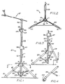
- Figure 1 is an elevation view of a preferred adjustable tripod stand in accordance with one embodiment of the present invention.
- Figure 2 is a transverse cross-section through the lower portion of the adjustable tripod stand taken along line 2-2 of Figure 1.
- Figure 3 is a partial elevation view of the stand of Figure 1 shown with the legs adjusted for placement on a multi-level surface.
- Figure 4 is a partial elevation view of an embodiment of a leg member having casters at the bottom end.
- Figure 5 is an elevational view of the stand having its legs adjusted to position the centre of gravity of the supported article within the support base.
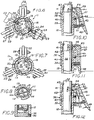
- Figure 6 is a transverse cross-section through the leg support upper collar member of the stand of Figure 1.
- Figure 7 is a transverse cross-section through the leg brace support lower collar member of the stand of Figure 1.
- Figure 8 is a transverse cross-section through the inner and outer tubular members of the stand of Figure 1.
- Figure 9 is a longitudinal cross-section through the bottom portion of the inner and outer tubular members of the stand of Figure 1.
- Figures 10 - 12 are longitudinal cross-sections illustrating the latch clutch mechanism of the stand of Figure 1.
- a preferred adjustable tripod stand 10 having a longitudinal upright portion 11 formed of telescoping tubular members.
- the lower section of the upright portion 11 comprises an elongate outer tubular member 12 having a plurality of circumferentially spaced grooves extending longitudinally on its exterior surface.
- four grooves are shown, two diametrically opposed grooves 13 being generally U-shaped in cross-section, and the other two diametrically opposed grooves 14 being dovetail shaped in cross-section.
- a pair of semi-circular upper leg support collar members 15 and 16 and a pair of semi-circular leg brace support collar members 17 and 18 are slidably mounted on the outer tubular member 12.
- Each of the collar members 15, 16, 17, and 18 are semi-circular in cross-section with the longitudinal edges 19 bent inwardly to be received within the longitudinal grooves 13.
- a semi-circular sleeve element 20 is installed between the exterior of the outer tubular member 12 and the interior of each collar segment.
- the sleeve element 20 is of a low friction material, such as nylon, to facilitate sliding movement of the collar segments on the outer tubular member.
- a pair of wedge elements 21 are slidably received within the dovetail grooves 14 inwardly adjacent to each of the collar segments. Each wedge 21 is slightly smaller in cross-section than the dovetail groove 14.
- a hole 22 extends radially through the side wall of each collar segment and each sleeve and each wedge 21 has a threaded stud 25.
- Wing nuts 23 are provided which have a shank portion 24 internally threaded to fit stud 25.
- each collar 15 and 16 are independently movable relative to one another and the outer tubular member.
- the wing screw 23 is tightened, its shoulder 26 engages the exterior of the collar and the wedge 21 is drawn into firm engagement on the angular sides of the dovetail groove 14, thus locking the collars 15 and 16 in a desired position on the outer tubular member 12.
- the leg brace support collar members 17 and 18 are substantially similar in construction and operation to the upper leg support collar members 15 and 16 (Figure 7).
- Each collar segment 17 and 18 is semi-circular in cross-section with the longitudinal edges 19 bent inwardly to be received within the longitudinal grooves 13, each has a semi-circular sleeve element 20 installed between the exterior of the outer tubular member 12 and the interior of each collar segment bore, and are connected by wing screws 23 to slidably move independently on the outer tubular member 12 as described above.
- each collar 15, 16, 17, and 18 is independently movable relative to one another and the outer tubular member, and each may be locked in a desired position on the outer tubular member 12.
- the upper leg support collar members 15 and 16 have integral tongues 27 projecting radially from their exterior and the leg brace support collar members 17 and 18 have integral yokes 28 projecting radially from their exterior.
- the yokes and tongues are equally spaced apart circumferentially for mounting three legs thereon. Although three tongues and three yokes are illustrated, it should be understood, that more than three may- be provided for mounting more than three legs.
- leg member 29 The upper end of a leg member 29 is pivotally mounted on each tongue 27 and a leg brace member 30 is pivotally mounted at one end in each yoke 28. The free end of the leg brace 30 is pivotally connected to the leg member 29 intermediate its ends.
- a foot pad 31 formed of resilient material is provided on the bottom end of each leg member. It should be understood that the bottom end of each leg member 29 may also be provided with a wheel or caster 31A as seen in Figure 4.
- the upper leg support collars 15 and 16 and the leg brace collars 17 and 18 may be positioned in vertically spaced pairs relative to the other vertically spaced pair.
- one of the upper leg collar segments 15 or 16 and its corresponding leg brace collar segment 17 or 18 may both be moved upward on the tubular member 12 relative to the other pair and the bottom of the leg(s) connected to the upper pair will be raised d relative to the other leg(s).
- the legs may also be extended radially inward and outward. This allows for placement of the stand on an uneven or multi-level surface or platform and also in limited or confined areas.
- the legs may be adjusted relative to an uneven or multi-level surface to cause the vertical axis of the stand to be disposed in an off-vertical axis position for placing the centre of gravity of the supported article relative to the centre of the supporting legs even if they are at different heights.
- an elongate inner tubular member 32 is slidably received within the outer tubular member 12.
- the outer tubular member 12 may have a pair of diametrically opposed U-shaped grooves 33 extending longitudinally on its interior surface and the lower end of the inner tubular member 32 may be provided with a rod or pin 34 extending transversely through its side wall. The outer ends of the rod or pin 34 are received within the opposed grooves 33 to prevent relative rotary movement between the inner and outer tubular members but allowing relative longitudinal movement.
- the bottom end of the outer tubular member 12 may be enclosed by an end cap 35 secured therein by a set screw 36 or other conventional means.
- This causes air to be trapped within the tubular members and to escape slowly through the clearance annulus between the tubular members if the inner tubular member is suddenly released.
- the air within the upright portion of the stand acts as a shock absorber and allows the inner tubular member to descend slowly in the event that it is suddenly or accidentally released.
- the top end of the inner tubular member, or a subsequent upper tubular member is provided with an end fitting which substantially closes off the top end of the upright members.
- the open bottom end of the inner tubular member 32 may have a plug 37 whereby it would act as a loosely fitting piston within the outer tubular member 12.
- a clamp member 38 is mounted on the top end of the outer tubular member 12.
- Clamp member 38 has a generally cylindrical body 39 with a bore 40 extending from the bottom end and terminating in a reduced diameter intermediate bore 41 forming a circumferential shoulder 42 therebetween and the intermediate bore 41 terminates in a smaller bore 43 at the top end of the clamp body.
- the bore 40 is slightly larger than the outside diameter of the outer tubular member 12 to be slidably received thereon, and the smaller bore 43 is slightly larger than the outside diameter of the inner tubular member 32 allowing it to pass slidably therethrough.
- the shoulder 42 engages the top end of the outer tubular member 12 and the intermediate bore 41 is larger than the outside diameter of the inner tubular member 32 defining an annulus therebetween.
- the clamp member 38 is secured to the top of the outer tubular member 12 by a set screw 44 or other conventional means.
- a longitudinal slot 45 extends along one side of the clamp body 39 and an opening 46 extends laterally between the intermediate bore 41 and the slot 45.
- a lever member 47 having a hand grip portion 48 with an inwardly facing camming surface 49 at the upper end thereof is pivotally supported on a pin 50 within the slot 45.
- a compression spring 51 has one end engaged in the clamp body 39 and its other end engaged on the hand grip portion 48 of the lever 47.
- the inner face of the camming surface 49 is divided into three angular planes A, B, and C.
- Figure 10 shows the clamp member 38 with its lever 47 in an intermediate position wherein the middle angular plane B of the camming surface 49 is engaged on the exterior of the inner tubular member 32.
- the spring 51 provides sufficient force to frictionally engage the middle angular plane B with the inner tubular member 32 whereby the inner tubular member is maintained at the selected height under normal support conditions but may be rotated without gripping the lever, upon application of sufficient force to overcome the frictional engagement.
- the clamp member 38 acts as a friction clutch.
- Figure 11 shows the clamp member 38 with lever 47 in an unlocked position wherein the hand grip portion 48 is squeezed inward to align the lower angular plane C of the camming surface 49 substantially parallel to the exterior of the inner tubular member 32.
- the inner tubular member 32 slides freely through the clamp member as long as the lever 47 is pressed inward.
- the spring 51 returns the lever to the intermediate position to frictionally engage the middle angular plane B with the inner tubular member as described above.
- Figure 12 shows the clamp member 38 with its lever 47 in an upper or locked position wherein the hand grip portion 48 is pivotally raised past the intermediate position to forcefully engage the upper plane A of camming surface 49 with the exterior of inner tubular member 32.
- the upper angular plane A of camming surface 49 is wedged against the exterior of the inner tubular member 32.
- the inner tubular member 32 is securely locked at the selected height under heavy support conditions to prevent accidental or unexpected longitudinal movement.
- a third tubular member 52 may be slidably received inside the inner tubular member 32 and a conventional split clamp member 53 having the usual bolt and wing nut 54 to may be secured at the upper end of the inner tubular member 32 to clamp the third tubular member 52 at a desired height.
- a conventional inverted L-shaped clamp member 55 having the usual bolt and wing nut 56 may also be installed on the exterior of third tubular member 52 and engaged on the clamp 53 to maintain the upper portion of the upper upstanding members at the desired circumferential orientation relative to the base portion.
- the top portion of the stand may be provided with various conventional tripod mounting hardwarc for mounting a variety of articles and instruments such things as camera, video equipment, telescopes, surveying instruments, and musical instruments. It should be understood that the particular tripod stand illustrated has a top portion configured to support musical cymbals, however other top portions may be provided for supporting such things as cameras, video equipment, telescopes, surveying instruments and the like.
Landscapes
- Engineering & Computer Science (AREA)
- General Engineering & Computer Science (AREA)
- Mechanical Engineering (AREA)
- Accessories Of Cameras (AREA)
- Auxiliary Devices For Music (AREA)
Applications Claiming Priority (2)
| Application Number | Priority Date | Filing Date | Title |
|---|---|---|---|
| US535580 | 1974-12-23 | ||
| US07/535,580 US5072910A (en) | 1990-06-11 | 1990-06-11 | Adjustable tripod stand |
Publications (2)
| Publication Number | Publication Date |
|---|---|
| EP0461838A1 EP0461838A1 (en) | 1991-12-18 |
| EP0461838B1 true EP0461838B1 (en) | 1999-05-26 |
Family
ID=24134848
Family Applications (1)
| Application Number | Title | Priority Date | Filing Date |
|---|---|---|---|
| EP91305215A Expired - Lifetime EP0461838B1 (en) | 1990-06-11 | 1991-06-10 | Adjustable tripod stand |
Country Status (6)
| Country | Link |
|---|---|
| US (1) | US5072910A (enExample) |
| EP (1) | EP0461838B1 (enExample) |
| JP (1) | JPH0658489A (enExample) |
| CA (1) | CA2042715C (enExample) |
| DE (1) | DE69131265T2 (enExample) |
| TW (1) | TW259839B (enExample) |
Families Citing this family (58)
| Publication number | Priority date | Publication date | Assignee | Title |
|---|---|---|---|---|
| US5374017A (en) * | 1989-02-17 | 1994-12-20 | Martin; William B. | Cable fitting |
| USD335889S (en) | 1990-08-24 | 1993-05-25 | Kahlil Gibran | Tripod |
| DE9201094U1 (de) * | 1992-01-30 | 1992-03-19 | Johs. Link GmbH & Co KG, 5920 Bad Berleburg | Stativ zum Halten von Gegenständen |
| US5794899A (en) * | 1996-07-19 | 1998-08-18 | Tamllos; George Michael | Hunting tripod |
| US5992805A (en) * | 1996-10-03 | 1999-11-30 | Tanner; Jeff | Media master apparatus |
| US5863015A (en) * | 1997-08-14 | 1999-01-26 | Hsu; Hsin-Hsuan | Microphone stand elevating device |
| DE59909174D1 (de) * | 1999-01-22 | 2004-05-19 | Leica Geosystems Ag | Verriegelbares Stativ |
| US6491266B1 (en) * | 2002-02-13 | 2002-12-10 | Yoga Electronics Co., Ltd. | Foldable stand with rotatable legs for camera or microphone |
| US7048241B2 (en) | 2002-04-19 | 2006-05-23 | Crain Enterprises, Inc. | Geomatic support having hinged legs with hinge lock |
| US7124985B2 (en) | 2002-04-19 | 2006-10-24 | Crain Enterprises, Inc. | Geomatic pole support with telescoping legs and locks |
| US7207534B2 (en) | 2002-04-19 | 2007-04-24 | Crain Enterprises, Inc. | Geomatic pole support and foot therefor |
| US7222827B2 (en) | 2002-04-19 | 2007-05-29 | Crain Enterprises, Inc. | Telescoping leg lock with thumb actuator |
| US7631842B2 (en) * | 2002-04-19 | 2009-12-15 | Seco Manufacturing Company, Inc. | Modular geomatic pole support system |
| US7588228B2 (en) * | 2003-01-16 | 2009-09-15 | May Randall L | Adjustable tripod stand |
| US7703725B2 (en) * | 2003-01-16 | 2010-04-27 | Randall L May | Adjustable tripod stand |
| US20070102598A1 (en) * | 2005-03-11 | 2007-05-10 | Nichols Dennis C | Vehicle hub support |
| JP4495042B2 (ja) * | 2005-07-14 | 2010-06-30 | 星野楽器株式会社 | スタンド |
| SE529407C2 (sv) * | 2005-12-08 | 2007-08-07 | Expand Int Ab | Ett displayorgan |
| US7718878B2 (en) * | 2006-06-09 | 2010-05-18 | Randall L May | Musical instrument stand with assisted extension |
| US7438266B2 (en) * | 2006-06-09 | 2008-10-21 | Randall L May | Stackable instrument stadium hardware stand |
| WO2008024779A2 (en) * | 2006-08-21 | 2008-02-28 | Baldwin Katherine L | Wind instrument with compliant actuator structures |
| JP2008185174A (ja) * | 2007-01-31 | 2008-08-14 | Yamaha Miyuujitsuku Trading Kk | 補助装置 |
| US7802764B2 (en) * | 2007-05-14 | 2010-09-28 | Leinen Chris M | Adjustable wheeled IV stand |
| US20080283698A1 (en) * | 2007-05-14 | 2008-11-20 | Lorenz Michael L | Instrument stand |
| US8093479B2 (en) * | 2009-08-06 | 2012-01-10 | Schafer Mark W | Percussion instrument carrier system |
| US8026433B2 (en) * | 2010-01-07 | 2011-09-27 | Ned Allen Place | Apparatus for using a person's hips to carry the load of marching percussion equipment or other objects which are carried near waist-height and in front of a person |
| US9863573B2 (en) | 2010-02-18 | 2018-01-09 | Randall May International Incorporated | Instrument and speaker lift stand |
| US8633365B2 (en) | 2010-12-14 | 2014-01-21 | Randall Lee May | Instrument and speaker lift stand |
| US20110255929A1 (en) * | 2010-04-15 | 2011-10-20 | Buchner David J | Universal Drill Stand |
| US9377158B2 (en) * | 2010-12-14 | 2016-06-28 | Randall May International, Inc. | Articulating amplifier stand |
| JPWO2013012027A1 (ja) * | 2011-07-20 | 2015-02-23 | 鈴木 昌彦 | 支持脚機構 |
| JP5485235B2 (ja) * | 2011-08-17 | 2014-05-07 | 星野楽器株式会社 | 楽器用スタンド |
| US8802951B2 (en) | 2012-04-30 | 2014-08-12 | Dale A Hallerberg | Gravitating musical instrument support |
| CN103453485B (zh) * | 2012-05-31 | 2018-11-06 | 海洋王照明科技股份有限公司 | 一种灯具及其三脚架装置 |
| US10208889B2 (en) * | 2017-05-29 | 2019-02-19 | Tcg Partners, Llc—Intellectual Property Series | Collapsible three legged platform |
| JP6719889B2 (ja) * | 2015-11-13 | 2020-07-08 | 関電プラント株式会社 | 三脚 |
| US10092125B1 (en) * | 2016-02-16 | 2018-10-09 | Benjamin A. Braunberger | Stand that holds an item or object in an upright manner |
| CN105909937A (zh) * | 2016-06-21 | 2016-08-31 | 石为 | 一种伸缩式稳定性摄影支架装置 |
| US10149529B1 (en) * | 2016-06-27 | 2018-12-11 | LaToya Turner | Ultimate hair stand system and method |
| JP6714916B2 (ja) * | 2017-12-07 | 2020-07-01 | 星野楽器株式会社 | スタンド及びハイハットスタンド |
| JP6484326B1 (ja) * | 2017-12-28 | 2019-03-13 | ベルボン株式会社 | 支持装置 |
| US10704731B2 (en) * | 2018-01-29 | 2020-07-07 | Sun Kyoung Kim | Sixpod for camera, speaker and the like |
| US11028965B2 (en) * | 2018-02-12 | 2021-06-08 | Savage Universal Corporation | Portable stable tripod for photographic equipment |
| USD897091S1 (en) * | 2018-03-08 | 2020-09-29 | Craig Edward Nelson | Walking aid |
| US11221544B1 (en) * | 2018-09-10 | 2022-01-11 | Brian York | Portable camera support device for elevated photography and/or videography |
| EP3671003A1 (en) * | 2018-12-20 | 2020-06-24 | Savage Universal Corporation | A support stand for photography |
| US11076712B2 (en) * | 2019-07-31 | 2021-08-03 | Timothy D Wobig | Portable equipment support stand |
| US11480290B2 (en) * | 2019-12-20 | 2022-10-25 | Really Right Stuff, Llc | Travel tripod |
| USD930971S1 (en) * | 2020-06-15 | 2021-09-21 | Craig Edward Nelson | Walking aid attachment |
| US11047523B1 (en) * | 2020-08-26 | 2021-06-29 | Kupo Co., Ltd. | Tripod |
| US11371648B1 (en) * | 2021-04-19 | 2022-06-28 | Tsun-Chi Liao | Positioning structure for tripod stand for quickly releasing clamping state |
| CN113217782B (zh) * | 2021-04-30 | 2022-08-19 | 中国一冶集团有限公司 | 一种建筑施工用延展式测量仪器支架 |
| US20220349678A1 (en) * | 2021-05-03 | 2022-11-03 | Apex Ip Holdings, Llc | Auto-illuminating dry fire target |
| USD969902S1 (en) * | 2021-06-11 | 2022-11-15 | Shenzhen wei bo technology co., LTD | Folding tripod |
| US11441589B1 (en) | 2021-06-30 | 2022-09-13 | Brent Ravnaas | Locking device for a telescoping leg |
| CN114658965B (zh) * | 2022-02-24 | 2024-08-20 | 南昌大学 | 一种用于城乡规划的工程测量设备 |
| US11606946B1 (en) | 2022-04-05 | 2023-03-21 | Active Outdoors Llc | Fishing rod stand assembly |
| US20250043907A1 (en) * | 2023-08-01 | 2025-02-06 | Motomotion China Corporation | Mounting assembly for mounting a tv onto a bed frame |
Family Cites Families (15)
| Publication number | Priority date | Publication date | Assignee | Title |
|---|---|---|---|---|
| US740886A (en) * | 1902-02-01 | 1903-10-06 | Albert S Marten | Stand or support for horns. |
| US773787A (en) * | 1903-11-09 | 1904-11-01 | Abner Crossman | Supporting device for clothes-horses, &c. |
| US1517825A (en) * | 1923-06-21 | 1924-12-02 | Bruneau Eugene | Tripod |
| US1795747A (en) * | 1928-10-22 | 1931-03-10 | Underwood & Underwood Inc | Tripod |
| US1894695A (en) * | 1930-08-15 | 1933-01-17 | Ley George Albert | Tripod |
| US2642247A (en) * | 1950-02-04 | 1953-06-16 | Norwood Company | Collapsible stand |
| US2864577A (en) * | 1954-08-31 | 1958-12-16 | Da Lite Screen Company Inc | Foldable standard base structure |
| AT224831B (de) * | 1960-12-01 | 1962-12-10 | Heinrich Dipl Ing Wuester | Vorrichtung zum gegenseitigen Festklemmen von ineinanderschiebbaren Rohren |
| US3312432A (en) * | 1965-05-20 | 1967-04-04 | Redeman Corp | Mobile stand |
| US3307814A (en) * | 1966-05-09 | 1967-03-07 | Jr Earl M Bogar | Adjustable stand for instruments |
| US3570130A (en) * | 1968-12-04 | 1971-03-16 | Sheldon Boehm | Holding device for surveying instruments |
| US3589757A (en) * | 1969-06-03 | 1971-06-29 | Quick Set Inc | Automatic lock for extensible camera tripod leg |
| JPS4948132B1 (enExample) * | 1970-12-30 | 1974-12-19 | ||
| US4215839A (en) * | 1978-10-10 | 1980-08-05 | Kahlil Gibran | Tripod |
| US4988064A (en) * | 1988-05-16 | 1991-01-29 | Hoshino Gakki Co., Ltd. | Tiltable tripod stand |
-
1990
- 1990-06-11 US US07/535,580 patent/US5072910A/en not_active Expired - Fee Related
-
1991
- 1991-05-16 CA CA002042715A patent/CA2042715C/en not_active Expired - Fee Related
- 1991-06-10 DE DE69131265T patent/DE69131265T2/de not_active Expired - Fee Related
- 1991-06-10 EP EP91305215A patent/EP0461838B1/en not_active Expired - Lifetime
- 1991-06-10 JP JP3138071A patent/JPH0658489A/ja active Pending
- 1991-06-24 TW TW080104889A patent/TW259839B/zh active
Also Published As
| Publication number | Publication date |
|---|---|
| US5072910A (en) | 1991-12-17 |
| CA2042715C (en) | 2001-01-23 |
| DE69131265T2 (de) | 2001-02-15 |
| DE69131265D1 (de) | 1999-07-01 |
| JPH0658489A (ja) | 1994-03-01 |
| EP0461838A1 (en) | 1991-12-18 |
| CA2042715A1 (en) | 1991-12-12 |
| TW259839B (enExample) | 1995-10-11 |
Similar Documents
| Publication | Publication Date | Title |
|---|---|---|
| EP0461838B1 (en) | Adjustable tripod stand | |
| US7703725B2 (en) | Adjustable tripod stand | |
| US4671479A (en) | Adjustable support apparatus | |
| US6554235B1 (en) | Support post with adjustable accessory supports | |
| US5934628A (en) | Portable vertical support | |
| US7604207B2 (en) | Tripod and method | |
| US4317552A (en) | Universal tripod for supporting a camera or the like | |
| US8398037B2 (en) | Equipment support | |
| US20050274854A1 (en) | Adjustable tripod stand | |
| US5222705A (en) | Tripod having collapsible leg assemblies and extendible neck and latch mechanisms for maintaining leg assemblies and neck in predetermined positions | |
| US6412737B1 (en) | Support stand | |
| US20120138763A1 (en) | Versatile camera support mount | |
| US8100371B2 (en) | I.V. support stand and clamp apparatus | |
| US5505415A (en) | Tripod | |
| EP0533376A1 (en) | Portable stands or supports | |
| US12345372B2 (en) | Travel tripod | |
| JPH01501243A (ja) | カメラおよび他の機器支持スタンド | |
| WO2003063367A2 (en) | Adjustable support apparatus | |
| US7438266B2 (en) | Stackable instrument stadium hardware stand | |
| US11042077B2 (en) | Gimbal supporting frame | |
| JP3464565B2 (ja) | 支持スタンド | |
| JP2005518309A (ja) | 姿勢応答解放付き係止入れ子部材 | |
| US3022974A (en) | Accessory holding device | |
| AU757766B2 (en) | Camera leveling head | |
| US20200261784A1 (en) | Pinata holding device |
Legal Events
| Date | Code | Title | Description |
|---|---|---|---|
| PUAI | Public reference made under article 153(3) epc to a published international application that has entered the european phase |
Free format text: ORIGINAL CODE: 0009012 |
|
| AK | Designated contracting states |
Kind code of ref document: A1 Designated state(s): DE FR GB IT |
|
| 17P | Request for examination filed |
Effective date: 19920611 |
|
| 17Q | First examination report despatched |
Effective date: 19930524 |
|
| APAB | Appeal dossier modified |
Free format text: ORIGINAL CODE: EPIDOS NOAPE |
|
| APAA | Appeal reference recorded |
Free format text: ORIGINAL CODE: EPIDOS REFN |
|
| APCB | Communication from the board of appeal sent |
Free format text: ORIGINAL CODE: EPIDOS OBAPE |
|
| APCB | Communication from the board of appeal sent |
Free format text: ORIGINAL CODE: EPIDOS OBAPE |
|
| APAB | Appeal dossier modified |
Free format text: ORIGINAL CODE: EPIDOS NOAPE |
|
| GRAG | Despatch of communication of intention to grant |
Free format text: ORIGINAL CODE: EPIDOS AGRA |
|
| GRAG | Despatch of communication of intention to grant |
Free format text: ORIGINAL CODE: EPIDOS AGRA |
|
| GRAH | Despatch of communication of intention to grant a patent |
Free format text: ORIGINAL CODE: EPIDOS IGRA |
|
| GRAH | Despatch of communication of intention to grant a patent |
Free format text: ORIGINAL CODE: EPIDOS IGRA |
|
| GRAA | (expected) grant |
Free format text: ORIGINAL CODE: 0009210 |
|
| AK | Designated contracting states |
Kind code of ref document: B1 Designated state(s): DE FR GB IT |
|
| PG25 | Lapsed in a contracting state [announced via postgrant information from national office to epo] |
Ref country code: IT Free format text: LAPSE BECAUSE OF FAILURE TO SUBMIT A TRANSLATION OF THE DESCRIPTION OR TO PAY THE FEE WITHIN THE PRE;WARNING: LAPSES OF ITALIAN PATENTS WITH EFFECTIVE DATE BEFORE 2007 MAY HAVE OCCURRED AT ANY TIME BEFORE 2007. THE CORRECT EFFECTIVE DATE MAY BE DIFFERENT FROM THE ONE RECORDED.SCRIBED TIME-LIMIT Effective date: 19990526 |
|
| REF | Corresponds to: |
Ref document number: 69131265 Country of ref document: DE Date of ref document: 19990701 |
|
| ET | Fr: translation filed | ||
| PLBE | No opposition filed within time limit |
Free format text: ORIGINAL CODE: 0009261 |
|
| STAA | Information on the status of an ep patent application or granted ep patent |
Free format text: STATUS: NO OPPOSITION FILED WITHIN TIME LIMIT |
|
| 26N | No opposition filed | ||
| REG | Reference to a national code |
Ref country code: GB Ref legal event code: IF02 |
|
| REG | Reference to a national code |
Ref country code: FR Ref legal event code: ST |
|
| REG | Reference to a national code |
Ref country code: FR Ref legal event code: RN |
|
| REG | Reference to a national code |
Ref country code: FR Ref legal event code: D3 |
|
| PGFP | Annual fee paid to national office [announced via postgrant information from national office to epo] |
Ref country code: GB Payment date: 20040610 Year of fee payment: 14 |
|
| PGFP | Annual fee paid to national office [announced via postgrant information from national office to epo] |
Ref country code: FR Payment date: 20040630 Year of fee payment: 14 |
|
| PGFP | Annual fee paid to national office [announced via postgrant information from national office to epo] |
Ref country code: DE Payment date: 20040831 Year of fee payment: 14 |
|
| PG25 | Lapsed in a contracting state [announced via postgrant information from national office to epo] |
Ref country code: GB Free format text: LAPSE BECAUSE OF NON-PAYMENT OF DUE FEES Effective date: 20050610 |
|
| APAH | Appeal reference modified |
Free format text: ORIGINAL CODE: EPIDOSCREFNO |
|
| PG25 | Lapsed in a contracting state [announced via postgrant information from national office to epo] |
Ref country code: DE Free format text: LAPSE BECAUSE OF NON-PAYMENT OF DUE FEES Effective date: 20060103 |
|
| PG25 | Lapsed in a contracting state [announced via postgrant information from national office to epo] |
Ref country code: FR Free format text: LAPSE BECAUSE OF NON-PAYMENT OF DUE FEES Effective date: 20060228 |
|
| GBPC | Gb: european patent ceased through non-payment of renewal fee |
Effective date: 20050610 |
|
| REG | Reference to a national code |
Ref country code: FR Ref legal event code: ST Effective date: 20060228 |