EP0459867A1 - Gelenkverbindung zwischen einem Scheibenwischerarm und einem Scheibenwischerblatt - Google Patents
Gelenkverbindung zwischen einem Scheibenwischerarm und einem Scheibenwischerblatt Download PDFInfo
- Publication number
- EP0459867A1 EP0459867A1 EP91401308A EP91401308A EP0459867A1 EP 0459867 A1 EP0459867 A1 EP 0459867A1 EP 91401308 A EP91401308 A EP 91401308A EP 91401308 A EP91401308 A EP 91401308A EP 0459867 A1 EP0459867 A1 EP 0459867A1
- Authority
- EP
- European Patent Office
- Prior art keywords
- arm
- opening
- brush
- sheath
- connection device
- Prior art date
- Legal status (The legal status is an assumption and is not a legal conclusion. Google has not performed a legal analysis and makes no representation as to the accuracy of the status listed.)
- Granted
Links
Images

Classifications
-
- B—PERFORMING OPERATIONS; TRANSPORTING
- B60—VEHICLES IN GENERAL
- B60S—SERVICING, CLEANING, REPAIRING, SUPPORTING, LIFTING, OR MANOEUVRING OF VEHICLES, NOT OTHERWISE PROVIDED FOR
- B60S1/00—Cleaning of vehicles
- B60S1/02—Cleaning windscreens, windows or optical devices
- B60S1/04—Wipers or the like, e.g. scrapers
- B60S1/32—Wipers or the like, e.g. scrapers characterised by constructional features of wiper blade arms or blades
- B60S1/40—Connections between blades and arms
- B60S1/4038—Connections between blades and arms for arms provided with a channel-shaped end
- B60S2001/4058—Connections between blades and arms for arms provided with a channel-shaped end comprising a separate locking element, e.g. in addition to an intermediate element
Definitions
- the present invention relates to a hinge connection device between a wiper blade and a wiper arm, in particular for motor vehicles.
- a sheath in an opening carried by the back of the main stirrup of the brush, generally rectangular opening with flanks substantially parallel in pairs.
- a hinge pin is carried either by the brush or by the sheath, and there is attached, around said axis, a connecting element, said connector, making it possible to connect this axis with the end of a wiper arm - ice penetrating into this opening.
- wiper arm ends which mask the opening of the blade, by covering it, while ensuring the proper connection. articulated with the broom.
- the object of the present invention is to have a hinge connection device between one end of an arm covering a brush which is of a very simple design and very easy to handle, during assembly / disassembly.
- the articulation connection device between a wiper arm and a wiper blade has an opening capable of receiving a sheath and said arm having in section an inverted "U" shape at least. in the region of the opening of said broom and suitable for covering said opening by being connected to articulation with said brush by a hinge pin
- the sheath carries stop means in translation and / or in rotation of the arm relative to the brush.
- the arm is connected to the broom in a very simple manner while being guided perfectly with respect thereto.
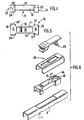
- This wiper blade usually comprises a frame carrying a wiper blade consisting of a main stirrup 2 at the ends of which is articulated at least one intermediate stirrup carrying the wiper blade.
- This main stirrup has, in section, an inverted "U" shape with two sides 3,4 substantially parallel to one another and connected by a back 5.
- an opening 6, of generally rectangular shape, is provided, the long sides 7 of which coincide with the intersection of the sides 3.4 and of the back 5 and the short sides 8 of which delimit in the longitudinal direction of this opening.
- the opening 6 is able to receive a sheath 9, also of generally rectangular shape and corresponding to the longitudinal and transverse dimensions of this opening.
- the sheath 9 has a hollowed-out body 10 of generally rectangular shape having two longitudinal walls 11,12 substantially parallel to one another and delimited at their ends by two transverse walls 13,14, these walls delimiting a recess 15.
- a hinge pin 16 arranged parallel to the transverse walls 13, and which can be in one piece with the body 10.
- the hinge pin can be carried by the main stirrup 2 and this at its opening 6 and, in this case, the hollow body 10 will have two ribs opening out in the direction of this axis to allow the introduction of the sleeve 9 into this opening.
- the hollow body continues with a front apron 17, seen on the left from FIG. 1, this apron consisting of a flat wall 18 coming from the upper edge of the transverse wall 14 and by a rear apron 19, considered on the right from of Figure 1, and also consisting of a flat wall 20 from the transverse wall 13 of the hollow body 10, these decks being stiffened relative to their transverse walls respective by stiffening ribs 21,22 arranged orthogonally, on the one hand, with respect to the transverse walls 13,14 and, on the other hand, with respect to the plane walls 18,20.
- the front apron 17 carries front legs 23 disposed substantially parallel to the longitudinal walls 11, 12 while being arranged at a distance therefrom, and the rear apron carries rear legs 24 arranged identically to the front legs 23.
- the tabs 23, 24 bear, at their free end, opposite to that where they are anchored to the respective aprons, hooking projections 25.
- the dimensions of the sheath thus formed are such that the longitudinal dimension, considered between the two end parts of the aprons 17,19, corresponds to the length of the opening 6, the dimension considered between the two external faces of the longitudinal walls 11,12 corresponds to the internal dimension considered between the two internal faces of the walls 3, 4 of the main stirrup 2, the dimension between the two front and rear legs considered between the internal faces of these legs corresponds to the dimension considered between the external faces of the sides 3,4 of said main caliper 2.
- the sides 3,4 prefferably, provision is made for the sides 3,4 to have at their free end recesses 3 ′, 4 ′ serving as means for locking the sheath 9 and suitable to cooperate with the attachment projections 25 provided at the free ends of the front and rear legs 23,24.
- the front legs 23 carry, on their external faces, a protuberance 26 having, opposite their part corresponding to the extension of the free end of the planar wall 18, a portion of circular wall 26 ′ serving as a front stop and whose the role will be explained later.
- the rear legs 24 also carry, opposite their end corresponding to the extension of the free end of the wall 20, a cylindrical surface 27 provided in the thickness of said legs and serving as a rear stop.
- the end of the wiper arm 28 has, at its connection with the blade 1, a section in the form of an inverted "U" with substantially parallel sides 29, 30 and connected by a back 31.
- At least one of the sides 29.30 has a projection 32 directed towards the inside of the "U" and, here, of circular shape.
- an opening 33 adapted to receive a latch 34, this opening having a first substantially rectangular part 35 extending by a second part 36 also substantially rectangular but of larger transverse dimension.
- the free end 37 of the end of the arm 28 has on the flanks 29, 30 circular parts 38 of complementary shape to the cylindrical surfaces 26 ′ carried by the front legs 23.
- the lock 34 has a hooking portion 39 of dimensions slightly smaller than the first rectangular portion 35 of the opening 33 and consisting of two branches 40, 41 which are elastic with respect to one another, delimiting an open cylindrical housing 42 at both ends and having, from one of its edges longitudinal, a triangular shaped slot 43 serving as a mounting ramp.
- the latch 34 has a flat surface 44 provided with a gripping projection 45 arranged in the vicinity of the attachment portion 39.
- the various elements are assembled first by fitting the sleeve 9 into the opening 6 of the main stirrup, so that the tabs 23, 24 are located on the external faces of the sides 3.4 of the stirrup, the hooking projections 25 snap into the recesses 3 ′, 4 ′.
- the lock 34 is attached to the arm and more precisely the attachment portion 39 enters the rectangular portion 36 provided on the back 31 of the end 28.
- the end 28 of the arm is then attached to the assembly consisting of the sheath 9 and the stirrup 2 so that, on the one hand, the internal wall of the back 31 is supported on this sheath 9 and, on the other hand, the circular parts 38 of the arm 28 come to bear on the cylindrical surfaces 26 ′ of the sheath 9, while the projection 32 of the arm 28 slides on the cylindrical surface 27 of the sheath 9 defined previously.
- the internal walls of the sides 29.30 of the end of the arm 28 slide respectively on the external faces of the legs 23.24, more precisely the internal walls located in the vicinity of the end 37 slide on the face outer of the legs 23 included between the cylindrical surfaces 26 ′ and the lateral edge of said legs.
- the latch 34 slides so that the branches 40, 41 of said latch are elastically erased so as to be able to slide around the articulation axis 16 carried, either by l main caliper, either by the sheath 9, so as to link the arm carrying the latch with the hinge pin 16.
- cylindrical surfaces 26 ′ carried by the lugs 23 serve as a translation stop for the end of the arm with respect to the brush and, likewise, the cylindrical surfaces 27 associated with the projection 32 serve to translation stop in another direction for the arm with respect to this brush.
- the internal faces of the sides 29, 30 of the arm slide on the external faces of the tabs 23, 24 and no longer provide a metal to metal contact but a metal to plastic contact, which improves the quality of the joint by generating no noise and less wear.
- the brush can pivot around the axis 16 thanks to the lock 34, the arm being trapped between this lock and the brush and the surfaces 26 ′, 27 associated with the circular parts 38 and the projection 32 form a stop in translation in both directions for the arm 28 relative to the brush 1 while allowing the movement of the brush by sliding of the circular parts 38 and of the projection 32 on the surfaces 26 ′, 27.
- the disassembly is ensured by a translational movement of the lock 34 in a movement from left to right allowing the release of the axis 16 out of the housing 42 and, in this way, the arm 28 is no longer linked to the brush 1.
- FIG. 6 shows an alternative embodiment of the invention in which means for limiting the movement of the arm relative to the brush are provided.
- an opening 46 consisting of a first rectangular part 47 continuing with a second rectangular part 48 and the bolt carries, from the face directed towards the sheath, a prominence 49 in the form of an inverted "T", the length of the horizontal bar of the T corresponds to the length of the second rectangular part of the opening 46 and the width of the vertical bar of the T corresponds to the width of the first rectangular part of the opening 46.
- the horizontal bar of the protrusion 49 penetrates into the first part of the opening 48 and, during the movement of translation of the lock allowing the attachment of the arm with the sheath and the brush, the vertical bar of the protuberance will slide along the longitudinal parts of the first rectangular part 47, the horizontal bar serving as a limit stop in movement of the arm relative to the brush.
Applications Claiming Priority (2)
| Application Number | Priority Date | Filing Date | Title |
|---|---|---|---|
| FR9006433 | 1990-05-23 | ||
| FR9006433A FR2662414B1 (fr) | 1990-05-23 | 1990-05-23 | Dispositif de liaison a articulation entre un bras d'essuie-glace et un balai d'essuie-glace. |
Publications (2)
| Publication Number | Publication Date |
|---|---|
| EP0459867A1 true EP0459867A1 (de) | 1991-12-04 |
| EP0459867B1 EP0459867B1 (de) | 1994-03-09 |
Family
ID=9396880
Family Applications (1)
| Application Number | Title | Priority Date | Filing Date |
|---|---|---|---|
| EP19910401308 Expired - Lifetime EP0459867B1 (de) | 1990-05-23 | 1991-05-21 | Gelenkverbindung zwischen einem Scheibenwischerarm und einem Scheibenwischerblatt |
Country Status (4)
| Country | Link |
|---|---|
| EP (1) | EP0459867B1 (de) |
| DE (1) | DE69101340T2 (de) |
| ES (1) | ES2051565T3 (de) |
| FR (1) | FR2662414B1 (de) |
Cited By (12)
| Publication number | Priority date | Publication date | Assignee | Title |
|---|---|---|---|---|
| FR2700309A1 (fr) * | 1993-01-11 | 1994-07-13 | Journee Paul Sa | Dispositif de liaison pour le raccordement et l'articulation d'un balai d'essuie-glace à l'extrémité d'un balai d'essuie-glace. |
| FR2738202A1 (fr) * | 1995-08-31 | 1997-03-07 | Valeo Systemes Dessuyage | Essuie-glace de vehicule automobile muni d'un capot d'habillage emboite sur un balai d'essuie-glace |
| FR2756239A1 (fr) * | 1996-11-27 | 1998-05-29 | Journee Paul Sa | Dispositif d'essuyage d'une vitre de vehicule automobile comportant des moyens perfectionnes d'accrochage d'un balai d'essuie-glace |
| WO1999033687A1 (de) * | 1997-12-24 | 1999-07-08 | Robert Bosch Gmbh | Wischvorrichtung für scheiben von kraftfahrzeugen mit einem am kraftfahrzeug geführten pendelnd angetriebenen wischerarm |
| FR2781191A1 (fr) * | 1998-07-20 | 2000-01-21 | Journee Paul Sa | Essuie-glace de vehicule automobile comportant un verrou pivotant |
| US6481044B1 (en) * | 1998-05-28 | 2002-11-19 | Paul Journee, S.A. | Motor vehicle wiper comprising a connector with a safety lock |
| FR2841516A1 (fr) * | 2002-06-28 | 2004-01-02 | Bosch Gmbh Robert | Raclette d'essuie-glace |
| JP2005297600A (ja) * | 2004-04-06 | 2005-10-27 | Honda Motor Co Ltd | ワイパーブレード連結構造 |
| CN1946599B (zh) * | 2004-04-22 | 2010-09-29 | 罗伯特·博世有限公司 | 刮水片 |
| US20120180247A1 (en) * | 2011-01-14 | 2012-07-19 | Dongguan Hongyi Wiper Co., Ltd. | Windshield wiper blade assembly |
| CN106004799A (zh) * | 2010-11-16 | 2016-10-12 | 戴姆勒股份公司 | 用于连接车辆刮水器装置的刮水片和刮水器臂的连接装置和方法 |
| WO2017119853A1 (en) * | 2016-01-06 | 2017-07-13 | Teklas Kaucuk Sanayi Ticaret A. S. | A connecting device for the vehicle wipers |
Families Citing this family (5)
| Publication number | Priority date | Publication date | Assignee | Title |
|---|---|---|---|---|
| DE102010052313A1 (de) * | 2010-11-16 | 2012-05-16 | Daimler Ag | Verbindungsanordnung und Verfahren zum Verbinden eines Wischblatts mit einem Wischarm für eine Scheibenwischanlage eines Fahrzeugs |
| DE102010052314A1 (de) * | 2010-11-16 | 2012-05-16 | Daimler Ag | Wischblattanordnung und Verbindungsanordnung mit einer Wischblattanordnung und einem Wischarm |
| DE102012011427A1 (de) | 2012-06-08 | 2012-12-27 | Daimler Ag | Wischarm und Verbindungsanordnung für eine Scheibenwischanlage eines Fahrzeugs |
| DE102012015983A1 (de) | 2012-08-10 | 2013-03-14 | Daimler Ag | Wischarm und Verbindungsanordnung für eine Scheibenwischanlage eines Fahrzeugs |
| DE102015011370A1 (de) | 2015-08-28 | 2017-03-02 | Daimler Ag | Wischblatt für eine Scheibenwischanlage eines Fahrzeugs und Verbindungsanordnung mit einem Wischblatt und einem Wischarm |
Citations (3)
| Publication number | Priority date | Publication date | Assignee | Title |
|---|---|---|---|---|
| FR2310243A1 (fr) * | 1975-05-09 | 1976-12-03 | Bosch Gmbh Robert | Dispositif d'essuyage de glaces de vehicules automobiles |
| DE8522252U1 (de) * | 1985-08-02 | 1986-11-27 | Robert Bosch Gmbh, 7000 Stuttgart, De | |
| EP0337042A1 (de) * | 1988-04-13 | 1989-10-18 | Paul Journee S.A. | Scheibenwischer für Kraftfahrzeug |
-
1990
- 1990-05-23 FR FR9006433A patent/FR2662414B1/fr not_active Expired - Lifetime
-
1991
- 1991-05-21 DE DE1991601340 patent/DE69101340T2/de not_active Expired - Fee Related
- 1991-05-21 ES ES91401308T patent/ES2051565T3/es not_active Expired - Lifetime
- 1991-05-21 EP EP19910401308 patent/EP0459867B1/de not_active Expired - Lifetime
Patent Citations (3)
| Publication number | Priority date | Publication date | Assignee | Title |
|---|---|---|---|---|
| FR2310243A1 (fr) * | 1975-05-09 | 1976-12-03 | Bosch Gmbh Robert | Dispositif d'essuyage de glaces de vehicules automobiles |
| DE8522252U1 (de) * | 1985-08-02 | 1986-11-27 | Robert Bosch Gmbh, 7000 Stuttgart, De | |
| EP0337042A1 (de) * | 1988-04-13 | 1989-10-18 | Paul Journee S.A. | Scheibenwischer für Kraftfahrzeug |
Cited By (19)
| Publication number | Priority date | Publication date | Assignee | Title |
|---|---|---|---|---|
| EP0606846A1 (de) * | 1993-01-11 | 1994-07-20 | Paul Journee S.A. | Verbindungs-und Gelenkeinrichtung zur Befestigung eines Scheibenwischblatts an einem Wischarm |
| FR2700309A1 (fr) * | 1993-01-11 | 1994-07-13 | Journee Paul Sa | Dispositif de liaison pour le raccordement et l'articulation d'un balai d'essuie-glace à l'extrémité d'un balai d'essuie-glace. |
| FR2738202A1 (fr) * | 1995-08-31 | 1997-03-07 | Valeo Systemes Dessuyage | Essuie-glace de vehicule automobile muni d'un capot d'habillage emboite sur un balai d'essuie-glace |
| FR2756239A1 (fr) * | 1996-11-27 | 1998-05-29 | Journee Paul Sa | Dispositif d'essuyage d'une vitre de vehicule automobile comportant des moyens perfectionnes d'accrochage d'un balai d'essuie-glace |
| WO1999033687A1 (de) * | 1997-12-24 | 1999-07-08 | Robert Bosch Gmbh | Wischvorrichtung für scheiben von kraftfahrzeugen mit einem am kraftfahrzeug geführten pendelnd angetriebenen wischerarm |
| US6687948B2 (en) * | 1997-12-24 | 2004-02-10 | Robert Bosch Gmbh | Wiping device for windows of motor vehicles having a wiper arm which is guided on the vehicle and driven in a pendulum manner |
| US6481044B1 (en) * | 1998-05-28 | 2002-11-19 | Paul Journee, S.A. | Motor vehicle wiper comprising a connector with a safety lock |
| US6609267B1 (en) | 1998-07-20 | 2003-08-26 | Paul Journee | Motor vehicle wiper comprising a pivoting lock |
| WO2000005113A1 (fr) * | 1998-07-20 | 2000-02-03 | Paul Journee S.A. | Essuie-glace de vehicule automobile comportant un verrou pivotant |
| FR2781191A1 (fr) * | 1998-07-20 | 2000-01-21 | Journee Paul Sa | Essuie-glace de vehicule automobile comportant un verrou pivotant |
| FR2841516A1 (fr) * | 2002-06-28 | 2004-01-02 | Bosch Gmbh Robert | Raclette d'essuie-glace |
| JP2005297600A (ja) * | 2004-04-06 | 2005-10-27 | Honda Motor Co Ltd | ワイパーブレード連結構造 |
| CN100393559C (zh) * | 2004-04-06 | 2008-06-11 | 本田技研工业株式会社 | 刮水器片连接构造 |
| CN1946599B (zh) * | 2004-04-22 | 2010-09-29 | 罗伯特·博世有限公司 | 刮水片 |
| CN106004799A (zh) * | 2010-11-16 | 2016-10-12 | 戴姆勒股份公司 | 用于连接车辆刮水器装置的刮水片和刮水器臂的连接装置和方法 |
| CN106004799B (zh) * | 2010-11-16 | 2019-03-01 | 戴姆勒股份公司 | 连接装置及元件、刮水器臂、刮水器臂组件和刮水器装置 |
| US20120180247A1 (en) * | 2011-01-14 | 2012-07-19 | Dongguan Hongyi Wiper Co., Ltd. | Windshield wiper blade assembly |
| US8381349B2 (en) * | 2011-01-14 | 2013-02-26 | Dongguan Hongyi Wiper Co., Ltd. | Windshield wiper blade assembly |
| WO2017119853A1 (en) * | 2016-01-06 | 2017-07-13 | Teklas Kaucuk Sanayi Ticaret A. S. | A connecting device for the vehicle wipers |
Also Published As
| Publication number | Publication date |
|---|---|
| DE69101340D1 (de) | 1994-04-14 |
| EP0459867B1 (de) | 1994-03-09 |
| ES2051565T3 (es) | 1994-06-16 |
| FR2662414B1 (fr) | 1992-07-31 |
| DE69101340T2 (de) | 1994-06-16 |
| FR2662414A1 (fr) | 1991-11-29 |
Similar Documents
| Publication | Publication Date | Title |
|---|---|---|
| EP0459867B1 (de) | Gelenkverbindung zwischen einem Scheibenwischerarm und einem Scheibenwischerblatt | |
| FR2781191A1 (fr) | Essuie-glace de vehicule automobile comportant un verrou pivotant | |
| FR2738201A1 (fr) | Essuie-glace pour vehicule automobile comportant un connecteur muni d'un capot articule perfectionne | |
| EP0448452A1 (de) | Verbindungsglied, um einen Scheibenwischerarm mit einem Scheibenwischerblatt zu verbinden | |
| FR2774050A1 (fr) | Essuie-glace de vehicule automobile | |
| FR2653080A1 (fr) | Dispositif connecteur pour balai d'essuie-glace, notamment pour vehicule automobile. | |
| FR2647733A1 (fr) | Cassette a miroir pour pare-soleil, notamment dans un habitacle d'automobile | |
| FR2767103A1 (fr) | Essuie-glace comportant des moyens perfectionnes d'articulation du balai d'essuie-glace sur le bras d'essuie-glace | |
| BE1017691A3 (fr) | Dispositif pour relier de maniere articulee un balai d'essuie-glace a un bras d'essuie-glace. | |
| EP0742329B1 (de) | Verriegelungsvorrichtung für Kraftwagenflügel mit verbesserten Einbaumitteln für Verkleidungskappe | |
| FR2781742A1 (fr) | Essuie-glace de vehicule automobile comportant des moyens perfectionnes de liaison et d'articulation du bras sur le balai de l'essuie-glace | |
| EP0555146B1 (de) | Scheibenwischer mit Abdeckkappe, insbesondere für Kraftfahrzeuge | |
| FR2731191A1 (fr) | Essuie-glace de vehicule automobile | |
| EP3902721A1 (de) | Adapter für ein wischerblatt eines kraftfahrzeugs | |
| EP0461987B1 (de) | Scheibenwischerblatt das mit einer Scheibenwischerleistensperre ausgestattet ist | |
| FR2594767A1 (fr) | Attache pour la fixation d'un balai d'essuie-glace a axe d'articulation sur un bras en forme de crochet | |
| EP0575242B1 (de) | Scheibenwischer mit Abdeckkappe, die am Befestigungsstift der Anpressfeder schwenkbar gelagert ist | |
| EP0251844B1 (de) | Klappgriff für eine Tür | |
| FR3135680A1 (fr) | Module de connexion d’un système d’essuyage. | |
| FR2653081A1 (fr) | Dispositif de connexion a articulation entre deux elements oscillants d'un balai d'essuie-glace. | |
| EP4124521A1 (de) | Verbindungsvorrichtung zwischen wischblatt und antriebsarm | |
| WO2023222840A1 (fr) | Dispositif de connexion d'un balai d'essuyage | |
| FR2912357A1 (fr) | Siege d'automobile comportant un carter de recouvrement d'un element d'armature articule. | |
| FR2786449A1 (fr) | Connecteur d'essuie-glace de vehicule automobile | |
| FR2756239A1 (fr) | Dispositif d'essuyage d'une vitre de vehicule automobile comportant des moyens perfectionnes d'accrochage d'un balai d'essuie-glace |
Legal Events
| Date | Code | Title | Description |
|---|---|---|---|
| PUAI | Public reference made under article 153(3) epc to a published international application that has entered the european phase |
Free format text: ORIGINAL CODE: 0009012 |
|
| AK | Designated contracting states |
Kind code of ref document: A1 Designated state(s): DE ES GB IT |
|
| 17P | Request for examination filed |
Effective date: 19920311 |
|
| 17Q | First examination report despatched |
Effective date: 19930705 |
|
| GRAA | (expected) grant |
Free format text: ORIGINAL CODE: 0009210 |
|
| AK | Designated contracting states |
Kind code of ref document: B1 Designated state(s): DE ES GB IT |
|
| GBT | Gb: translation of ep patent filed (gb section 77(6)(a)/1977) |
Effective date: 19940311 |
|
| REF | Corresponds to: |
Ref document number: 69101340 Country of ref document: DE Date of ref document: 19940414 |
|
| ITTA | It: last paid annual fee | ||
| ITF | It: translation for a ep patent filed |
Owner name: SOCIETA' ITALIANA BREVETTI S.P.A. |
|
| REG | Reference to a national code |
Ref country code: ES Ref legal event code: FG2A Ref document number: 2051565 Country of ref document: ES Kind code of ref document: T3 |
|
| PLBE | No opposition filed within time limit |
Free format text: ORIGINAL CODE: 0009261 |
|
| STAA | Information on the status of an ep patent application or granted ep patent |
Free format text: STATUS: NO OPPOSITION FILED WITHIN TIME LIMIT |
|
| 26N | No opposition filed | ||
| REG | Reference to a national code |
Ref country code: GB Ref legal event code: IF02 |
|
| PGFP | Annual fee paid to national office [announced via postgrant information from national office to epo] |
Ref country code: DE Payment date: 20020510 Year of fee payment: 12 |
|
| PGFP | Annual fee paid to national office [announced via postgrant information from national office to epo] |
Ref country code: GB Payment date: 20020514 Year of fee payment: 12 Ref country code: ES Payment date: 20020514 Year of fee payment: 12 |
|
| PG25 | Lapsed in a contracting state [announced via postgrant information from national office to epo] |
Ref country code: GB Free format text: LAPSE BECAUSE OF NON-PAYMENT OF DUE FEES Effective date: 20030521 |
|
| PG25 | Lapsed in a contracting state [announced via postgrant information from national office to epo] |
Ref country code: ES Free format text: LAPSE BECAUSE OF NON-PAYMENT OF DUE FEES Effective date: 20030522 |
|
| PG25 | Lapsed in a contracting state [announced via postgrant information from national office to epo] |
Ref country code: DE Free format text: LAPSE BECAUSE OF NON-PAYMENT OF DUE FEES Effective date: 20031202 |
|
| GBPC | Gb: european patent ceased through non-payment of renewal fee |
Effective date: 20030521 |
|
| REG | Reference to a national code |
Ref country code: ES Ref legal event code: FD2A Effective date: 20030522 |
|
| PG25 | Lapsed in a contracting state [announced via postgrant information from national office to epo] |
Ref country code: IT Free format text: LAPSE BECAUSE OF NON-PAYMENT OF DUE FEES;WARNING: LAPSES OF ITALIAN PATENTS WITH EFFECTIVE DATE BEFORE 2007 MAY HAVE OCCURRED AT ANY TIME BEFORE 2007. THE CORRECT EFFECTIVE DATE MAY BE DIFFERENT FROM THE ONE RECORDED. Effective date: 20050521 |