EP0459202A1 - Rideau écran - Google Patents
Rideau écran Download PDFInfo
- Publication number
- EP0459202A1 EP0459202A1 EP91107686A EP91107686A EP0459202A1 EP 0459202 A1 EP0459202 A1 EP 0459202A1 EP 91107686 A EP91107686 A EP 91107686A EP 91107686 A EP91107686 A EP 91107686A EP 0459202 A1 EP0459202 A1 EP 0459202A1
- Authority
- EP
- European Patent Office
- Prior art keywords
- strut
- roller blind
- cover
- gear
- guide
- Prior art date
- Legal status (The legal status is an assumption and is not a legal conclusion. Google has not performed a legal analysis and makes no representation as to the accuracy of the status listed.)
- Granted
Links
Images


Classifications
-
- B—PERFORMING OPERATIONS; TRANSPORTING
- B60—VEHICLES IN GENERAL
- B60R—VEHICLES, VEHICLE FITTINGS, OR VEHICLE PARTS, NOT OTHERWISE PROVIDED FOR
- B60R5/00—Compartments within vehicle body primarily intended or sufficiently spacious for trunks, suit-cases, or the like
- B60R5/04—Compartments within vehicle body primarily intended or sufficiently spacious for trunks, suit-cases, or the like arranged at rear of vehicle
- B60R5/044—Compartments within vehicle body primarily intended or sufficiently spacious for trunks, suit-cases, or the like arranged at rear of vehicle luggage covering means, e.g. parcel shelves
- B60R5/045—Compartments within vehicle body primarily intended or sufficiently spacious for trunks, suit-cases, or the like arranged at rear of vehicle luggage covering means, e.g. parcel shelves collapsible or transformable
- B60R5/048—Compartments within vehicle body primarily intended or sufficiently spacious for trunks, suit-cases, or the like arranged at rear of vehicle luggage covering means, e.g. parcel shelves collapsible or transformable of accordion-type, i.e. collapsible by sliding and folding
Definitions
- the invention relates to a roller blind for the loading space of a car, with the features of the preamble of claim 1.
- the known roller blind has a roller blind which is supported by a plurality of struts running parallel to one another.
- the struts run at the end in two mutually parallel guide rails which are attached above the access opening of the storage space in the body.
- each strut there is a spring-loaded slide which slides in the guide rail, which is approximately C-shaped in cross section.
- the spring-preloaded sliders which have one end in the associated tubular strut, on the one hand prevent the struts from rattling in the guides and, on the other hand, prevent the struts from jamming to a certain extent when the blind is pushed together by hand.
- the prerequisite for this, however, is that the struts for opening the blind are gripped and pushed approximately in the middle of their longitudinal extent. If, however, an attempt is made to open the roller blind by moving the strut only near one of its ends, the spring preloaded sliders cannot prevent jamming.
- cover roller blind according to the invention is characterized by the features of claim 1.
- the synchronizing device automatically transfers the movement at one end of the strut to the other end of the strut so that it is guided in synchronism with the actuated end.
- the strut can no longer tilt and jam between the guide rails.
- the transmission elements which transmit the movement are flexible and lie essentially in or near the guide rails, and are coupled to one another in terms of movement by a transmission at their end remote from the synchronized strut.
- the transmission members which are also provided on or in the guide rails, are rigid and immobile, while in the synchronized strut there is a shaft which carries pinions at both ends, with which it positively engages in the rigidly and immovably arranged transmission members intervenes.
- the transmission for coupling the movement of the flexible transmission members consists of a gearwheel which has a toothing which is complementary to the toothing of the movable transmission members and with which the two transmission members are in engagement at diametrically opposite points.
- the strut connected to the synchronizing device has releasable coupling means for connecting to the gear elements or, when using pinions in connection with permanently installed racks, is easily detachable from these anyway.
- the coupling means with the case of the movable, flexible gear means consist of the same toothing with which the gear means engage the coupling gear.
- the strut assigned to the synchronizing device contains at least at one end an axially displaceable end piece which is biased by a spring into the engagement position with the flexible transmission means.
- Rattling of the strut in the guide rails is largely avoided if the guide rails, which are approximately C-shaped in cross section, carry guide surfaces in the region of their longitudinal slot, which converge towards the interior of the guide rail and the struts are provided with spring-loaded end pieces which are complementary to this.
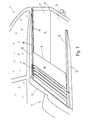
- FIG. 1 the broken-open rear section 1 of a station wagon is shown in perspective, the loading space 2 is delimited by a floor 3 and two side walls, of which only the right side wall 4 can be seen. Above the side wall 4 there is a rear side window 5, while the front end of the loading space 2 forms a rear seat back 6 of a rear seat bench 7.
- a cover roller blind 8 is provided, which is located just below the lower edge of the rear side window 5 and approximately at the level of the upper edge of the rear seat back 6.
- the cover blind 8 has two parallel and spaced straight guide rails 9 and 11, which are permanently attached to each of the two side walls 4 just below the lower edge of the adjacent side window 5.
- the guide rails 9 and 11 extend from the rear of the rear seat back 6 to a rear opening 12 of the car, which is to be closed by a loading flap (not shown).
- the space between the guide rails 9 and 11 and the outwardly convex side walls 4 is filled by appropriately adapted fillers 13.
- the guide rails 9 and 11 are used to guide six tubular struts, which are not recognizable because of the illustration in FIG. 1. In contrast, they can be seen in a reduced number in FIG. 2 and are provided with the reference symbols 14a to 14d.
- the tubular struts 14a to 14d carry a roller blind web 15, on the underside of which they are attached in an equidistantly distributed manner.
- the roller blind 15 is a rectangular and opaque plastic film blank, which may have a fabric reinforcement and the width of which is equal to the distance between the two guide rails 9 and 11 is, while the length of the cut corresponds to the distance of the back of the rear seat back 6 from the loading opening 12.
- the last strut 14a is connected to the edge of the roller blind 15 adjacent to the loading opening 12, while the strut 14d lying most forward in the car when the covering blind is inserted 8 is locked in the vicinity of the rear seat back 6.
- the roller blind 15 can be spread out over the loading space 2 in order to close off the loading space.
- the blind sheet 15 can also be pushed back in the direction of the rear seat back 6, the blind sheet 15 forming creases between the struts 14a to 14d when the struts are pushed together tightly. This is the gathered or fully opened state of the cover shade 8.
- the two guide rails 9 and 11 are in the same way installed in a longer, fixed in the motor vehicle Section 16 and a removable guide piece 17, which is located on both guide rails 9 and 11 in the vicinity of the rear seat back 6 and has a length which corresponds to the space required by the struts 14a to 14d with the roller blind 15 fully gathered.
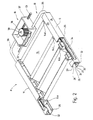
- FIG. 2 in which only the parts of the roller blind 8 necessary for the explanation are shown in a more schematic manner and in some cases enlarged disproportionately.
- a synchronizing device 18 is provided, the purpose of which is to determine the movement which one end of the strut 14a carries out, inevitably to the other end of this strut 14a, so that the perpendicular position of the strut 14a to the two parallel guide rails 9 and 11 is always maintained, even if the user to open and close the blind 8, the strut 14a only in the Touches near one of its two ends and moves in the guide rails 9 and 11.
- the synchronizing device 18 contains, as essential components, a transmission 19 and two flexible, longitudinally displaceable transmission members in the form of two racks 21 and 22.
- the structure is as follows:
- the guide rail 9 is a substantially longitudinally slotted square tube which is delimited by three closed sides 23, 24, 25.
- the closed side 24 is opposite a continuous slot 26 in the longitudinal direction of the guide rail 9, which is delimited at its two edges 27 and 28 by two inclined surfaces 29 and 31.
- the two inclined surfaces 29 and 31 converge in the shape of a funnel into the interior of the guide rail 9. This results in an approximately C-shaped cross-sectional profile, with the two guide rails 9 and 11 facing each other with their slots 26.
- a longitudinally slotted cylindrical tube 32 is formed on the inside of the side wall 24, the slot 33 of which extends approximately at the height of the center of the slot 26 and also extends over the entire length of the guide rail 9.
- the cylindrical tube 32 serves within the guide rail 9 as a guide for the toothed rack 22, which is made of a round plastic wire and is provided on its side facing the slot 33 with a toothing 34, for example an involute toothing.
- the gear 19 consists of a gear housing 37 in which a gear 38 is rotatably mounted.
- the gear housing 37 into which the two guide tubes 35 and 36 open, the two racks 21 and 22 are guided in such a way that they mesh with their toothing 34 with the gear 38, in two places which are located with respect to an axis of rotation 39 of the Gear 38 are diametrically opposite, that is, with reference to FIG. 2, the one rack 21 goes past the gear 38 on the right, while the rack 22 leads past the gear 38 on the left.
- the racks 21 and 22 must have a length of the toothing such that they can follow the full stroke of the strut 14a in the guide rails 9 and 11 without coming out of engagement with the gear 38 within the gear 19.
- the corresponding end of the strut 14a is provided with an approximately cuboidal guide piece 41 which, with its longitudinal extension, lies parallel to the longitudinal axis of the guide rail 9.
- the corresponding end of the strut 14a is provided with an approximately cuboidal guide piece 41 which, with its longitudinal extension, lies parallel to the longitudinal axis of the guide rail 9.
- two longitudinally running grooves 44, 45 which are V-shaped in cross section and which have a side surface complementary to the guide surfaces 31 and 29.
- a toothed rack section 47 is formed on the guide piece 41, which projects through the slot 33 and in the interior of the cylindrical slotted tube 32 with the toothing 34 of the toothed rack 22 or 21 located there engages in a form-fitting manner.
- a cylindrical pin 48 is formed on the guide piece 41, which extends into the interior of the tubular strut 14a. At a distance from the guide piece 41, the pin 48 is provided with a collar 49, the outer diameter of which corresponds approximately to the clear width of the strut 14a.
- annular disk 51 held there with a press fit, through the bore 52 of which the pin 48 extends, which is extended a little way beyond the annular disk 51.
- a helical compression spring 53 which surrounds the pin 48 and in this way biases the guide piece 41 in the direction of the guide rail 9, such that the corresponding flanks of the two grooves 44 and 45 to the Guide surfaces 29 and 31 are pressed.
- the rack section 47 engages in a form-fitting manner in the flexible rack 22.
- a ring 54 with an ore seat is inserted in its open end face, which at the same time guides the pin 48 between the collar 49 and the adjacent rear side of the guide piece 41 serves.
- the remaining struts 14b and 14c, possibly also the strut 14d, are provided with guide pieces 41 in the same way as in connection with the Brace 14a is described.
- the only difference is that the guide pieces 41 of the remaining struts do not have a rack section 47 and can therefore be displaced in the guide rail 9 or 11 independently of the flexible rack 22 or 21.
- the cover roller 8 described so far works as follows, it being initially assumed that the roller blind has the middle position shown in FIG. 2, in which the loading space 2 is partially covered. If, starting from this position, the user wants to close the loading space 2 completely, it suffices if, for example, he grasps the strut 14a at the right end and pulls it towards him. As a result of this movement of the strut 14a in the direction of the tailgate of the passenger car, the toothed rack 22 which is positively coupled to the guide piece 41 is carried inside the guide rail 9, ie it moves away from the transmission 19 with its corresponding end.
- the movement of the strut 14a is transmitted via the toothed rack 22 to the freely rotatable toothed wheel 38 which, in the assumed operating case, rotates counterclockwise because the toothed rack 22 is pulled past the toothed wheel 38 from left to right.
- the rotational movement of the gear 38 results in a corresponding movement of the rack 21, but in the opposite direction, because the rack 21 abuts the gear 38 on the other side, ie the rack 21 is moved by the gear 38 in the direction of the guide rail 11 advanced.
- This also moves the guide piece 41, which is in positive engagement with the rack 21, on the other side of the strut 14a in the direction of the tailgate of the car.
- the ratio between the two racks 21 and 22 is 1: 1. Accordingly, the two ends of the strut 14a always move at the same speed and by the same amount. The right-angled position of the strut 14a relative to the two guide rails 9 and 11 is therefore always maintained. Even if the application of force to actuate the strut 14a is extremely asymmetrical, the actuating force is transmitted to the other end of the strut 14a via the two racks 21 and 22 and the gearwheel 38 coupling the racks.
- a connection of the remaining struts 14b and 14c to the synchronizing device 19 is not necessary because their right-angled position relative to the guide rails 9 and 11 is inevitably maintained by the roller blind web 15, with which the strut is at least immovably connected in the transverse direction. If the area of the roller blind 15 located between the struts 14a and 14b is tightened, the strut 14b is pulled parallel to the strut 14a.
- the covering roller blind 8 can be partially removed, the guide rails 9 and 11 remaining together with the flexible toothed racks 21 and 22 in the vehicle . It will be when you take it out only the positive connection between the guide piece 41 and the corresponding racks 21, 22 separated. Since the toothing lies transversely to the longitudinal extent of the two guide rails 9, 11, it is readily possible to lift the two guide pieces 41 of the strut 14a upwards when the strut 14a is in the corresponding position.
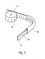
- perforated belts 57 which are stiff in compression and which contain a plurality of equidistantly distributed holes 58 over their length.
- the guide device has an approximately C-shaped shape, as is shown in the guide rail 59.
- a sprocket 61 is used as the gear 38 to produce the opposing movements of the two flexible transmission elements designed as perforated belts 57, which has a corresponding plurality of spikes 60 on its circumference corresponding to the division of the holes 58, which engage in the holes 58.
- FIG. 6 Another embodiment of the synchronization device 18 is shown in FIG. 6.
- a rack 62 is seated in the interior of the guide rail 9 over the underside 25.
- the rack 62 extends in the guide rail over the entire stroke which the strut 14a travels during the movement between the closed and the fully open position of the cover roller blind 8.
- the strut 14a is again designed as a tube and it is used to support a lead through it Shaft 63 which is rotatably supported at the two ends of the strut 14a in bearing pieces 64 which are inserted into the strut 14a.
- two pinions 65 are rotatably fitted, which mesh with the rack 62.
- the two pinions 65 roll on the associated racks 62. As described above, this also ensures that the other end of the strut 14a is also entrained if the strut 14a is only touched at one end during opening and closing and moved there by hand. The synchronized rolling movement of the pinion 65 inevitably also moves the other end of the strut 14a.
- the bearing pieces 64 can have a shape like the guide pieces 41 which are used in the struts 14b and 14c of the The aforementioned embodiment are explained, only with the difference that the pin 48 and the guide piece 41 are provided with through holes coaxial to the strut 14a, in which the shaft 63 is rotatably mounted.
Applications Claiming Priority (2)
| Application Number | Priority Date | Filing Date | Title |
|---|---|---|---|
| DE4016708A DE4016708C2 (de) | 1990-05-24 | 1990-05-24 | Abdeckung für den Laderaum eines PKW |
| DE4016708 | 1990-05-24 |
Publications (2)
| Publication Number | Publication Date |
|---|---|
| EP0459202A1 true EP0459202A1 (fr) | 1991-12-04 |
| EP0459202B1 EP0459202B1 (fr) | 1994-12-07 |
Family
ID=6407077
Family Applications (1)
| Application Number | Title | Priority Date | Filing Date |
|---|---|---|---|
| EP91107686A Expired - Lifetime EP0459202B1 (fr) | 1990-05-24 | 1991-05-11 | Rideau écran |
Country Status (3)
| Country | Link |
|---|---|
| EP (1) | EP0459202B1 (fr) |
| AT (1) | ATE115073T1 (fr) |
| DE (2) | DE4016708C2 (fr) |
Cited By (8)
| Publication number | Priority date | Publication date | Assignee | Title |
|---|---|---|---|---|
| DE19754223A1 (de) * | 1997-12-06 | 1999-06-10 | Volkswagen Ag | Gepäckraumabdeckung eines Fahrzeugs |
| WO2003008235A1 (fr) * | 2001-07-13 | 2003-01-30 | Daimlerchrysler Ag | Couverture d'espace de chargement entrainee par un moteur electrique |
| EP1334875A2 (fr) * | 2002-01-31 | 2003-08-13 | J. Stehle & Söhne Aktiengesellschaft | Unité d'entraínement pour déplacer un couvercle dans un véhicule automobile |
| EP1332919A3 (fr) * | 2002-01-31 | 2003-12-10 | BOS GmbH & Co. KG | Dispositif de maintien pour un espace de chargement de véhicule |
| EP1632396A1 (fr) * | 2004-08-05 | 2006-03-08 | Wilfried Boldt | Recouvrement destiné à l'espace de charge d'un véhicule automobile |
| ES2364262A1 (es) * | 2008-12-30 | 2011-08-30 | Grupo Antolin-Ingenieria, S.A. | Dispositivo de ocultación de una parte transparente de un techo de vehículo. |
| CN108302198A (zh) * | 2018-03-30 | 2018-07-20 | 法可赛(太仓)汽车配件有限公司 | 换挡驱动装置 |
| WO2021204307A1 (fr) * | 2020-04-06 | 2021-10-14 | Skoda Auto, A.S. | Poche de réception déplaçable située dans l'espace coffre d'un véhicule automobile |
Families Citing this family (3)
| Publication number | Priority date | Publication date | Assignee | Title |
|---|---|---|---|---|
| DE4202405C1 (fr) * | 1992-01-29 | 1993-04-29 | Mercedes-Benz Aktiengesellschaft, 7000 Stuttgart, De | |
| DE19646809B4 (de) * | 1996-11-13 | 2006-04-20 | Bayerische Motoren Werke Ag | Abdeckung |
| DE19825353C2 (de) * | 1997-06-17 | 2001-10-25 | Butz Peter Verwaltung | Laderaumabdeckung für Kraftfahrzeuge, insbesondere für Kombinations-Personenkraftwagen od. dgl. |
Citations (7)
| Publication number | Priority date | Publication date | Assignee | Title |
|---|---|---|---|---|
| DE2032144A1 (de) * | 1969-07-07 | 1971-03-25 | Regie Nationale des Usines Renault, Billancourt, Automobiles Peugeot, Paris, (Frankreich) | Betätigungsvorrichtung fur Fait schiebedach, insbesondere fur Kraftfahr zeuge |
| US4285539A (en) * | 1979-03-09 | 1981-08-25 | Cole Richard C | Retractable tonneau top |
| DE3310502A1 (de) * | 1983-03-23 | 1984-09-27 | Webasto-Werk W. Baier GmbH & Co, 8035 Gauting | Fuehrungsvorrichtung fuer ein schiebedach oder schiebehebedach mit mittelantrieb |
| DE3314444A1 (de) * | 1983-04-21 | 1984-10-25 | Eugen Otto 4010 Hilden Butz | Laderaumabdeckung fuer kraftwagen |
| DE3413966A1 (de) * | 1984-02-24 | 1985-10-03 | Siegfried 5042 Erftstadt Henschke | Sonnenschutz |
| US4756325A (en) * | 1985-11-01 | 1988-07-12 | Daniels Duane D | Collapsible canopy for pick-up trucks |
| WO1990002665A1 (fr) * | 1988-09-09 | 1990-03-22 | Sky-Top Sunroofs Ltd. | Toit ouvrant coulissant a position d'aeration |
Family Cites Families (3)
| Publication number | Priority date | Publication date | Assignee | Title |
|---|---|---|---|---|
| GB680551A (en) * | 1949-09-24 | 1952-10-08 | William Henry Bishop | Improvements in or relating to folding heads for cars |
| FR1181440A (fr) * | 1957-05-14 | 1959-06-16 | Hans Traugott Golde & Co G M B | Toit coulissant à commande électrique, notamment pour véhicules automobiles |
| DE3809949A1 (de) * | 1988-03-24 | 1989-10-05 | Webasto Ag Fahrzeugtechnik | Vorrichtung zum antrieb eines drucksteif gefuehrten antriebskabels |
-
1990
- 1990-05-24 DE DE4016708A patent/DE4016708C2/de not_active Expired - Fee Related
-
1991
- 1991-05-11 EP EP91107686A patent/EP0459202B1/fr not_active Expired - Lifetime
- 1991-05-11 AT AT91107686T patent/ATE115073T1/de not_active IP Right Cessation
- 1991-05-11 DE DE59103756T patent/DE59103756D1/de not_active Expired - Fee Related
Patent Citations (7)
| Publication number | Priority date | Publication date | Assignee | Title |
|---|---|---|---|---|
| DE2032144A1 (de) * | 1969-07-07 | 1971-03-25 | Regie Nationale des Usines Renault, Billancourt, Automobiles Peugeot, Paris, (Frankreich) | Betätigungsvorrichtung fur Fait schiebedach, insbesondere fur Kraftfahr zeuge |
| US4285539A (en) * | 1979-03-09 | 1981-08-25 | Cole Richard C | Retractable tonneau top |
| DE3310502A1 (de) * | 1983-03-23 | 1984-09-27 | Webasto-Werk W. Baier GmbH & Co, 8035 Gauting | Fuehrungsvorrichtung fuer ein schiebedach oder schiebehebedach mit mittelantrieb |
| DE3314444A1 (de) * | 1983-04-21 | 1984-10-25 | Eugen Otto 4010 Hilden Butz | Laderaumabdeckung fuer kraftwagen |
| DE3413966A1 (de) * | 1984-02-24 | 1985-10-03 | Siegfried 5042 Erftstadt Henschke | Sonnenschutz |
| US4756325A (en) * | 1985-11-01 | 1988-07-12 | Daniels Duane D | Collapsible canopy for pick-up trucks |
| WO1990002665A1 (fr) * | 1988-09-09 | 1990-03-22 | Sky-Top Sunroofs Ltd. | Toit ouvrant coulissant a position d'aeration |
Non-Patent Citations (1)
| Title |
|---|
| RESEARCH DISCLOSURE. no. 227, März 1983, HAVANT GB Seiten 108 - 110; "DYMETROL ELASTOMERIC TAPE DRIVES AUTOMOTIVE ENERGY TRANSFER SYSTEMS" * |
Cited By (10)
| Publication number | Priority date | Publication date | Assignee | Title |
|---|---|---|---|---|
| DE19754223A1 (de) * | 1997-12-06 | 1999-06-10 | Volkswagen Ag | Gepäckraumabdeckung eines Fahrzeugs |
| WO2003008235A1 (fr) * | 2001-07-13 | 2003-01-30 | Daimlerchrysler Ag | Couverture d'espace de chargement entrainee par un moteur electrique |
| EP1334875A2 (fr) * | 2002-01-31 | 2003-08-13 | J. Stehle & Söhne Aktiengesellschaft | Unité d'entraínement pour déplacer un couvercle dans un véhicule automobile |
| EP1332919A3 (fr) * | 2002-01-31 | 2003-12-10 | BOS GmbH & Co. KG | Dispositif de maintien pour un espace de chargement de véhicule |
| EP1334875A3 (fr) * | 2002-01-31 | 2004-12-08 | J. Stehle & Söhne Aktiengesellschaft | Unité d'entraínement pour déplacer un couvercle dans un véhicule automobile |
| US7028872B2 (en) | 2002-01-31 | 2006-04-18 | Bos Gmbh & Co. Kg | Storage device for a cargo space for a motor vehicle |
| EP1632396A1 (fr) * | 2004-08-05 | 2006-03-08 | Wilfried Boldt | Recouvrement destiné à l'espace de charge d'un véhicule automobile |
| ES2364262A1 (es) * | 2008-12-30 | 2011-08-30 | Grupo Antolin-Ingenieria, S.A. | Dispositivo de ocultación de una parte transparente de un techo de vehículo. |
| CN108302198A (zh) * | 2018-03-30 | 2018-07-20 | 法可赛(太仓)汽车配件有限公司 | 换挡驱动装置 |
| WO2021204307A1 (fr) * | 2020-04-06 | 2021-10-14 | Skoda Auto, A.S. | Poche de réception déplaçable située dans l'espace coffre d'un véhicule automobile |
Also Published As
| Publication number | Publication date |
|---|---|
| DE4016708C2 (de) | 1994-07-21 |
| DE4016708A1 (de) | 1991-11-28 |
| ATE115073T1 (de) | 1994-12-15 |
| EP0459202B1 (fr) | 1994-12-07 |
| DE59103756D1 (de) | 1995-01-19 |
Similar Documents
| Publication | Publication Date | Title |
|---|---|---|
| EP1375219B1 (fr) | Store à enrouleur pour lunette arrière avec boîtier levant | |
| EP1550570B1 (fr) | Store à enrouler divisé pour une fenêtre de véhicule | |
| EP1609647B1 (fr) | Store à enrouler avec couvercle sur la fente extracte | |
| EP1211109B1 (fr) | Store à enrouler avec dispositif de centrage pour la tige de tension | |
| DE102005029559B4 (de) | Heckfensterrollo mit vollständiger Schlitzabdeckung durch das Auszugsprofil | |
| EP1209013B1 (fr) | Vitre avec store à enrouleur attaché | |
| EP2039547B1 (fr) | Store de fenêtre latérale doté d'une aide à l'introduction | |
| DE3608927A1 (de) | Blendschutzeinrichtung fuer ein fahrzeug | |
| DE2263291C3 (de) | Passive Sicherheitsgurtsystem | |
| EP1495888A1 (fr) | Pare-soleil pour toit de véhicule | |
| EP0459202A1 (fr) | Rideau écran | |
| DE4016707A1 (de) | Elektrisches abdeckrollo | |
| DE2641243C2 (de) | Sitz, insbesondere Fahrzeugsitz | |
| EP0787627B1 (fr) | Véhicule automobile avec au moins un rouleau de protection | |
| DE19930049C2 (de) | Eine oberhalb des Windschutzscheibenrahmens von Personenkraftwagen angeordnete Abschirmvorrichtung | |
| DE2507893A1 (de) | Fensterheber fuer vertikal unterteilte kraftfahrzeugschiebefenster | |
| EP1986876B1 (fr) | Dispositif d'obscurcissement pour une vitre transparente, notamment pour vehicules automobiles | |
| EP1738942B1 (fr) | Store à enrouleur pour véhicule automobile muni d'une butée de contact fixée rigidement sur un actionneur | |
| DE3301309C2 (de) | Verstellvorrichtung für Fahrzeug-Sitze | |
| DE102007035072A1 (de) | Rollo für ein Kraftfahrzeugseitenfenster mit Fensterteilungssteg | |
| DE102014003440B3 (de) | Laderaumabdeckung für ein Fahrzeug | |
| DE3606132C2 (fr) | ||
| DE3211467C2 (de) | Öffnungssystem für Schiebedach, insbesondere für Kraftfahrzeuge | |
| DE3713028C2 (fr) | ||
| EP3513995B1 (fr) | Dispositif formant bâche roulante pour un corps en forme d'auge d'un véhicule utilitaire |
Legal Events
| Date | Code | Title | Description |
|---|---|---|---|
| PUAI | Public reference made under article 153(3) epc to a published international application that has entered the european phase |
Free format text: ORIGINAL CODE: 0009012 |
|
| AK | Designated contracting states |
Kind code of ref document: A1 Designated state(s): AT BE CH DE DK ES FR GB GR IT LI LU NL SE |
|
| 17P | Request for examination filed |
Effective date: 19920130 |
|
| 17Q | First examination report despatched |
Effective date: 19930609 |
|
| GRAA | (expected) grant |
Free format text: ORIGINAL CODE: 0009210 |
|
| AK | Designated contracting states |
Kind code of ref document: B1 Designated state(s): AT BE CH DE DK ES FR GB GR IT LI LU NL SE |
|
| PG25 | Lapsed in a contracting state [announced via postgrant information from national office to epo] |
Ref country code: NL Effective date: 19941207 Ref country code: GR Free format text: LAPSE BECAUSE OF FAILURE TO SUBMIT A TRANSLATION OF THE DESCRIPTION OR TO PAY THE FEE WITHIN THE PRESCRIBED TIME-LIMIT Effective date: 19941207 Ref country code: ES Free format text: THE PATENT HAS BEEN ANNULLED BY A DECISION OF A NATIONAL AUTHORITY Effective date: 19941207 Ref country code: DK Effective date: 19941207 Ref country code: BE Effective date: 19941207 |
|
| REF | Corresponds to: |
Ref document number: 115073 Country of ref document: AT Date of ref document: 19941215 Kind code of ref document: T |
|
| ET | Fr: translation filed | ||
| GBT | Gb: translation of ep patent filed (gb section 77(6)(a)/1977) |
Effective date: 19941214 |
|
| REF | Corresponds to: |
Ref document number: 59103756 Country of ref document: DE Date of ref document: 19950119 |
|
| ITF | It: translation for a ep patent filed |
Owner name: JACOBACCI & PERANI S.P.A. |
|
| PG25 | Lapsed in a contracting state [announced via postgrant information from national office to epo] |
Ref country code: SE Effective date: 19950307 |
|
| PG25 | Lapsed in a contracting state [announced via postgrant information from national office to epo] |
Ref country code: AT Effective date: 19950511 |
|
| NLV1 | Nl: lapsed or annulled due to failure to fulfill the requirements of art. 29p and 29m of the patents act | ||
| PG25 | Lapsed in a contracting state [announced via postgrant information from national office to epo] |
Ref country code: LU Free format text: LAPSE BECAUSE OF NON-PAYMENT OF DUE FEES Effective date: 19950531 Ref country code: LI Effective date: 19950531 Ref country code: CH Effective date: 19950531 |
|
| PLBE | No opposition filed within time limit |
Free format text: ORIGINAL CODE: 0009261 |
|
| STAA | Information on the status of an ep patent application or granted ep patent |
Free format text: STATUS: NO OPPOSITION FILED WITHIN TIME LIMIT |
|
| 26N | No opposition filed | ||
| REG | Reference to a national code |
Ref country code: CH Ref legal event code: PL |
|
| REG | Reference to a national code |
Ref country code: GB Ref legal event code: IF02 |
|
| PGFP | Annual fee paid to national office [announced via postgrant information from national office to epo] |
Ref country code: GB Payment date: 20030428 Year of fee payment: 13 |
|
| PGFP | Annual fee paid to national office [announced via postgrant information from national office to epo] |
Ref country code: FR Payment date: 20030512 Year of fee payment: 13 |
|
| PGFP | Annual fee paid to national office [announced via postgrant information from national office to epo] |
Ref country code: DE Payment date: 20030531 Year of fee payment: 13 |
|
| PG25 | Lapsed in a contracting state [announced via postgrant information from national office to epo] |
Ref country code: GB Free format text: LAPSE BECAUSE OF NON-PAYMENT OF DUE FEES Effective date: 20040511 |
|
| PG25 | Lapsed in a contracting state [announced via postgrant information from national office to epo] |
Ref country code: DE Free format text: LAPSE BECAUSE OF NON-PAYMENT OF DUE FEES Effective date: 20041201 |
|
| GBPC | Gb: european patent ceased through non-payment of renewal fee |
Effective date: 20040511 |
|
| PG25 | Lapsed in a contracting state [announced via postgrant information from national office to epo] |
Ref country code: FR Free format text: LAPSE BECAUSE OF NON-PAYMENT OF DUE FEES Effective date: 20050131 |
|
| REG | Reference to a national code |
Ref country code: FR Ref legal event code: ST |
|
| PG25 | Lapsed in a contracting state [announced via postgrant information from national office to epo] |
Ref country code: IT Free format text: LAPSE BECAUSE OF NON-PAYMENT OF DUE FEES;WARNING: LAPSES OF ITALIAN PATENTS WITH EFFECTIVE DATE BEFORE 2007 MAY HAVE OCCURRED AT ANY TIME BEFORE 2007. THE CORRECT EFFECTIVE DATE MAY BE DIFFERENT FROM THE ONE RECORDED. Effective date: 20050511 |