EP0459202A1 - Roller blind - Google Patents
Roller blind Download PDFInfo
- Publication number
- EP0459202A1 EP0459202A1 EP91107686A EP91107686A EP0459202A1 EP 0459202 A1 EP0459202 A1 EP 0459202A1 EP 91107686 A EP91107686 A EP 91107686A EP 91107686 A EP91107686 A EP 91107686A EP 0459202 A1 EP0459202 A1 EP 0459202A1
- Authority
- EP
- European Patent Office
- Prior art keywords
- strut
- roller blind
- cover
- gear
- guide
- Prior art date
- Legal status (The legal status is an assumption and is not a legal conclusion. Google has not performed a legal analysis and makes no representation as to the accuracy of the status listed.)
- Granted
Links
Images


Classifications
-
- B—PERFORMING OPERATIONS; TRANSPORTING
- B60—VEHICLES IN GENERAL
- B60R—VEHICLES, VEHICLE FITTINGS, OR VEHICLE PARTS, NOT OTHERWISE PROVIDED FOR
- B60R5/00—Compartments within vehicle body primarily intended or sufficiently spacious for trunks, suit-cases, or the like
- B60R5/04—Compartments within vehicle body primarily intended or sufficiently spacious for trunks, suit-cases, or the like arranged at rear of vehicle
- B60R5/044—Compartments within vehicle body primarily intended or sufficiently spacious for trunks, suit-cases, or the like arranged at rear of vehicle luggage covering means, e.g. parcel shelves
- B60R5/045—Compartments within vehicle body primarily intended or sufficiently spacious for trunks, suit-cases, or the like arranged at rear of vehicle luggage covering means, e.g. parcel shelves collapsible or transformable
- B60R5/048—Compartments within vehicle body primarily intended or sufficiently spacious for trunks, suit-cases, or the like arranged at rear of vehicle luggage covering means, e.g. parcel shelves collapsible or transformable of accordion-type, i.e. collapsible by sliding and folding
Definitions
- the invention relates to a roller blind for the loading space of a car, with the features of the preamble of claim 1.
- the known roller blind has a roller blind which is supported by a plurality of struts running parallel to one another.
- the struts run at the end in two mutually parallel guide rails which are attached above the access opening of the storage space in the body.
- each strut there is a spring-loaded slide which slides in the guide rail, which is approximately C-shaped in cross section.
- the spring-preloaded sliders which have one end in the associated tubular strut, on the one hand prevent the struts from rattling in the guides and, on the other hand, prevent the struts from jamming to a certain extent when the blind is pushed together by hand.
- the prerequisite for this, however, is that the struts for opening the blind are gripped and pushed approximately in the middle of their longitudinal extent. If, however, an attempt is made to open the roller blind by moving the strut only near one of its ends, the spring preloaded sliders cannot prevent jamming.
- cover roller blind according to the invention is characterized by the features of claim 1.
- the synchronizing device automatically transfers the movement at one end of the strut to the other end of the strut so that it is guided in synchronism with the actuated end.
- the strut can no longer tilt and jam between the guide rails.
- the transmission elements which transmit the movement are flexible and lie essentially in or near the guide rails, and are coupled to one another in terms of movement by a transmission at their end remote from the synchronized strut.
- the transmission members which are also provided on or in the guide rails, are rigid and immobile, while in the synchronized strut there is a shaft which carries pinions at both ends, with which it positively engages in the rigidly and immovably arranged transmission members intervenes.
- the transmission for coupling the movement of the flexible transmission members consists of a gearwheel which has a toothing which is complementary to the toothing of the movable transmission members and with which the two transmission members are in engagement at diametrically opposite points.
- the strut connected to the synchronizing device has releasable coupling means for connecting to the gear elements or, when using pinions in connection with permanently installed racks, is easily detachable from these anyway.
- the coupling means with the case of the movable, flexible gear means consist of the same toothing with which the gear means engage the coupling gear.
- the strut assigned to the synchronizing device contains at least at one end an axially displaceable end piece which is biased by a spring into the engagement position with the flexible transmission means.
- Rattling of the strut in the guide rails is largely avoided if the guide rails, which are approximately C-shaped in cross section, carry guide surfaces in the region of their longitudinal slot, which converge towards the interior of the guide rail and the struts are provided with spring-loaded end pieces which are complementary to this.
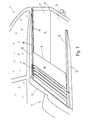
- FIG. 1 the broken-open rear section 1 of a station wagon is shown in perspective, the loading space 2 is delimited by a floor 3 and two side walls, of which only the right side wall 4 can be seen. Above the side wall 4 there is a rear side window 5, while the front end of the loading space 2 forms a rear seat back 6 of a rear seat bench 7.
- a cover roller blind 8 is provided, which is located just below the lower edge of the rear side window 5 and approximately at the level of the upper edge of the rear seat back 6.
- the cover blind 8 has two parallel and spaced straight guide rails 9 and 11, which are permanently attached to each of the two side walls 4 just below the lower edge of the adjacent side window 5.
- the guide rails 9 and 11 extend from the rear of the rear seat back 6 to a rear opening 12 of the car, which is to be closed by a loading flap (not shown).
- the space between the guide rails 9 and 11 and the outwardly convex side walls 4 is filled by appropriately adapted fillers 13.
- the guide rails 9 and 11 are used to guide six tubular struts, which are not recognizable because of the illustration in FIG. 1. In contrast, they can be seen in a reduced number in FIG. 2 and are provided with the reference symbols 14a to 14d.
- the tubular struts 14a to 14d carry a roller blind web 15, on the underside of which they are attached in an equidistantly distributed manner.
- the roller blind 15 is a rectangular and opaque plastic film blank, which may have a fabric reinforcement and the width of which is equal to the distance between the two guide rails 9 and 11 is, while the length of the cut corresponds to the distance of the back of the rear seat back 6 from the loading opening 12.
- the last strut 14a is connected to the edge of the roller blind 15 adjacent to the loading opening 12, while the strut 14d lying most forward in the car when the covering blind is inserted 8 is locked in the vicinity of the rear seat back 6.
- the roller blind 15 can be spread out over the loading space 2 in order to close off the loading space.
- the blind sheet 15 can also be pushed back in the direction of the rear seat back 6, the blind sheet 15 forming creases between the struts 14a to 14d when the struts are pushed together tightly. This is the gathered or fully opened state of the cover shade 8.
- the two guide rails 9 and 11 are in the same way installed in a longer, fixed in the motor vehicle Section 16 and a removable guide piece 17, which is located on both guide rails 9 and 11 in the vicinity of the rear seat back 6 and has a length which corresponds to the space required by the struts 14a to 14d with the roller blind 15 fully gathered.
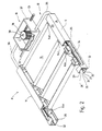
- FIG. 2 in which only the parts of the roller blind 8 necessary for the explanation are shown in a more schematic manner and in some cases enlarged disproportionately.
- a synchronizing device 18 is provided, the purpose of which is to determine the movement which one end of the strut 14a carries out, inevitably to the other end of this strut 14a, so that the perpendicular position of the strut 14a to the two parallel guide rails 9 and 11 is always maintained, even if the user to open and close the blind 8, the strut 14a only in the Touches near one of its two ends and moves in the guide rails 9 and 11.
- the synchronizing device 18 contains, as essential components, a transmission 19 and two flexible, longitudinally displaceable transmission members in the form of two racks 21 and 22.
- the structure is as follows:
- the guide rail 9 is a substantially longitudinally slotted square tube which is delimited by three closed sides 23, 24, 25.
- the closed side 24 is opposite a continuous slot 26 in the longitudinal direction of the guide rail 9, which is delimited at its two edges 27 and 28 by two inclined surfaces 29 and 31.
- the two inclined surfaces 29 and 31 converge in the shape of a funnel into the interior of the guide rail 9. This results in an approximately C-shaped cross-sectional profile, with the two guide rails 9 and 11 facing each other with their slots 26.
- a longitudinally slotted cylindrical tube 32 is formed on the inside of the side wall 24, the slot 33 of which extends approximately at the height of the center of the slot 26 and also extends over the entire length of the guide rail 9.
- the cylindrical tube 32 serves within the guide rail 9 as a guide for the toothed rack 22, which is made of a round plastic wire and is provided on its side facing the slot 33 with a toothing 34, for example an involute toothing.
- the gear 19 consists of a gear housing 37 in which a gear 38 is rotatably mounted.
- the gear housing 37 into which the two guide tubes 35 and 36 open, the two racks 21 and 22 are guided in such a way that they mesh with their toothing 34 with the gear 38, in two places which are located with respect to an axis of rotation 39 of the Gear 38 are diametrically opposite, that is, with reference to FIG. 2, the one rack 21 goes past the gear 38 on the right, while the rack 22 leads past the gear 38 on the left.
- the racks 21 and 22 must have a length of the toothing such that they can follow the full stroke of the strut 14a in the guide rails 9 and 11 without coming out of engagement with the gear 38 within the gear 19.
- the corresponding end of the strut 14a is provided with an approximately cuboidal guide piece 41 which, with its longitudinal extension, lies parallel to the longitudinal axis of the guide rail 9.
- the corresponding end of the strut 14a is provided with an approximately cuboidal guide piece 41 which, with its longitudinal extension, lies parallel to the longitudinal axis of the guide rail 9.
- two longitudinally running grooves 44, 45 which are V-shaped in cross section and which have a side surface complementary to the guide surfaces 31 and 29.
- a toothed rack section 47 is formed on the guide piece 41, which projects through the slot 33 and in the interior of the cylindrical slotted tube 32 with the toothing 34 of the toothed rack 22 or 21 located there engages in a form-fitting manner.
- a cylindrical pin 48 is formed on the guide piece 41, which extends into the interior of the tubular strut 14a. At a distance from the guide piece 41, the pin 48 is provided with a collar 49, the outer diameter of which corresponds approximately to the clear width of the strut 14a.
- annular disk 51 held there with a press fit, through the bore 52 of which the pin 48 extends, which is extended a little way beyond the annular disk 51.
- a helical compression spring 53 which surrounds the pin 48 and in this way biases the guide piece 41 in the direction of the guide rail 9, such that the corresponding flanks of the two grooves 44 and 45 to the Guide surfaces 29 and 31 are pressed.
- the rack section 47 engages in a form-fitting manner in the flexible rack 22.
- a ring 54 with an ore seat is inserted in its open end face, which at the same time guides the pin 48 between the collar 49 and the adjacent rear side of the guide piece 41 serves.
- the remaining struts 14b and 14c, possibly also the strut 14d, are provided with guide pieces 41 in the same way as in connection with the Brace 14a is described.
- the only difference is that the guide pieces 41 of the remaining struts do not have a rack section 47 and can therefore be displaced in the guide rail 9 or 11 independently of the flexible rack 22 or 21.
- the cover roller 8 described so far works as follows, it being initially assumed that the roller blind has the middle position shown in FIG. 2, in which the loading space 2 is partially covered. If, starting from this position, the user wants to close the loading space 2 completely, it suffices if, for example, he grasps the strut 14a at the right end and pulls it towards him. As a result of this movement of the strut 14a in the direction of the tailgate of the passenger car, the toothed rack 22 which is positively coupled to the guide piece 41 is carried inside the guide rail 9, ie it moves away from the transmission 19 with its corresponding end.
- the movement of the strut 14a is transmitted via the toothed rack 22 to the freely rotatable toothed wheel 38 which, in the assumed operating case, rotates counterclockwise because the toothed rack 22 is pulled past the toothed wheel 38 from left to right.
- the rotational movement of the gear 38 results in a corresponding movement of the rack 21, but in the opposite direction, because the rack 21 abuts the gear 38 on the other side, ie the rack 21 is moved by the gear 38 in the direction of the guide rail 11 advanced.
- This also moves the guide piece 41, which is in positive engagement with the rack 21, on the other side of the strut 14a in the direction of the tailgate of the car.
- the ratio between the two racks 21 and 22 is 1: 1. Accordingly, the two ends of the strut 14a always move at the same speed and by the same amount. The right-angled position of the strut 14a relative to the two guide rails 9 and 11 is therefore always maintained. Even if the application of force to actuate the strut 14a is extremely asymmetrical, the actuating force is transmitted to the other end of the strut 14a via the two racks 21 and 22 and the gearwheel 38 coupling the racks.
- a connection of the remaining struts 14b and 14c to the synchronizing device 19 is not necessary because their right-angled position relative to the guide rails 9 and 11 is inevitably maintained by the roller blind web 15, with which the strut is at least immovably connected in the transverse direction. If the area of the roller blind 15 located between the struts 14a and 14b is tightened, the strut 14b is pulled parallel to the strut 14a.
- the covering roller blind 8 can be partially removed, the guide rails 9 and 11 remaining together with the flexible toothed racks 21 and 22 in the vehicle . It will be when you take it out only the positive connection between the guide piece 41 and the corresponding racks 21, 22 separated. Since the toothing lies transversely to the longitudinal extent of the two guide rails 9, 11, it is readily possible to lift the two guide pieces 41 of the strut 14a upwards when the strut 14a is in the corresponding position.
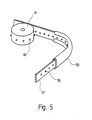
- perforated belts 57 which are stiff in compression and which contain a plurality of equidistantly distributed holes 58 over their length.
- the guide device has an approximately C-shaped shape, as is shown in the guide rail 59.
- a sprocket 61 is used as the gear 38 to produce the opposing movements of the two flexible transmission elements designed as perforated belts 57, which has a corresponding plurality of spikes 60 on its circumference corresponding to the division of the holes 58, which engage in the holes 58.
- FIG. 6 Another embodiment of the synchronization device 18 is shown in FIG. 6.
- a rack 62 is seated in the interior of the guide rail 9 over the underside 25.
- the rack 62 extends in the guide rail over the entire stroke which the strut 14a travels during the movement between the closed and the fully open position of the cover roller blind 8.
- the strut 14a is again designed as a tube and it is used to support a lead through it Shaft 63 which is rotatably supported at the two ends of the strut 14a in bearing pieces 64 which are inserted into the strut 14a.
- two pinions 65 are rotatably fitted, which mesh with the rack 62.
- the two pinions 65 roll on the associated racks 62. As described above, this also ensures that the other end of the strut 14a is also entrained if the strut 14a is only touched at one end during opening and closing and moved there by hand. The synchronized rolling movement of the pinion 65 inevitably also moves the other end of the strut 14a.
- the bearing pieces 64 can have a shape like the guide pieces 41 which are used in the struts 14b and 14c of the The aforementioned embodiment are explained, only with the difference that the pin 48 and the guide piece 41 are provided with through holes coaxial to the strut 14a, in which the shaft 63 is rotatably mounted.
Abstract
Description
Die Erfindung betrifft ein Abdeckrollo für den Laderaum eines PKW, mit den Merkmalen des Oberbegriffs des Anspruches 1.The invention relates to a roller blind for the loading space of a car, with the features of the preamble of claim 1.
Aus der DE-PS 38 19 766 ist ein Abdeckrollo für den Lade- oder Kofferraum, insbesondere von Kombi-PKW beschrieben. Das bekannte Rollo weist eine Rollobahn auf, die von mehreren, parallel zueinander verlaufenden Streben getragen ist. Die Streben laufen endseitig in zwei parallel zueinander sich erstreckenden Führungsschienen, die oberhalb der Zugangsöffnung des Stauraums in der Karosserie angebracht sind.From DE-PS 38 19 766 a cover roller blind for the cargo or trunk, in particular of estate cars is described. The known roller blind has a roller blind which is supported by a plurality of struts running parallel to one another. The struts run at the end in two mutually parallel guide rails which are attached above the access opening of the storage space in the body.
Jede Strebe enthält endseitig ein federvorgespanntes Gleitstück, das in der im Querschnitt etwa C-förmigen Führungsschiene gleitet. Die federvorgespannten Gleitstücke, die mit einem Ende in der zugehörigen rohrförmigen Strebe stecken, verhindern einerseits ein Klappern der Streben in den Führungen und andererseits beugen sie bis zu einem gewissen Grad einem Verklemmen der Streben vor, wenn das Rollo von Hand zusammengeschoben wird. Voraussetzung dafür ist allerdings, daß die Streben zum öffnen des Rollos etwa in der Mitte ihrer Längserstreckung angefaßt und geschoben werden. Wenn allerdings versucht wird, das Rollo zu öffnen, indem die Strebe nur in der Nähe eines ihrer Enden bewegt wird, können Klemmerscheinungen auch durch die federvorbelasteten Gleitstücke nicht verhindert werden.At the end of each strut there is a spring-loaded slide which slides in the guide rail, which is approximately C-shaped in cross section. The spring-preloaded sliders, which have one end in the associated tubular strut, on the one hand prevent the struts from rattling in the guides and, on the other hand, prevent the struts from jamming to a certain extent when the blind is pushed together by hand. The prerequisite for this, however, is that the struts for opening the blind are gripped and pushed approximately in the middle of their longitudinal extent. If, however, an attempt is made to open the roller blind by moving the strut only near one of its ends, the spring preloaded sliders cannot prevent jamming.
Ausgehend hiervon ist es Aufgabe der Erfindung, ein Abdeckrollo zu schaffen, das auch dann nicht klemmt, wenn zum öffnen die dem Benutzer unmittelbar benachbarte Strebe nur an einem Ende betätigt wird.Proceeding from this, it is an object of the invention to provide a cover roller blind that does not jam even when the strut that is directly adjacent to the user is actuated only at one end to open it.
Zur Lösung dieser Aufgabe ist das erfindungsgemäße Abdeckrollo durch die Merkmale des Anspruches 1 gekennzeichnet.To solve this problem, the cover roller blind according to the invention is characterized by the features of claim 1.
Die Synchronisiereinrichtung überträgt die Bewegung an einem Ende der betätigten Strebe selbsttätig auf das andere Ende der Strebe, so daß es synchron mit dem betätigten Ende geführt wird. Die Strebe kann sich zwischen den Führungsschienen nicht mehr schrägstellen und verklemmen.The synchronizing device automatically transfers the movement at one end of the strut to the other end of the strut so that it is guided in synchronism with the actuated end. The strut can no longer tilt and jam between the guide rails.
Da in aller Regel der Benutzer nur jene Strebe bedient, die ihm unmittelbar benachbart ist, genügt es, wenn lediglich die Strebe, die beim öffnen oder schließen der Abdeckung den größten Weg zurücklegt, mit der Synchronisiereinrichtung versehen ist.Since the user generally only operates the strut that is directly adjacent to him, it is sufficient if only the strut, which covers the greatest distance when opening or closing the cover, is provided with the synchronizing device.
Für die Synchronisiereinrichtung kommen grundsätzlich zwei unterschiedliche Ausführungen in Frage. Bei der einen Ausführung sind die Getriebeglieder, die die Bewegung übertragen, flexibel und liegen im wesentlichen in oder in der Nähe der Führungsschienen, wobei sie an ihrem von der synchronisierten Strebe abliegenden Ende durch ein Getriebe bewegungsmäßig miteinander gekoppelt sind. Bei der anderen Ausführungsform sind die Getriebeglieder, die ebenfalls an oder in den Führungsschienen vorgesehen sind, starr und ortsunveränderlich, während in der synchronisierten Strebe eine Welle verläuft, die an ihren beiden Enden Ritzel trägt, mit denen sie formschlüssig in die starr und ortsunveränderlich angeordneten Getriebeglieder eingreift.There are basically two different designs for the synchronization device. In one embodiment, the transmission elements which transmit the movement are flexible and lie essentially in or near the guide rails, and are coupled to one another in terms of movement by a transmission at their end remote from the synchronized strut. In the other embodiment, the transmission members, which are also provided on or in the guide rails, are rigid and immobile, while in the synchronized strut there is a shaft which carries pinions at both ends, with which it positively engages in the rigidly and immovably arranged transmission members intervenes.
Im Fall der biegsamen Getriebeglieder, die sich beim öffnen und Schließen des Abdeckrollos bewegen, können hierzu biegsame Zahnstangen oder Lochbänder verwendet werden. Das Getriebe zum Koppeln der Bewegung der biegsamen Getriebeglieder besteht im einfachsten Falle aus einem Zahnrad, das eine zu der Verzahnung der beweglichen Getriebeglieder komplementäre Verzahnung trägt und mit dem die beiden Getriebeglieder an diametral gegenüberliegenden Stellen in Eingriff steht.In the case of the flexible gear links that move when the roller blind is opened and closed, flexible racks or perforated strips can be used for this. In the simplest case, the transmission for coupling the movement of the flexible transmission members consists of a gearwheel which has a toothing which is complementary to the toothing of the movable transmission members and with which the two transmission members are in engagement at diametrically opposite points.
Wenn als bewegliche Getriebeglieder dünne Bänder oder Stangen verwendet werden, ist es zweckmäßig, die Getriebeglieder in Führungseinrichtungen drucksteif zu führen, um ein seitliches Ausknicken bei Druckbelastung zu verhindern.If thin belts or rods are used as movable gear links, it is expedient to guide the gear links in guide devices so that they are pressure-resistant in order to prevent them from buckling under pressure.
Auch bei den neuen Abdeckrollo ist es möglich, eine benutzerseitige Demontierbarkeit vorzusehen. Zu diesem Zweck verfügt die mit der Synchronisiereinrichtung verbundene Strebe über lösbare Kupplungsmittel zum Verbinden mit den Getriebeelementen bzw. ist bei der Verwendung von Ritzeln in Verbindung mit festverlegten Zahnstangen ohnehin leicht von diesen lösbar. Vorteilhafterweise bestehen die Kupplungsmittel mit Falle der beweglichen biegsamen Getriebemittel aus derselben Verzahnung, mit denen die Getriebemittel mit dem Kopplungszahnrad in Eingriff stehen. Im einfachsten Falle enthält die der Synchronisiereinrichtung zugeordnete Strebe zumindest an einem Ende ein axial verschiebliches Endstück, das durch eine Feder in die Eingriffsstellung mit dem biegsamen Getriebemittel zu vorgespannt ist.With the new cover roller blind, it is also possible to provide for dismantling by the user. For this purpose, the strut connected to the synchronizing device has releasable coupling means for connecting to the gear elements or, when using pinions in connection with permanently installed racks, is easily detachable from these anyway. Advantageously, the coupling means with the case of the movable, flexible gear means consist of the same toothing with which the gear means engage the coupling gear. In the simplest case, the strut assigned to the synchronizing device contains at least at one end an axially displaceable end piece which is biased by a spring into the engagement position with the flexible transmission means.
Ein Klappern der Strebe in den Führungsschienen wird weitgehend vermieden, wenn die im Querschnitt etwa C-förmigen Führungsschienen im Bereich ihres Längsschlitzes Führungsflächen tragen, die in Richtung auf das Innere der Führungsschiene konvergieren und die Streben mit federvorgespannten Endstücken versehen sind, die hierzu komplementär sind.Rattling of the strut in the guide rails is largely avoided if the guide rails, which are approximately C-shaped in cross section, carry guide surfaces in the region of their longitudinal slot, which converge towards the interior of the guide rail and the struts are provided with spring-loaded end pieces which are complementary to this.
In der Zeichnung sind Ausführungsbeispiele des Gegenstandes der Erfindung dargestellt. Es zeigen:
- Fig. 1
- ein über dem Laderaum eines Kombiwagens angeordnetes, teilweise ausgezogenes Abdeckrollo gemäß der Erfindung in einer perspektivischen Darstellung, wobei eine Seitenwand des PKW weggebrochen ist,
- Fig. 2
- die Synchronisiereinrichtung des Abdeckrollos nach Fig. 1 in einer stark schematisierten perspektivischen Darstellung,
- Fig. 3
- die mit der Synchronisiereinrichtung gekoppelte Strebe des Abdeckrollos nach Fig. 1 in einem Schnitt durch eines ihrer Enden,
- Fig. 4
- die Strebe nach Fig. 3 in einer Draufsicht,
- Fig. 5
- ein Lochband für die Synchronisiereinrichtung nach Fig. 2 in schematischer perspektivischer Darstellung und
- Fig. 6
- eine andere Synchronisiereinrichtung für das Abdeckrollo nach Fig. 1, ebenfalls in einer stark schematisierten perspektivischen Darstellung.
- Fig. 1
- a perspective view of a partially extended cover roller blind arranged above the loading space of a station wagon, a side wall of the car having broken away,
- Fig. 2
- 1 in a highly schematic perspective view,
- Fig. 3
- 1 in a section through one of its ends, the strut of the roller blind according to FIG. 1 coupled to the synchronizing device,
- Fig. 4
- 3 in a top view,
- Fig. 5
- a perforated tape for the synchronization device of FIG. 2 in a schematic perspective view and
- Fig. 6
- another synchronizing device for the cover roller blind according to FIG. 1, also in a highly schematic perspective representation.
In Fig. 1 ist die aufgebrochen dargestellte Heckpartie 1 eines Kombiwagens perspektivisch veranschaulicht, dessen Laderaum 2 von einem Boden 3 sowie zwei Seitenwänden begrenzt ist, von denen nur die rechte Seitenwand 4 erkennbar ist. Über der Seitenwand 4 befindet sich ein hinteres Seitenfenster 5, während den vorderen Abschluß des Laderaumes 2 eine Rücksitzlehne 6 einer Rücksitzbank 7 bildet.In Fig. 1, the broken-open rear section 1 of a station wagon is shown in perspective, the
Zum Abdecken des Laderaums 2 ist ein Abdeckrollo 8 vorgesehen, das sich knapp unterhalb der Unterkante des hinteren Seitenfensters 5 und etwa auf Höhe der Oberkante der Rücksitzlehne 6 befindet. Das Abdeckrollo 8 weist zwei parallel und im Abstand zueinander befindliche gerade Führungsschienen 9 und 11 auf, die knapp unterhalb der Unterkante des benachbarten Seitenfensters 5 an jeder der beiden Seitenwände 4 unlösbar befestigt sind. Die Führungsschienen 9 und 11 erstrecken sich von der Rückseite der Rücksitzlehne 6 bis zu einer Hecköffnung 12 des PKW, die durch eine nicht veranschaulichte Ladeklappe zu verschließen ist. Der Zwischenraum zwischen den Führungsschienen 9 und 11 und den nach außen bombierten Seitenwänden 4 ist durch entsprechend angepaßte Füllstücke 13 ausgefüllt.To cover the
Die Führungsschienen 9 und 11 dienen der Führung von sechs rohrförmigen Streben, die wegen der Darstellung in Fig. 1 nicht weiter erkennbar sind. Sie sind dagegen in verminderter Anzahl in Fig. 2 zu sehen und mit den Bezugszeichen 14a bis 14d versehen. Die rohrförmigen Streben 14a bis 14d tragen eine Rollobahn 15, an deren Unterseite sie äquidistant verteilt befestigt sind. Die Rollobahn 15 ist ein rechteckiger und undurchsichtiger Kunststoffolienzuschnitt, der gegebenenfalls eine Stoffverstärkung aufweist und dessen Breite gleich dem Abstand der beiden Führungsschienen 9 und 11 voneinander ist, während die Länge des Zuschnitts dem Abstand der Rückseite der Rücksitzlehne 6 von der Ladeöffnung 12 entspricht Die letzte Strebe 14a ist mit der der Ladeöffnung 12 benachbarten Kante der Rollobahn 15 verbunden, während die am weitesten vorne in dem PKW liegende Strebe 14d bei eingesetztem Abdeckrollo 8 in der Nähe der Rücksitzlehne 6 arretiert ist. Durch Verschieben der letzten Strebe 14a in Richtung auf die Ladeöffnung 12 läßt sich die Rollobahn 15 über dem Laderaum 2 ausbreiten, um den Laderaum nach oben abzuschließen. Andererseits kann die Rollobahn 15 auch wiederum in Richtung auf die Rücksitzlehne 6 zurückgeschoben werden, wobei die Rollobahn 15 zwischen den Streben 14a bis 14d herunterhängende Falten bildet, wenn die Streben dicht zusammengeschoben sind. Dies ist der geraffte oder vollständig aufgezogene Zustand des Abdeckrollos 8.The
Um die Rollobahn 15 zusammen mit den daran befestigten Streben 14a bis 14d leicht herausnehmen zu können, wenn der Laderaum 2 durch Umlegen des Rücksitzes 7 vergrößert werden soll, sind die beiden Führungsschienen 9 und 11 in gleicher Weise in einen längeren,in dem Kraftfahrzeug fest installierten Abschnitt 16 und ein herausnehmbares Führungsstück 17 aufgeteilt, das sich bei beiden Führungsschienen 9 und 11 in der Nähe der Rücksitzlehne 6 befindet und eine Länge aufweist, die dem Platzbedarf entspricht, den die Streben 14a bis 14d bei völlig geraffter Rollobahn 15 erfordern.In order to be able to easily remove the
Da es nachfolgend für das Verständnis der Anordnung nicht mehr auf das herausnehmbare Führungsstück ankommt, sind in den weiteren Figuren die beiden Führungsschienen 9 und 11 durchgehend veranschaulicht.Since the removable guide piece is no longer important for understanding the arrangement, the two
Im folgenden ist nunmehr auf Fig. 2 Bezug genommen, in der ausschließlich die zur Erläuterung notwendigen Teile des Abdeckrollos 8 stärker schematisiert und zum Teil unproportional vergrößert gezeigt sind.In the following, reference is now made to FIG. 2, in which only the parts of the
Um zu verhindern, daß beim öffnen und Schließen des Abdeckrollos 8 sich die Streben 14a bis 14c zwischen den beiden Führungsschienen 9 und 11 verkanten, ist eine Synchronisiereinrichtung 18 vorgesehen, deren Zweck es ist, die Bewegung, die das eine Ende der Strebe 14a vollführt, zwangsläufig auf das andere Ende dieser Strebe 14a zu übertragen, damit immer die rechtwinklige Stellung der Strebe 14a zu den beiden parallel verlaufenden Führungsschienen 9 und 11 beibehalten wird, selbst dann, wenn der Benutzer zum öffnen und Schließen des Abdeckrollos 8 die Strebe 14a nur in der Nähe eines ihrer beiden Enden anfaßt und in den Führungsschienen 9 und 11 verschiebt. Die Synchronisiereinrichtung 18 enthält zu diesem Zweck als wesentliche Bestandteile ein Getriebe 19 sowie zwei biegsame längsverschiebliche Getriebeglieder in Gesalt von zwei Zahnstangen 21 und 22. Im einzelnen ist der Aufbau wie folgt:In order to prevent the
Da beide Führungsschienen 9 und 11 zueinander spiegelbildlich, aber sonst gleich sind, genügt es, nachfolgend im einzelnen auf die Führungsschiene 9 Bezug zu nehmen, denn sinngemäß das gleiche gilt auch für die Führungsschiene 11, weshalb dort dieselben Bezugszeichen eingetragen sind.Since both
Die Führungsschiene 9 ist ein im wesentlichen in Längsrichtung geschlitztes Vierkantrohr, das von drei geschlossenen Seiten 23, 24, 25 begrenzt ist. Der geschlossenen Seite 24 gegenüberliegend befindet sich ein in Längsrichtung der Führungsschiene 9 durchgehender Schlitz 26, der an seinen beiden Rändern 27 und 28 von zwei Schrägflächen 29 und 31 begrenzt ist. Die beiden Schrägflächen 29 und 31 konvergieren trichterförmig in das Innere der Führungsschiene 9. Es entsteht auf diese Weise ein etwa C-förmiges Querschnittsprofil, wobei beide Führungsschienen 9 und 11 mit ihren Schlitzen 26 aufeinander zu weisen. An der Innenseite der Seitenwand 24 ist ein längsgeschlitztes zylindrisches Rohr 32 angeformt, dessen Schlitz 33 etwa auf der Höhe der Mitte des Schlitzes 26 verläuft und der sich ebenfalls über die gesamte Länge der Führungsschiene 9 erstreckt. Das zylindrische Rohr 32 dient innerhalb der Führungsschiene 9 als Führung für die aus einem Kunststoffrunddraht bestehende Zahnstange 22, die an ihrer dem Schlitz 33 zugekehrten Seite mit einer Verzahnung 34, beispielsweise einer Evolventenverzahnung, versehen ist.The
An jenem Ende der beiden Führungsschienen 9 und 11, das der Rücksitzlehne 6 benachbart ist, ist an jedes zylindrische geschlitzte Rohr 32 ein weiteres Führungsrohr 35 bzw. 36 angeschlossen, das von der Führungsschiene 9 bzw. 11 zu dem Getriebe 19 führt. Das Getriebe 19 besteht aus einem Getriebegehäuse 37, in dem ein Zahnrad 38 drehbar gelagert ist. Innerhalb des Getriebegehäuses 37, in das die beiden Führungsrohr 35 und 36 einmünden, sind die beiden Zahnstangen 21 und 22 derart geführt, daß sie mit ihrer Verzahnung 34 mit dem Zahnrad 38 kämmen, und zwar an zwei Stellen, die sich bezüglich einer Drehachse 39 des Zahnrades 38 diametral gegenüberliegen, d.h. bezogen auf Fig. 2 die eine Zahnstange 21 geht rechts an dem Zahnrad 38 vorbei, während die Zahnstange 22 links an dem Zahnrad 38 vorbeiführt. Da bezüglich der Zahnstange 21 das Zahnrad 38 sich auf der Innenseite des Bogens befindet, den die Zahnstange 21 zwischen der Strebe 14a und dem Getriebe 19 beschreibt, ist die Verzahnung dieser Zahnstange 21 durchweg auf derselben Seite. Bei der Zahnstange 22 dagegen liegt eine Verdrehung vor, in der Weise, daß innerhalb des Rohres 32 bzw. des Führungsrohres 35 die Zahnstange 22 einmal um ihre Längsachse um 180o gedreht zusammengesetzt ist, derart, daß die Verzahnung 34 im Bereich des Getriebes 19 nach außen bezüglich desjenigen Bogens verläuft, den die Zahnstange 22 beschreibt.At that end of the two
Es versteht sich, daß die Zahnstangen 21 und 22 eine Länge der Verzahnung aufweisen müssen, derart, daß sie dem vollen Hub der Strebe 14a in den Führungsschienen 9 und 11 folgen können, ohne mit dem Zahnrad 38 innerhalb des Getriebes 19 außer Eingriff zu kommen.It is understood that the
Um die Strebe 14a mit den beiden Zahnstangen 21 und 22 zu kuppeln und sie in den Führungsschienen 9 und 11 zu führen, ist sie an beiden Enden, wie in den Fig. 3 und 4 gezeigt, gestaltet. Beide Enden der Strebe 14a sind in der gleichen Weise ausgeführt, weshalb es genügt, beispielsweise das rechte Ende, das Fig. 3 zeigt, im einzelnen zu erläutern. Das entsprechende Ende der Strebe 14a ist mit einem etwa quaderförmigen Führungsstück 41 versehen, das mit seiner Längserstreckung parallel zu der Längsachse der Führungsschiene 9 liegt. In seinen zueinander parallellaufenden Seiten 42 und 43 sind zwei in Längsrichtung laufende, um Querschnitt V-förmige Nuten 44, 45 vorgesehen, die eine zu den Führungsflächen 31 und 29 komplementäre Seitenfläche aufweisen.In order to couple the
Auf seiner in der Führungsschiene 9 laufenden Seite 46 ist an das Führungsstück 41 ein Zahnstangenabschnitt 47 angeformt, der durch den Schlitz 33 hindurchragt und im Inneren des zylindrischen geschlitzten Rohres 32 mit der Verzahnung 34 der dort befindlichen Zahnstange 22 bzw. 21 formschlüssig in Eingriff steht. Der Seite 46 gegenüber ist an das Führungsstück 41 ein zylindrischer Zapfen 48 angeformt, der in den Innenraum der rohrförmigen Strebe 14a hineinreicht. Im Abstand zu dem Führungsstück 41 ist der Zapfen 48 mit einem Bund 49 versehen, dessen Außendurchmesser etwa der lichten Weite der Strebe 14a entspricht. Weiter innen in der Strebe 14a befindet sich eine dort mit Preßsitz gehalterte ringförmige Scheibe 51, durch deren Bohrung 52 der Zapfen 48 hindurchführt, der ein Stück weit über die ringförmige Scheibe 51 hinaus verlängert ist. Zwischen der ringförmigen Scheibe 51 und dem Bund 49 wirkt eine schraubenförmige Druckfeder 53, die den Zapfen 48 umgibt und auf diese Weise das Führungsstück 41 in Richtung auf die Führungsschiene 9 zu vorspannt, derart, daß die entsprechenden Flanken der beiden Nuten 44 und 45 an die Führungsflächen 29 und 31 angepreßt werden. In dieser Stellung greift der Zahnstangenabschnitt 47 in die flexible Zahnstange 22 formschlüssig ein.On its side 46 running in the
Um zu verhindern, daß im demontierten Zustand das Führungsstück 41 samt Zapfen 48 aus der Strebe 14a herausfällt, ist in ihrer offenen Stirnseite ein Ring 54 mit Oreßsitz eingesetzt, der gleichzeitig der Führung des Zapfens 48 zwischen dem Bund 49 und der benachbarten Rückseite des Führungsstückes 41 dient.In order to prevent the
Die übrigen Streben 14b und 14c, gegebenenfalls auch die Strebe 14d, sind in derselben Weise mit Führungsstücken 41 versehen, wie dies im Zusammenhang mit der Strebe 14a beschrieben ist. Der einzige Unterschied besteht darin, daß die Führungsstücke 41 der übrigen Streben keinen Zahnstangenabschnitt 47 tragen und deswegen in der Führungsschiene 9 bzw. 11 unabhängig von der flexiblen Zahnstange 22 bzw. 21 verschiebbar sind.The remaining
Das insoweit beschriebene Abdeckrolle 8 arbeitet wie folgt, wobei zunächst angenommen ist, das Rollo habe die in Fig. 2 gezeigte mittlere Stellung, bei der der Laderaum 2 zum Teil abgedeckt ist. Wenn, ausgehend von dieser Stellung, der Benutzer den Laderaum 2 vollständig schließen will, genügt es, wenn er beispielsweise am rechten Ende die Strebe 14a anfaßt und auf sich zu zieht. Durch diese in Richtung auf die Heckklappe des PKW gerichtete Bewegung der Strebe 14a wird im Inneren der Führungsschiene 9 die mit dem Führungsstück 41 formschlüssig gekuppelte Zahnstange 22 mitgenommen, d.h. sie bewegt sich mit ihrem entsprechenden Ende von dem Getriebe 19 weg. Die Bewegung der Strebe 14a wird über die Zahnstange 22 auf das frei drehbar gelagerte Zahnrad 38 übertragen, das sich beim angenommenen Betriebsfall im Gegenuhrzeigersinne dreht, weil die Zahnstange 22 von links nach rechts an dem Zahnrad 38 vorbeigezogen wird. Die Drehbewegung des Zahnrades 38 hat eine entsprechende Bewegung der Zahnstange 21 zur Folge, jedoch in der umgekehrten Richtung, weil die Zahnstange 21 auf der anderen Seite an dem Zahnrad 38 anliegt, d.h. die Zahnstange 21 wird von dem Zahnrad 38 in Richtung auf die Führungsschiene 11 vorgeschoben. Damit wird auch das mit der Zahnstange 21 formschlüssig in Eingriff stehende Führungsstück 41 auf der anderen Seite der Strebe 14a in Richtung auf die Heckklappe des PKW bewegt.The
Die Übersetzung zwischen den beiden Zahnstangen 21 und 22 ist 1:1. Entsprechend bewegen sich die beiden Enden der Strebe 14a immer mit derselben Geschwindigkeit und um denselben Betrag. Die rechtwinklige Lage der Strebe 14a gegenüber den beiden Führungsschienen 9 und 11 bleibt deswegen immer aufrechterhalten. Selbst, wenn die Krafteinleitung zur Betätigung der Strebe 14a extrem unsymmetrisch erfolgt, wird über die beiden Zahnstangen 21 und 22 sowie das die Zahnstangen getrieblich koppelnde Zahnrad 38 die Betätigungskraft auf das andere Ende der Strebe 14a übertragen.The ratio between the two
Eine Verbindung der übrigen Streben 14b und 14c mit der Synchronisiereinrichtung 19 ist nicht erforderlich, weil deren rechtwinklige Lage zu den Führungsschienen 9 und 11 zwangsläufig von der Rollobahn 15 aufrechterhalten wird, mit denen die Strebe zumindest in Querrichtung unbeweglich verbunden sind. Wenn nämlich der zwischen den Streben 14a und 14b befindliche Bereich der Rollobahn 15 gestrafft ist, wird die Strebe 14b parallel zur Strebe 14a hinterhergezogen.A connection of the remaining
Wenn umgekehrt, ausgehend von der in Fig. 2 gezeigten Stellung, das Abdeckrollo 8 weiter geöffnet werden soll, braucht nur die Strebe 14a an einer beliebigen Stelle ergriffen und in Richtung auf das Getriebe 19 zu geschoben zu werden. In sinngemäß umgekehrter Weise wie oben beschrieben wird hierbei die Schiebebewegung der entsprechenden Zahnstange 21 bzw. 22 auf andere Zahnstangen übertragen, so daß ein Verkanten der Strebe 14a in den Führungsschienen 9 und 11 auch dann ausgeschlossen ist, wenn die Strebe 14a nicht mittig, sondern an einer Seite angefaßt wird.Conversely, if, starting from the position shown in FIG. 2, the
Auch in diesem Falle geht die parallele Ausrichtung der übrigen Streben 14b und 14c nicht verloren, denn, sobald die Strebe 14a weit genug geschoben ist, wird sie sich an die benachbarte Strebe 14b anlegen und sie parallel zu sich ausgerichtet vorschieben, bis schließlich die Strebe 14b an der Strebe 14c zu liegen kommt und diese ebenfalls in paralleler Ausrichtung mitnimmt.In this case too, the parallel alignment of the remaining
Sowohl beim öffnen als auch beim Schließen des Abdeckrollos 8 kann eine der beiden biegsamen Zahnstangen 21, 22, die im wesentlichen inkompressibel sind, auf Druck belastet werden. Ein Ausknicken verhindert die knick- oder drucksteife Führung, die durch die geschlitzten zylindrischen Rohre 32 innerhalb der Führungsschienen sowie die Führungsrohre 35 und 36 gewährleistet ist. Es versteht sich, daß auch im Inneren des Getriebegehäuses 37 eine entsprechende knicksteife Führung vorgesehen ist, die lediglich aus Darstellungsgründen wegen der Übersichtlichkeit nicht mitgezeichnet wurde.Both when opening and when closing the
Ferner wird ein Herausspringen der Zahnstangenabschnitte 47 aus den biegsamen Zahnstangen 21 und 22 dadurch verhindert, daß, wenn der Zahnstangenabschnitt 47 an der Verzahnung 34 aufklettert, sich die Nuten 44 und 45 mit ihren entsprechenden Flanken an der Innenseite der Führungsschiene 9 bzw. 11 neben dem Schlitz 26 anlegen und ein weiteres Aufklettern verhindern.Furthermore, jumping out of the
Wenn an geeigneter Stelle in den Führungsschienen 9 und 11, wie bei 17 in Fig. 1 veranschaulicht, entsprechende Öffnungen sind, kann das Abdeckrollo 8 zum Teil herausgenommen werden, wobei die Führungsschienen 9 und 11 zusammen mit den biegsamen Zahnstangen 21 und 22 im Fahrzeug verbleiben. Es wird beim Herausnehmen lediglich die formschlüssige Verbindung zwischen dem Führungsstück 41 und den entsprechenden Zahnstangen 21, 22 getrennt. Da die Verzahnung quer zur Längserstreckung der beiden Führungsschienen 9, 11 liegt, ist es ohne weiteres möglich, die beiden Führungsstücke 41 der Strebe 14a nach oben herauszuheben, wenn sich die Strebe 14a an der entsprechenden Stelle befindet.If there are corresponding openings in a suitable position in the
Anstatt als biegsame Getriebeglieder für die Synchronisiereinrichtung 18 biegeelastische Zahnstangen 21, 22 zu verwenden, können, wie Fig. 5 zeigt, auch drucksteif geführte Lochbänder 57 verwendet werden, die über ihre Länge eine Vielzahl äquidistant verteilter Löcher 58 enthalten. Die Führungseinrichtung hat im Falle der Lochbänder etwa C-förmige Gestalt, wie dies bei der Führungsschiene 59 gezeigt ist. Als Zahnrad 38 zur Erzeugung der gegenläufigen Bewegungen der beiden als Lochbänder 57 gestalteten biegeelastischen Getriebeglieder wird ein Stachelrad 61 verwendet, das an seinem Umfang entsprechend der Teilung der Löcher 58 eine entsprechende Vielzahl von Stacheln 60 trägt, die in die Löcher 58 eingreifen.Instead of using flexible
Eine weitere Ausführungsform der Synchronisiereinrichtung 18 ist in Fig. 6 gezeigt. Bei dieser Ausführungsform sind bereits beschriebene Teile mit denselben Bezugszeichen wie bei dem erläuterten Ausführungsbeispiel versehen. Im Inneren der Führungsschiene 9 sitzt über der Unterseite 25 ortsfest eine Zahnstange 62. Die Zahnstange 62 erstreckt sich in der Führungsschiene über den gesamten Hub, den die Strebe 14a bei der Bewegung zwischen der geschlossenen und der vollständig offenen Stellung des Abdeckrollos 8 zurücklegt. Die Strebe 14a ist wiederum als Rohr ausgeführt und sie dient der Lagerung einer durch sie hindurchführenden Welle 63, die an den beiden Enden der Strebe 14a in Lagerstücken 64, die in die Strebe 14a eingesetzt sind, drehbar gelagert ist. Auf den über die Strebe 14a überstehenden Stummel der Welle 63 sind zwei Ritzel 65 drehfest aufgesteckt, die mit der Zahnstange 62 kämmen.Another embodiment of the
Bei der Bewegung der Strebe 14a im Sinne des Öffnens und Schließens des Abdeckrollos 8 wälzen sich die beiden Ritzel 65 auf den zugehörigen Zahnstangen 62 ab. Hierdurch ist, wie oben beschrieben, eine zwangsläufige Mitnahme auch des anderen Endes der Strebe 14a gewährleistet, wenn beim Öffnen und Schließen die Strebe 14a nur an einem Ende angefaßt und dort von Hand bewegt wird. Die synchonisierte Wälzbewegung der Ritzel 65 bewegt zwangsläufig auch das andere Ende der Strebe 14a mit.When the
Um ein Klappern der Strebe 14a in den Führungsschienen 9 und 11 zu verhindern bzw. ein Mitdrehen der Strebe innerhalb der entsprechenden Schlaufe der Rollobahn 15 zu verhindern, können die Lagerstücke 64 eine Gestalt haben wie die Führungsstücke 41, die bei den Streben 14b und 14c des vorerwähnten Ausführungsbeispiels erläutert sind, lediglich mit dem Unterschied, daß der Zapfen 48 und das Führungsstück 41 mit zu der Strebe 14a koaxialen Durchgangsbohrungen versehen sind, in denen die Welle 63 drehbar gelagert ist.In order to prevent the
Claims (23)
Applications Claiming Priority (2)
| Application Number | Priority Date | Filing Date | Title |
|---|---|---|---|
| DE4016708A DE4016708C2 (en) | 1990-05-24 | 1990-05-24 | Cover for the hold of a car |
| DE4016708 | 1990-05-24 |
Publications (2)
| Publication Number | Publication Date |
|---|---|
| EP0459202A1 true EP0459202A1 (en) | 1991-12-04 |
| EP0459202B1 EP0459202B1 (en) | 1994-12-07 |
Family
ID=6407077
Family Applications (1)
| Application Number | Title | Priority Date | Filing Date |
|---|---|---|---|
| EP91107686A Expired - Lifetime EP0459202B1 (en) | 1990-05-24 | 1991-05-11 | Roller blind |
Country Status (3)
| Country | Link |
|---|---|
| EP (1) | EP0459202B1 (en) |
| AT (1) | ATE115073T1 (en) |
| DE (2) | DE4016708C2 (en) |
Cited By (8)
| Publication number | Priority date | Publication date | Assignee | Title |
|---|---|---|---|---|
| DE19754223A1 (en) * | 1997-12-06 | 1999-06-10 | Volkswagen Ag | Luggage space cover of motor vehicle, especially estate car |
| WO2003008235A1 (en) * | 2001-07-13 | 2003-01-30 | Daimlerchrysler Ag | Load space cover driven by electric motor |
| EP1334875A2 (en) * | 2002-01-31 | 2003-08-13 | J. Stehle & Söhne Aktiengesellschaft | Drive unit for moving a cover in a motor vehicle |
| EP1332919A3 (en) * | 2002-01-31 | 2003-12-10 | BOS GmbH & Co. KG | Holding appliance for a loading space of a motor vehicle |
| EP1632396A1 (en) * | 2004-08-05 | 2006-03-08 | Wilfried Boldt | Luggage compartment cover for a vehicle |
| ES2364262A1 (en) * | 2008-12-30 | 2011-08-30 | Grupo Antolin-Ingenieria, S.A. | Device for hiding a transparent part of a vehicle roof. (Machine-translation by Google Translate, not legally binding) |
| CN108302198A (en) * | 2018-03-30 | 2018-07-20 | 法可赛(太仓)汽车配件有限公司 | Shift driving device |
| WO2021204307A1 (en) * | 2020-04-06 | 2021-10-14 | Skoda Auto, A.S. | Movable receiving pocket in the luggage compartment of a motor vehicle |
Families Citing this family (3)
| Publication number | Priority date | Publication date | Assignee | Title |
|---|---|---|---|---|
| DE4202405C1 (en) * | 1992-01-29 | 1993-04-29 | Mercedes-Benz Aktiengesellschaft, 7000 Stuttgart, De | |
| DE19646809B4 (en) * | 1996-11-13 | 2006-04-20 | Bayerische Motoren Werke Ag | cover |
| DE19825353C2 (en) * | 1997-06-17 | 2001-10-25 | Butz Peter Verwaltung | Load compartment cover for motor vehicles, in particular for combination passenger vehicles or the like. |
Citations (7)
| Publication number | Priority date | Publication date | Assignee | Title |
|---|---|---|---|---|
| DE2032144A1 (en) * | 1969-07-07 | 1971-03-25 | Regie Nationale des Usines Renault, Billancourt, Automobiles Peugeot, Paris, (Frankreich) | Actuating device for Fait sunroof, especially for motor vehicles |
| US4285539A (en) * | 1979-03-09 | 1981-08-25 | Cole Richard C | Retractable tonneau top |
| DE3310502A1 (en) * | 1983-03-23 | 1984-09-27 | Webasto-Werk W. Baier GmbH & Co, 8035 Gauting | Guide device for a sliding roof or a slide-and-lift roof with middle drive |
| DE3314444A1 (en) * | 1983-04-21 | 1984-10-25 | Eugen Otto 4010 Hilden Butz | Loading space cover for motor vehicles |
| DE3413966A1 (en) * | 1984-02-24 | 1985-10-03 | Siegfried 5042 Erftstadt Henschke | Sunshade |
| US4756325A (en) * | 1985-11-01 | 1988-07-12 | Daniels Duane D | Collapsible canopy for pick-up trucks |
| WO1990002665A1 (en) * | 1988-09-09 | 1990-03-22 | Sky-Top Sunroofs Ltd. | Sliding and venting sunroof |
Family Cites Families (3)
| Publication number | Priority date | Publication date | Assignee | Title |
|---|---|---|---|---|
| GB680551A (en) * | 1949-09-24 | 1952-10-08 | William Henry Bishop | Improvements in or relating to folding heads for cars |
| FR1181440A (en) * | 1957-05-14 | 1959-06-16 | Hans Traugott Golde & Co G M B | Electrically operated sliding roof, in particular for motor vehicles |
| DE3809949A1 (en) * | 1988-03-24 | 1989-10-05 | Webasto Ag Fahrzeugtechnik | DEVICE FOR DRIVING A PRESSURE-ROLLED DRIVE CABLE |
-
1990
- 1990-05-24 DE DE4016708A patent/DE4016708C2/en not_active Expired - Fee Related
-
1991
- 1991-05-11 EP EP91107686A patent/EP0459202B1/en not_active Expired - Lifetime
- 1991-05-11 AT AT91107686T patent/ATE115073T1/en not_active IP Right Cessation
- 1991-05-11 DE DE59103756T patent/DE59103756D1/en not_active Expired - Fee Related
Patent Citations (7)
| Publication number | Priority date | Publication date | Assignee | Title |
|---|---|---|---|---|
| DE2032144A1 (en) * | 1969-07-07 | 1971-03-25 | Regie Nationale des Usines Renault, Billancourt, Automobiles Peugeot, Paris, (Frankreich) | Actuating device for Fait sunroof, especially for motor vehicles |
| US4285539A (en) * | 1979-03-09 | 1981-08-25 | Cole Richard C | Retractable tonneau top |
| DE3310502A1 (en) * | 1983-03-23 | 1984-09-27 | Webasto-Werk W. Baier GmbH & Co, 8035 Gauting | Guide device for a sliding roof or a slide-and-lift roof with middle drive |
| DE3314444A1 (en) * | 1983-04-21 | 1984-10-25 | Eugen Otto 4010 Hilden Butz | Loading space cover for motor vehicles |
| DE3413966A1 (en) * | 1984-02-24 | 1985-10-03 | Siegfried 5042 Erftstadt Henschke | Sunshade |
| US4756325A (en) * | 1985-11-01 | 1988-07-12 | Daniels Duane D | Collapsible canopy for pick-up trucks |
| WO1990002665A1 (en) * | 1988-09-09 | 1990-03-22 | Sky-Top Sunroofs Ltd. | Sliding and venting sunroof |
Non-Patent Citations (1)
| Title |
|---|
| RESEARCH DISCLOSURE. no. 227, März 1983, HAVANT GB Seiten 108 - 110; "DYMETROL ELASTOMERIC TAPE DRIVES AUTOMOTIVE ENERGY TRANSFER SYSTEMS" * |
Cited By (10)
| Publication number | Priority date | Publication date | Assignee | Title |
|---|---|---|---|---|
| DE19754223A1 (en) * | 1997-12-06 | 1999-06-10 | Volkswagen Ag | Luggage space cover of motor vehicle, especially estate car |
| WO2003008235A1 (en) * | 2001-07-13 | 2003-01-30 | Daimlerchrysler Ag | Load space cover driven by electric motor |
| EP1334875A2 (en) * | 2002-01-31 | 2003-08-13 | J. Stehle & Söhne Aktiengesellschaft | Drive unit for moving a cover in a motor vehicle |
| EP1332919A3 (en) * | 2002-01-31 | 2003-12-10 | BOS GmbH & Co. KG | Holding appliance for a loading space of a motor vehicle |
| EP1334875A3 (en) * | 2002-01-31 | 2004-12-08 | J. Stehle & Söhne Aktiengesellschaft | Drive unit for moving a cover in a motor vehicle |
| US7028872B2 (en) | 2002-01-31 | 2006-04-18 | Bos Gmbh & Co. Kg | Storage device for a cargo space for a motor vehicle |
| EP1632396A1 (en) * | 2004-08-05 | 2006-03-08 | Wilfried Boldt | Luggage compartment cover for a vehicle |
| ES2364262A1 (en) * | 2008-12-30 | 2011-08-30 | Grupo Antolin-Ingenieria, S.A. | Device for hiding a transparent part of a vehicle roof. (Machine-translation by Google Translate, not legally binding) |
| CN108302198A (en) * | 2018-03-30 | 2018-07-20 | 法可赛(太仓)汽车配件有限公司 | Shift driving device |
| WO2021204307A1 (en) * | 2020-04-06 | 2021-10-14 | Skoda Auto, A.S. | Movable receiving pocket in the luggage compartment of a motor vehicle |
Also Published As
| Publication number | Publication date |
|---|---|
| EP0459202B1 (en) | 1994-12-07 |
| DE4016708C2 (en) | 1994-07-21 |
| ATE115073T1 (en) | 1994-12-15 |
| DE59103756D1 (en) | 1995-01-19 |
| DE4016708A1 (en) | 1991-11-28 |
Similar Documents
| Publication | Publication Date | Title |
|---|---|---|
| EP1375219B1 (en) | Roller blind for rear window with liftable storage box | |
| EP1550570B1 (en) | Divided roller blind for a vehicle window | |
| EP1609647B1 (en) | Roller blind with lid on the extract slot | |
| EP1211109B1 (en) | Roller blind with centring device for the traction bar | |
| DE102005029559B4 (en) | Rear window blind with complete slot cover through the pull-out profile | |
| EP1209013B1 (en) | Window pane with attached roller blind | |
| EP2039547B1 (en) | Side window blind with intake aid | |
| DE3608927A1 (en) | FAIR PROTECTION DEVICE FOR A VEHICLE | |
| DE2263291C3 (en) | Passive seat belt system | |
| EP1495888A1 (en) | Sunshade for vehicle roof | |
| EP0459202A1 (en) | Roller blind | |
| DE4016707A1 (en) | Electrically driven roller shutter for vehicle - has flexible drive coupling to support bars for shutter | |
| DE2641243C2 (en) | Seat, especially vehicle seat | |
| EP0787627B1 (en) | Motor vehicle with at least one protective roller blind | |
| DE19930049C2 (en) | A shielding device arranged above the windshield frame of passenger cars | |
| DE2507893A1 (en) | WINDOW REGULATORS FOR VERTICAL SLIDING MOTOR VEHICLE WINDOWS | |
| EP1986876B1 (en) | Shading device for a light-permeable window, in particular for motor vehicles | |
| EP1738942B1 (en) | Motor vehicle window blind with a stop rigidly fixed to the drive linkage | |
| DE3301309C2 (en) | Adjustment device for vehicle seats | |
| DE102007035072A1 (en) | Roller blind for vehicle side-window, comprises window dividing bar partitioning window into two windows sections, where winding shaft is provided for winding up and down roller blind, which is vertically aligned | |
| DE102014003440B3 (en) | Cargo space cover for a vehicle | |
| DE3606132C2 (en) | ||
| DE3211467C2 (en) | Opening system for sliding roofs, in particular for motor vehicles | |
| DE3713028C2 (en) | ||
| EP3513995B1 (en) | Roller tarpaulin arrangement for a recess body of a commercial vehicle |
Legal Events
| Date | Code | Title | Description |
|---|---|---|---|
| PUAI | Public reference made under article 153(3) epc to a published international application that has entered the european phase |
Free format text: ORIGINAL CODE: 0009012 |
|
| AK | Designated contracting states |
Kind code of ref document: A1 Designated state(s): AT BE CH DE DK ES FR GB GR IT LI LU NL SE |
|
| 17P | Request for examination filed |
Effective date: 19920130 |
|
| 17Q | First examination report despatched |
Effective date: 19930609 |
|
| GRAA | (expected) grant |
Free format text: ORIGINAL CODE: 0009210 |
|
| AK | Designated contracting states |
Kind code of ref document: B1 Designated state(s): AT BE CH DE DK ES FR GB GR IT LI LU NL SE |
|
| PG25 | Lapsed in a contracting state [announced via postgrant information from national office to epo] |
Ref country code: NL Effective date: 19941207 Ref country code: GR Free format text: LAPSE BECAUSE OF FAILURE TO SUBMIT A TRANSLATION OF THE DESCRIPTION OR TO PAY THE FEE WITHIN THE PRESCRIBED TIME-LIMIT Effective date: 19941207 Ref country code: ES Free format text: THE PATENT HAS BEEN ANNULLED BY A DECISION OF A NATIONAL AUTHORITY Effective date: 19941207 Ref country code: DK Effective date: 19941207 Ref country code: BE Effective date: 19941207 |
|
| REF | Corresponds to: |
Ref document number: 115073 Country of ref document: AT Date of ref document: 19941215 Kind code of ref document: T |
|
| ET | Fr: translation filed | ||
| GBT | Gb: translation of ep patent filed (gb section 77(6)(a)/1977) |
Effective date: 19941214 |
|
| REF | Corresponds to: |
Ref document number: 59103756 Country of ref document: DE Date of ref document: 19950119 |
|
| ITF | It: translation for a ep patent filed |
Owner name: JACOBACCI & PERANI S.P.A. |
|
| PG25 | Lapsed in a contracting state [announced via postgrant information from national office to epo] |
Ref country code: SE Effective date: 19950307 |
|
| PG25 | Lapsed in a contracting state [announced via postgrant information from national office to epo] |
Ref country code: AT Effective date: 19950511 |
|
| NLV1 | Nl: lapsed or annulled due to failure to fulfill the requirements of art. 29p and 29m of the patents act | ||
| PG25 | Lapsed in a contracting state [announced via postgrant information from national office to epo] |
Ref country code: LU Free format text: LAPSE BECAUSE OF NON-PAYMENT OF DUE FEES Effective date: 19950531 Ref country code: LI Effective date: 19950531 Ref country code: CH Effective date: 19950531 |
|
| PLBE | No opposition filed within time limit |
Free format text: ORIGINAL CODE: 0009261 |
|
| STAA | Information on the status of an ep patent application or granted ep patent |
Free format text: STATUS: NO OPPOSITION FILED WITHIN TIME LIMIT |
|
| 26N | No opposition filed | ||
| REG | Reference to a national code |
Ref country code: CH Ref legal event code: PL |
|
| REG | Reference to a national code |
Ref country code: GB Ref legal event code: IF02 |
|
| PGFP | Annual fee paid to national office [announced via postgrant information from national office to epo] |
Ref country code: GB Payment date: 20030428 Year of fee payment: 13 |
|
| PGFP | Annual fee paid to national office [announced via postgrant information from national office to epo] |
Ref country code: FR Payment date: 20030512 Year of fee payment: 13 |
|
| PGFP | Annual fee paid to national office [announced via postgrant information from national office to epo] |
Ref country code: DE Payment date: 20030531 Year of fee payment: 13 |
|
| PG25 | Lapsed in a contracting state [announced via postgrant information from national office to epo] |
Ref country code: GB Free format text: LAPSE BECAUSE OF NON-PAYMENT OF DUE FEES Effective date: 20040511 |
|
| PG25 | Lapsed in a contracting state [announced via postgrant information from national office to epo] |
Ref country code: DE Free format text: LAPSE BECAUSE OF NON-PAYMENT OF DUE FEES Effective date: 20041201 |
|
| GBPC | Gb: european patent ceased through non-payment of renewal fee |
Effective date: 20040511 |
|
| PG25 | Lapsed in a contracting state [announced via postgrant information from national office to epo] |
Ref country code: FR Free format text: LAPSE BECAUSE OF NON-PAYMENT OF DUE FEES Effective date: 20050131 |
|
| REG | Reference to a national code |
Ref country code: FR Ref legal event code: ST |
|
| PG25 | Lapsed in a contracting state [announced via postgrant information from national office to epo] |
Ref country code: IT Free format text: LAPSE BECAUSE OF NON-PAYMENT OF DUE FEES;WARNING: LAPSES OF ITALIAN PATENTS WITH EFFECTIVE DATE BEFORE 2007 MAY HAVE OCCURRED AT ANY TIME BEFORE 2007. THE CORRECT EFFECTIVE DATE MAY BE DIFFERENT FROM THE ONE RECORDED. Effective date: 20050511 |