EP0458426B1 - Elektrodynamischer Ultraschallwandler und Ultraschalleinrichtung - Google Patents
Elektrodynamischer Ultraschallwandler und Ultraschalleinrichtung Download PDFInfo
- Publication number
- EP0458426B1 EP0458426B1 EP91250095A EP91250095A EP0458426B1 EP 0458426 B1 EP0458426 B1 EP 0458426B1 EP 91250095 A EP91250095 A EP 91250095A EP 91250095 A EP91250095 A EP 91250095A EP 0458426 B1 EP0458426 B1 EP 0458426B1
- Authority
- EP
- European Patent Office
- Prior art keywords
- ultrasonic transducer
- transducer
- electrodynamic
- carrier
- housing
- Prior art date
- Legal status (The legal status is an assumption and is not a legal conclusion. Google has not performed a legal analysis and makes no representation as to the accuracy of the status listed.)
- Revoked
Links
- 230000005520 electrodynamics Effects 0.000 title claims description 25
- 238000012545 processing Methods 0.000 claims description 9
- XEEYBQQBJWHFJM-UHFFFAOYSA-N Iron Chemical compound [Fe] XEEYBQQBJWHFJM-UHFFFAOYSA-N 0.000 claims description 8
- 230000005855 radiation Effects 0.000 claims description 7
- 229910052742 iron Inorganic materials 0.000 claims description 4
- 238000004804 winding Methods 0.000 claims description 4
- 229910000831 Steel Inorganic materials 0.000 claims description 2
- 239000002131 composite material Substances 0.000 claims description 2
- 239000006247 magnetic powder Substances 0.000 claims description 2
- 239000010959 steel Substances 0.000 claims description 2
- 229910010293 ceramic material Inorganic materials 0.000 claims 1
- 230000001747 exhibiting effect Effects 0.000 claims 1
- 238000002604 ultrasonography Methods 0.000 description 13
- 229920001657 poly(etheretherketoneketone) Polymers 0.000 description 10
- 239000000463 material Substances 0.000 description 7
- XLYOFNOQVPJJNP-UHFFFAOYSA-N water Substances O XLYOFNOQVPJJNP-UHFFFAOYSA-N 0.000 description 5
- 239000000919 ceramic Substances 0.000 description 4
- 238000013461 design Methods 0.000 description 4
- 229910000679 solder Inorganic materials 0.000 description 4
- 230000000694 effects Effects 0.000 description 3
- 238000005219 brazing Methods 0.000 description 2
- 238000009434 installation Methods 0.000 description 2
- 238000009413 insulation Methods 0.000 description 2
- 239000000696 magnetic material Substances 0.000 description 2
- 238000005476 soldering Methods 0.000 description 2
- 230000006978 adaptation Effects 0.000 description 1
- 239000000853 adhesive Substances 0.000 description 1
- 230000001070 adhesive effect Effects 0.000 description 1
- 230000005540 biological transmission Effects 0.000 description 1
- 150000001875 compounds Chemical class 0.000 description 1
- 238000010276 construction Methods 0.000 description 1
- 238000006073 displacement reaction Methods 0.000 description 1
- 230000001939 inductive effect Effects 0.000 description 1
- 239000012774 insulation material Substances 0.000 description 1
- 239000002184 metal Substances 0.000 description 1
- 229910052751 metal Inorganic materials 0.000 description 1
- 238000000034 method Methods 0.000 description 1
- 238000012544 monitoring process Methods 0.000 description 1
- 230000001681 protective effect Effects 0.000 description 1
- 238000012546 transfer Methods 0.000 description 1
Images

Classifications
-
- B—PERFORMING OPERATIONS; TRANSPORTING
- B06—GENERATING OR TRANSMITTING MECHANICAL VIBRATIONS IN GENERAL
- B06B—METHODS OR APPARATUS FOR GENERATING OR TRANSMITTING MECHANICAL VIBRATIONS OF INFRASONIC, SONIC, OR ULTRASONIC FREQUENCY, e.g. FOR PERFORMING MECHANICAL WORK IN GENERAL
- B06B1/00—Methods or apparatus for generating mechanical vibrations of infrasonic, sonic, or ultrasonic frequency
- B06B1/02—Methods or apparatus for generating mechanical vibrations of infrasonic, sonic, or ultrasonic frequency making use of electrical energy
- B06B1/04—Methods or apparatus for generating mechanical vibrations of infrasonic, sonic, or ultrasonic frequency making use of electrical energy operating with electromagnetism
Definitions
- the invention relates to an electrodynamic ultrasound transducer or an ultrasound device according to the preamble of claims 1 and 14.
- Ultrasonic transducers or ultrasonic devices of the generic type are shown in the as yet unpublished German patent application P 40 03 215.9-52.
- the magnet system and transducer coil are arranged with respect to one another in such a way that eddy currents are induced in the workpiece surface via the transducer coil, which is acted upon by high-frequency alternating current.
- the thus generated movements of the electrons near the surface couple to the metal grid and thus generate density fluctuation waves, ie ultrasound.
- the resulting ultrasound waves are given a selectable preferred direction depending on the magnetic field geometry and the selected AC frequency in the converter coil.
- German publication DE 26 55 804 it is known further that the transducer or winding geometry specifies the track wavelength of the ultrasonic wave generated by electrodynamic means.
- the known ultrasonic transducers or ultrasonic devices shown above are not suitable for use at high temperatures due to their design.
- the measures for the most resonant operation of the transmitter and receiver converters described in the German specification 26 55 804 do not take into account the influence of longer cable lengths between the converter and the signal processing unit.
- preamplifiers are placed near the transducers at long distances between the signal processing unit and transducers, which pre-process the signal to prevent inductive and capacitive interference effects of the signal lines.
- the high-frequency signal generated by the transducers which has an amplitude in the range of only about 1 millivolt, is processed in such a way that the signal can be transported from the preamplifiers to the signal processing unit over longer lengths.
- preamplifiers must be placed near the transducers and that the electronic components arranged in the preamplifiers are neither radiation-resistant nor temperature-resistant disadvantageously the result that an ultrasound device constructed in this way cannot be used under these extreme conditions, ie high temperature, high radiation exposure and risk of splashing water.
- the object of the invention is therefore to provide an ultrasound device and to further develop the above-mentioned ultrasound transducer in such a way that trouble-free operation is ensured with temperature cycles from 23 degrees Celsius to 300 degrees Celsius and the use of large transmission and reception line lengths, with no preamplifiers can and the converter should also be resistant to splash water and radiation in the entire temperature range mentioned above.
- the magnet system consists of a soft magnetic housing open to the workpiece surface, within which a permanent magnet is aligned with its polar axis perpendicular to the workpiece surface and with the pole surface facing away from the workpiece surface Housing is held magnetically and is connected to the other pole face with a carrier receiving the transducer coil, that the electrical connection consists of a single or multi-core coaxial cable, which extends through an opening in the housing and is firmly connected to the same that at least one free
- the wire end of the converter coil is flexible and is connected to one of the line wires of the coaxial cable and is soldered to the contact point (s) and the soldering points and the converter coil wires are resistant to high temperatures Plastic are insulated.
- the housing is can-shaped and consists of soft iron. At Changing operating temperatures, it proves to be particularly advantageous to design the invention in such a way that the housing has a recess on the surface that abuts the pole face of the permanent magnet, the extent of which is parallel to the pole face so large that the edge of this pole face is separated from the Side surfaces of the recess at room temperature is included forming an air gap.
- the use of Sm2Co17 as a permanent magnet material according to the invention advantageously ensures a high and temperature-stable remanence.
- the carrier consists of a soft magnetic powder composite material with low electrical conductivity and high temperature resistance, for. B.
- Corovac OF (company vacuum melt) and is connected to the permanent magnet held only magnetically. It is particularly advantageous to design the carrier as a truncated cone tapering towards the workpiece surface.
- the carrier can also consist of a temperature-resistant non-magnetic material, e.g. B. made of ceramic or a temperature-resistant, radiation-resistant and waterproof plastic compound. PEEKK is particularly suitable for this.
- the carrier is designed like a comb with grooves open towards the workpiece surface.
- the coaxial cable is advantageously steel-coated and welded to the housing at the opening.
- the isolated solder joints are firmly connected to the housing.
- two electrically independent converter coils are arranged in the carrier.
- at least the wire end of the converter coil, which is flexibly connected to one of the line wires of the coaxial cable, is designed as a wire loop.
- an ultrasonic device consisting of a plurality of electrodynamic ultrasonic transducers according to claim 1, in which one of the ultrasonic transducers can be controlled as a transmitter and at least one further ultrasonic transducer as a receiver, the windings of the transducer coils being arranged in a meandering manner and largely parallel to a workpiece surface and with electrical connections a signal triggering and signal processing unit, the object is achieved according to the invention in that the electrical connections consist of coaxial cables with a length of more than 10 m, that the transducer coil of the transmitter and the receiver consists of several meandering elements, so that the number of turns of each transducer coil is chosen is that the impedance of the converter coil compensates for the impedance of the coaxial cable and the inputs of the signal triggering and signal processing unit, the meandering elements of the transmitter each having an h have here number of turns than the respective meander elements of the receiver.
- a particularly advantageous embodiment of the ultrasonic device according to the invention results from the fact that when using an 80 m long coaxial cable, the transducer coil of the transmitter consists of three meandering elements with 15 turns each and the transducer coil of the receiver consists of three meandering elements, each with 7 turns, and that the Track wavelength 8 mm and the winding length is 27 mm. All resulting inductances and capacitances compensate each other in such a way that the entire electrical arrangement is ohmic.
- the high temperature resistance of the Corovac OF material thus also guarantees trouble-free operation at high temperatures, up to 300 degrees Celsius.
- the connection of the individual parts to one another, which is brought about by exclusively magnetic forces, ensures in a particularly advantageous manner that no mechanical stresses occur in the transducer, even when the coefficients of thermal expansion vary widely. This advantage comes into play especially when the converter is briefly exposed to high temperature differences or temperature cycles.
- the use of the plastic PEEKK (for example Hostatec from Hoechst) not only ensures high temperature resistance in the insulation area, but also advantageously uses the properties of radiation resistance and splash water resistance in the entire temperature range between room temperature and 300 degrees Celsius.
- Corovac OF it proves to be particularly advantageous to design the support as a truncated cone tapering towards the workpiece surface.
- Corovac OF As the material for the carrier, it is possible to use ceramic or PEEKK.
- the connection between the carrier and the permanent magnet is brought about by a correspondingly temperature-resistant adhesive.
- the comb-like configuration of the carrier with grooves open toward the workpiece surface has the advantage of receiving the converter coil wires in a very simple manner and of facilitating the energy transfer between the workpiece surface and the converter coil.
- the use of the steel-sheathed coaxial cable, which is welded to the housing at the opening, guarantees interference-free operation in a fixed installation, for example, even under operating conditions according to the task.
- the arrangement of two electrically independent transducer coils on a common carrier has the advantage that the transmitting and receiving location are concentrated on a common ultrasonic transducer.
- the electrodynamic ultrasonic transducer at high temperature cycles, the fixed arrangement of the individual parts is ensured, while at the same time providing a mechanically stress-free connection, in that the housing has a recess on the surface that bears on the pole face of the permanent magnet, the recess of which is parallel to the pole face Extent is so large that the permanent magnet is enclosed on the side surfaces around this pole surface at room temperature to form an air gap.
- This air gap can be chosen so that it closes when a specified high temperature is used. Under these conditions of thermal expansion effects, it proves to be particularly advantageous that at least the wire end of the transducer coil, which is flexibly connected to one of the line wires of the coaxial cable, is designed as a wire loop.
- the advantage of the ultrasound device proposed according to the invention is that the signal triggering or signal processing unit can be arranged at a considerable distance from the transmitter or receiver, especially for use in or at systems up to 300 degrees Celsius. It is essential here that the signal can not be processed, for example by preamplifiers.
- the high-frequency signal, with an amplitude of approximately 1 mV, can be transmitted over the entire distance between the converter and signal processing without electronic effort.
- the electrical adaptation proposed according to the invention means that trouble-free operation is guaranteed even under these extreme conditions.
- the use of the converter coil which is matched according to the invention with respect to the coaxial cable results in a particularly advantageous suitability for, for example, a fixed installation of a plurality of transmitters and receivers in a system.
- the proposed ultrasonic device is therefore particularly suitable for checking fill levels and flows in hot containers.
- the other properties also make it particularly suitable for use in power plants.
- the individual ultrasonic transducers which are used, for example, in a pipeline system of a power plant for a checking device, can be used by Responsibility can be summarized in a monitoring control center using the 80 m long cables.
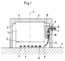
- Figure 1 shows the electrodynamic ultrasonic transducer in a sectional view.
- the housing 2 made of soft iron has a recess 11 or lateral holding projections where the permanent magnet 3 abuts.
- the dimensions of this recess 11 or these projections are designed such that an air gap is present between the side surfaces of the magnet 3 and the projections 11 at room temperature. This ensures that even with the present materials, despite different expansion coefficients, there is no mechanical stress at higher temperatures.
- the dimensions of the depth of the recess 11 or the projections are, however, such that a desired position of the permanent magnet 3 within the housing 2 is nevertheless given.
- the coaxial cable 7 is passed laterally through a bore 8 in the housing 2 and glued to the outside of the housing in a watertight manner.
- the signal line 12 of the coaxial cable 7 extends into the interior of the housing 2 and forms the electrical contact via a brazed connection and a wire loop 9 the converter wires.
- the brazing point is generously insulated and cast with a block 13 made of PEEKK.
- the block 13 is firmly glued to the housing inner wall near the entry point of the coaxial cable into the housing 2.
- one of the loose converter wire ends 9 is led, for example as a loop, to the brazing point.
- This wire 9, like the wires of the converter coil 5, is insulated with PEEKK.
- the carrier 6 for the transducer coil 5 is designed and arranged such that it bears against the permanent magnet 3 over a smooth, flat surface in the position shown and has the comb-like toothing on the side facing the workpiece surface 1, in which the transducer wires 5 are arranged.
- the carrier 6 consists of Corovac OF.
- the magnetic field lines are introduced into the workpiece surface 1 by the permanent magnet 3 via the carrier 6, the soft iron housing 2 then bringing about the necessary magnetic inference of the field lines. All individual magnetic parts, ie housing 2, permanent magnet 3 and Corovac carrier 6 are held together exclusively by magnetic forces.
- the entire ultrasonic transducer is free of mechanical stresses and thus also free of possible operational disturbances, even with different thermal expansion coefficients in a temperature range up to 300 degrees Celsius .
- the Sm2CO17 permanent magnet material used has the specific property of maintaining high remanence even in the temperature range mentioned.
- the use of the PEEKK insulation material ensures the splash water and radiation resistance even at higher temperatures, ie up to 320 degrees Celsius.
- Figure 2 shows a detailed drawing of the carrier.
- the side view poses the carrier 6 similar to that shown in Figure 1.
- the carrier 6 is designed so that a comb-like toothing is also formed in the plan view along the line AA in the edge region of the longitudinal sides 14.
- An embodiment of this type is only relevant when using non-magnetic materials, such as. B. ceramic or PEEKK.
- Corovac a configuration of the carrier, as shown in the top view, would not be suitable, because strongly inhomogeneous magnetic field line profiles would occur on the additional comb-like teeth.
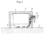
- FIG. 3 shows an electrodynamic ultrasound transducer for the special application of vertical insonification.
- the transmitting and receiving coils are wound on a common carrier 6 made of Corovac.
- the coaxial cable 7 is in this case multi-core, i. H. here provided with two signal lines 12, 12 '.
- the resulting soldered connections are embedded in a common insulation block 13 made of PEEKK and, as shown in FIG. 1, connected to the inner wall of the housing.
- the carrier 6, which in this case consists of Corovac OF, is designed in the shape of a truncated cone and is oriented such that the truncated cone tapers towards the workpiece surface 1.
- the concentrator effect thus achieved improves the efficiency of the ultrasound generation.
- the common arrangement of the transmitting and receiving transducer coil in a common ultrasonic transducer is not mandatory, i. H. Transmitter and receiver transducer coils can also be accommodated in various ultrasonic transducers.
Landscapes
- Physics & Mathematics (AREA)
- Electromagnetism (AREA)
- Engineering & Computer Science (AREA)
- Mechanical Engineering (AREA)
- Investigating Or Analyzing Materials By The Use Of Ultrasonic Waves (AREA)
- Length Measuring Devices Characterised By Use Of Acoustic Means (AREA)
Applications Claiming Priority (2)
| Application Number | Priority Date | Filing Date | Title |
|---|---|---|---|
| DE4016741A DE4016741C1 (enExample) | 1990-05-21 | 1990-05-21 | |
| DE4016741 | 1990-05-21 |
Publications (3)
| Publication Number | Publication Date |
|---|---|
| EP0458426A2 EP0458426A2 (de) | 1991-11-27 |
| EP0458426A3 EP0458426A3 (en) | 1993-02-24 |
| EP0458426B1 true EP0458426B1 (de) | 1995-02-01 |
Family
ID=6407099
Family Applications (1)
| Application Number | Title | Priority Date | Filing Date |
|---|---|---|---|
| EP91250095A Revoked EP0458426B1 (de) | 1990-05-21 | 1991-04-09 | Elektrodynamischer Ultraschallwandler und Ultraschalleinrichtung |
Country Status (2)
| Country | Link |
|---|---|
| EP (1) | EP0458426B1 (enExample) |
| DE (2) | DE4016741C1 (enExample) |
Cited By (1)
| Publication number | Priority date | Publication date | Assignee | Title |
|---|---|---|---|---|
| WO2021081307A1 (en) * | 2019-10-25 | 2021-04-29 | Molex, Llc | Ultrasonic patch transducer for monitoring the condition of a structural asset |
Family Cites Families (4)
| Publication number | Priority date | Publication date | Assignee | Title |
|---|---|---|---|---|
| US3963980A (en) * | 1973-08-29 | 1976-06-15 | Jury Mikhailovich Shkarlet | Ultrasonic instrument for non-destructive testing of articles with current-conducting surface |
| CA1063710A (en) * | 1976-08-31 | 1979-10-02 | Erazm A. Willy | Electromagnetic transducer |
| DE2655804C3 (de) * | 1976-12-09 | 1980-01-24 | Fraunhofer-Gesellschaft Zur Foerderung Der Angewandten Forschung E.V., 8000 Muenchen | Elektrodynamischer Ultraschallwellenwandler |
| US4058002A (en) * | 1976-12-23 | 1977-11-15 | The United States Of America As Represented By The Secretary Of The Air Force | Dispersive electromagnetic surface acoustic wave transducer |
-
1990
- 1990-05-21 DE DE4016741A patent/DE4016741C1/de not_active Expired - Fee Related
-
1991
- 1991-04-09 EP EP91250095A patent/EP0458426B1/de not_active Revoked
- 1991-04-09 DE DE59104457T patent/DE59104457D1/de not_active Revoked
Cited By (2)
| Publication number | Priority date | Publication date | Assignee | Title |
|---|---|---|---|---|
| WO2021081307A1 (en) * | 2019-10-25 | 2021-04-29 | Molex, Llc | Ultrasonic patch transducer for monitoring the condition of a structural asset |
| US12449404B2 (en) | 2019-10-25 | 2025-10-21 | Molex, Llc | Ultrasonic patch transducer for monitoring the condition of a structural asset |
Also Published As
| Publication number | Publication date |
|---|---|
| DE4016741C1 (enExample) | 1991-06-20 |
| EP0458426A2 (de) | 1991-11-27 |
| EP0458426A3 (en) | 1993-02-24 |
| DE59104457D1 (de) | 1995-03-16 |
Similar Documents
| Publication | Publication Date | Title |
|---|---|---|
| DE68915241T2 (de) | Nach dem Coriolis-Prinzip arbeitender Hochtemperatur-Massendurchflussmesser. | |
| DE3834248C2 (enExample) | ||
| DE102004023815A1 (de) | Antennenanordnung und Verwendung der Antennenanordnung | |
| DE2162196B2 (de) | Wellentypwandler | |
| DE69634988T2 (de) | Akustische wandlerkomponenten | |
| EP0458425A2 (de) | Elektrodynamischer Permanentmagnetwandler | |
| EP2936514A1 (de) | Induktivladespulenvorrichtung | |
| EP1299197B1 (de) | Elektromagnetischer ultraschallwandler | |
| DE202013103566U1 (de) | Optischer Resonanzscanner | |
| EP1538424A1 (de) | Mikrowellenwegmesssystem für elektrodynamischen Direktantrieb | |
| EP1658668B1 (de) | Anordnung zur berührungslosen induktiven übertragung elektrischer leistung | |
| DE4124103C1 (enExample) | ||
| DE3685859T2 (de) | Vibrationsempfindlicher transduktor. | |
| EP0787975A1 (de) | Magnetisch-induktiver Durchflussmesser | |
| EP0458426B1 (de) | Elektrodynamischer Ultraschallwandler und Ultraschalleinrichtung | |
| DE102006053023B4 (de) | Induktiver Näherungsschalter | |
| DE3637366C2 (enExample) | ||
| EP0069865B1 (de) | Elektrodynamischer Wandlerkopf | |
| DE10133171C1 (de) | Verfahren und Einrichtung zur Positionserfassung | |
| DE60002324T2 (de) | Schutzvorrichtung gegen elektromagnetische strahlung mit dichtungen | |
| DE112005000106T5 (de) | Elektromagnetisch-Akustischer Messwandler | |
| DE2944819C2 (enExample) | ||
| DE2038687A1 (de) | Akustischer Wandler | |
| DE102011111849A1 (de) | Linearbewegungsvorrichtung mit an einem Bimetallabschnitt befestigter Abtastvorrichtung einer Wegmesseinrichtung | |
| DE3042645C2 (de) | Elektrodynamischer zumindest je eine Erreger- u. eine Empfangsspule umfassender Ultraschallwandler |
Legal Events
| Date | Code | Title | Description |
|---|---|---|---|
| PUAI | Public reference made under article 153(3) epc to a published international application that has entered the european phase |
Free format text: ORIGINAL CODE: 0009012 |
|
| AK | Designated contracting states |
Kind code of ref document: A2 Designated state(s): DE FR IT |
|
| PUAL | Search report despatched |
Free format text: ORIGINAL CODE: 0009013 |
|
| AK | Designated contracting states |
Kind code of ref document: A3 Designated state(s): DE FR IT |
|
| 17P | Request for examination filed |
Effective date: 19930323 |
|
| 17Q | First examination report despatched |
Effective date: 19940322 |
|
| GRAA | (expected) grant |
Free format text: ORIGINAL CODE: 0009210 |
|
| AK | Designated contracting states |
Kind code of ref document: B1 Designated state(s): DE FR IT |
|
| ITF | It: translation for a ep patent filed | ||
| ET | Fr: translation filed | ||
| REF | Corresponds to: |
Ref document number: 59104457 Country of ref document: DE Date of ref document: 19950316 |
|
| PGFP | Annual fee paid to national office [announced via postgrant information from national office to epo] |
Ref country code: FR Payment date: 19950320 Year of fee payment: 5 |
|
| PLBI | Opposition filed |
Free format text: ORIGINAL CODE: 0009260 |
|
| 26 | Opposition filed |
Opponent name: SIEMENS AG Effective date: 19951031 |
|
| PGFP | Annual fee paid to national office [announced via postgrant information from national office to epo] |
Ref country code: DE Payment date: 19960521 Year of fee payment: 6 |
|
| PLBF | Reply of patent proprietor to notice(s) of opposition |
Free format text: ORIGINAL CODE: EPIDOS OBSO |
|
| RDAG | Patent revoked |
Free format text: ORIGINAL CODE: 0009271 |
|
| STAA | Information on the status of an ep patent application or granted ep patent |
Free format text: STATUS: PATENT REVOKED |
|
| 27W | Patent revoked |
Effective date: 19960627 |