EP0457427B1 - Gerät zur Verbesserung der Schärfe bei einem Farbbild - Google Patents
Gerät zur Verbesserung der Schärfe bei einem Farbbild Download PDFInfo
- Publication number
- EP0457427B1 EP0457427B1 EP91302943A EP91302943A EP0457427B1 EP 0457427 B1 EP0457427 B1 EP 0457427B1 EP 91302943 A EP91302943 A EP 91302943A EP 91302943 A EP91302943 A EP 91302943A EP 0457427 B1 EP0457427 B1 EP 0457427B1
- Authority
- EP
- European Patent Office
- Prior art keywords
- color
- signals
- sharpening
- collection
- color separation
- Prior art date
- Legal status (The legal status is an assumption and is not a legal conclusion. Google has not performed a legal analysis and makes no representation as to the accuracy of the status listed.)
- Expired - Lifetime
Links
Images


Classifications
-
- H—ELECTRICITY
- H04—ELECTRIC COMMUNICATION TECHNIQUE
- H04N—PICTORIAL COMMUNICATION, e.g. TELEVISION
- H04N1/00—Scanning, transmission or reproduction of documents or the like, e.g. facsimile transmission; Details thereof
- H04N1/46—Colour picture communication systems
- H04N1/56—Processing of colour picture signals
- H04N1/58—Edge or detail enhancement; Noise or error suppression, e.g. colour misregistration correction
Definitions
- the present invention relates to detail enhancement of color images generally.
- Analog and digital detail enhancement known as "unsharp masking” is well known and widely used in the graphic arts, as well as in other fields. It is used to produce sharp printed reproductions from original images by enhancing the color density differences at edges between areas of different color and is discussed in the following publications: Jackson, Lonnie L., "Unsharp Masking: Photographic/Electronic," Gatfworld , May-June 1989, Vol. 1, pp. 13 - 22; Molla, R.K., Electronic Color Separation , R.K. Printing & Publishing Co., Montgomery, W. Virginia, 1988, pp. 230 - 232; and U.S.-A-4,335,407 to Atoji et al.
- Two methods are used for detail enhancement, the utilization of a single color channel to produce a single detail enhancement signal for each of three or four color channels or for each of the three or four printers and the utilization of each color channel to produce a separate detail enhancement signal per channel. These two methods can be implemented in both analog and digital systems, such as color separation scanners.
- the first method adds to the enhanced edges a generally gray line, making the edge of a color area appear to be more gray. This effect, often referred to as “contours", is undesirable for most graphic arts applications.
- the second method adds a color enhancing line to the edge of a color area, thereby generally enhancing the color separation of the area at the edge to more sharply define the color edge. This effect is desirable and produces printed images of high quality.
- the two methods have their advantages and disadvantages, particularly in regard to color noise.
- color noise When scanning a color area, many pixels are produced to represent the area and the average color of the pixels in the area is the color of the area.
- an individual pixel will typically have a color which is slightly different from the average color of the area. This effect is known as color noise and is easily detected by the human eye, especially when the average color is gray.
- the second method emphasizes this effect by adding a color component to each pixel.
- the first method adds a gray component to each pixel, thereby reducing the color separation in the pixel and consequently, reducing the color noise.
- both methods provide a sharpening line of the same average color and are, therefore, equivalent.
- the second method will increase any color noise in the gray areas and the first method will reduce it.
- an object of the present invention to provide an apparatus and method for sharpening a color image which utilizes more than one method of detail enhancement for reproduction of any original image.
- an apparatus for sharpening a color image having a multiplicity of color separation signals defining a plurality of color pixels comprising apparatus for generating at least two sharpening signals from the color separation signals and apparatus for combining each of the color separation signals with any collection of the at least two sharpening signals, a collection consisting of none, one, or any combination of said at least two sharpening signals, and wherein the collection changes throughout the color image.
- the apparatus for combining includes apparatus for determining the collection as a function of at least one dimension of the at least three dimensional color value of each of the plurality of pixels.
- the apparatus for determining includes apparatus for separating a color solid into first, second and third volumes. If the three dimensional color value of a pixel falls within the first volume, a first collection of sharpening signals are combined with the color separation signals. If the three dimensional color value of a pixel falls within the third volume a second collection of sharpening signals are combined with the color separation signals. If the three dimensional color value of a pixel falls within the second volume, located generally between the first and third volumes, a combination of the first and the second collections of sharpening signals are combined with the color separation signals wherein the combination gradually changes from generally the entirety of the first collection to generally the entirety of the second collection.
- the apparatus for generating includes apparatus for performing edge detection on each of the color separation signals.
- the color separation signals are in a predetermined color space and the sharpening signals are also in the predetermined color space.
- a method of sharpening a color image having a multiplicity of color separation signals defining a plurality of color pixels including the steps of generating at least two sharpening signals from the color separation signals and combining each of the color separation signals with any collection of the at least two sharpening signals, a collection consisting of none, one, or any combination of said at least two sharpening signals, and wherein the collection changes throughout the color image.
- the step of combining includes the step of determining the collection as a function of at least one dimension of the at least three dimensional color value of each of the plurality of pixels.
- the step of determining includes the step of separating a color solid into first, second and third volumes. If the three dimensional color value of a pixel falls within the first volume, a first collection of sharpening signals are combined with the color separation signals. If the three dimensional color value of a pixel falls within the third volume a second collection of sharpening signals are combined with the color separation signals. If the three dimensional color value of a pixel falls within the second volume, located generally between the first and third volumes, a combination of the first and the second collections of sharpening signals are combined with the color separation signals wherein the combination gradually changes from generally the entirety of the first collection to generally the entirety of the second collection.
- the step of generating includes the step of performing edge detection on each of the color separation signals.
- Fig. 1 illustrates, in block diagram form, the system for color sharpening of the present invention.
- the system comprises a sharp signal generator 10 for receiving Red (R), Green (G) and Blue (B) color separation signals from a color separation source, such as a color separation scanner or a color separation camera, and for producing sharp signals R e , G e , and B e , respectively, for the Red, Green and Blue color separation signals.
- the color separation signals can be of the Cyan (C), Magenta (M), Yellow (Y) and Black (K) separation, or of any other suitable color separation.
- the sharp signal generator 10 produces the sharp signals C e , M e , Y e , and H e . It will be appreciated that the sharp signals are preferably in the same color space as the input color separation signals where, for the following description, the Red, Green and Blue color space will be used.
- the system additionally comprises three summers 12, 14 and 16 for receiving a color separation signal from a color separation source, and any or none of sharp signals R e , G e or B e .
- the color separation signals received by summers 12, 14 and 16 are respectively, the Red (R), Green (G) and Blue (B) color separation signals.
- the sharp signals R e , G e and B e are received by summers 12, 14 and 16, via three individually controlled switches 20, 22 and 24, respectively, operative to switch the signals between three positions, A, 0 and S.
- the first method described in the Background of the Invention is the mode wherein one of the switches, typically switch 22 which receives G e , is set to the A position and the remaining switches 20 and 24 are set to the 0 position.
- the second method described in the Background of the Invention is the mode wherein each of the switches 20, 22 and 24 is set to the S position.
- the switches 20, 22 and 24 are individually operated by a color coordinates computer 30 in accordance with a predefined color criteria.
- the color criteria define ranges within a three-dimensional color space in which a given mode will be operative.
- the color coordinates computer 30 receives the R, G and B color separation signals and, for each pixel, determines where in the three-dimensional color space a given pixel lies. The switch setting for the range within which the given pixel lies will then be implemented.
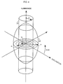
- a typical three-dimensional color space known as the Munsell Color Solid, is shown in Fig. 3 and marked as reference number 30. It is described on pages 507 - 510 of the book, Color Science: Concepts and Methods, Quantitative Data and Formulae , 2nd Edition, by Gunter Wyszecki and W.S. Stiles and published by John Wiley and Sons, New York, NY in 1982.
- the vertical axis is the luminance axis
- the horizontal plane comprises the polar axes of saturation and hue where saturation is the radial component and hue is the angular component.
- a typical, two range color criteria can be defined by intersecting the Munsell Color Solid 30 with a cylinder 32 of radius r o along the luminance axis. All pixels falling within the intersection of the Solid 30 and the cylinder 32 are relatively gray pixels for which the first method of the Background of the Invention is operative. All pixels not falling within the intersection of the Solid 30 and the cylinder 32 are non-gray pixels for which the second method of the Background of the Invention is operative.
- a second, two range color criteria can be defined by defining a volume with luminance higher than a first threshold and lower than a second threshold.
- criteria utilizing the Munsell Color Solid 30 require a transformation of the R, G and B color components of each pixel to luminance, hue and saturation components. Other criteria may be defined which are expressed in the R, G and B color coordinates. If more than two color criteria ranges are required, the three-dimensional color solid is divided into smaller, non-overlapping range volumes.
- the sharp signal generator 10 separately performs edge detection and edge signal generation from each of the color separation signals R, G and B. To each detected edge in each of the color separations, it increases the brightness content of the bright side of the edge and decreases the content of the darker side of the edge. Generally, the steeper the edge, the greater the increase and decrease in the color content of the two sides of the edge.
- the present invention minimally requires the generation of two sharp signals.
- the red and green sharp signals, R e and G e are generated and one of them is additionally input to switch 24.
- the sharp signal generator 10 can generate four sharp signals.
- Fig. 2 illustrates a further embodiment of the present invention.
- the switches 20, 22 and 24 are replaced by edge selectors 40, 42 and 44, respectively.
- the color coordinates computer 30 indicates to each edge selector 40, 42 and 44 which sharp signal R e , G e or B e to select, thereby allowing for 27 different modes of connecting the sharp signals to the channels.
- the collection of sharp signals to be connected to the channels can include all of one sharp signal or one of each signal or some other collection.
- the area with radii of less than r o typically defines a first mode and the area with radii between r o and r1 defines a second mode.
- the first mode might be that all color separation signals R, G and B receive the sharp signal G e .
- the second mode might be that each color separation R, G or B receives its corresponding sharp signal, R e , G e or B e .
- the first mode is operative. If the radius r falls within the area of the Solid 30 between r b and r1, the second mode is operative. If the radius r falls within the area of the Solid 30 between r a and r b , the color separations R, G and B receive a first percentage of the sharp signals R e , G e and B e they receive in the first mode and a second percentage of the sharp signals they receive in the second mode, where the first percentage is defined by how close the radius r is to r a and the second percentage is defined by how close the radius is to r b . The sum of the first and second percentages is equal to 1.
- R ⁇ R e *(a/c) + G e *(b/c)
- G ⁇ G e *(a/c) + G e *(b/c)
- B ⁇ B e *(a/c) + G e *(b/c)
- a (r - r a )
- b (r b - r)
- c (r b - r a )
- the sharp signals received resemble the sharp signals received in the second mode.
- the sharp signals received resemble the sharp signals received in the first mode.
Claims (9)
- Vorrichtung zur Schärfverbesserung eines Farbbildes mit mehreren Farbseparationssignalen, welche mehrere Farbbildpunkte bilden, mit:
einer Einrichtung zum Erzeugen von wenigstens zwei Schärfverbesserungssignalen aus den Farbseparationssignalen; und
einer Einrichtung zum Kombinieren jedes der Farbseparationssignale mit jeder Zusammenstellung von wenigstens zwei Schärfverbesserungssignalen, wobei eine Zusammenstellung aus keiner, einer oder einer Kombination der wenigstens zwei Schärfverbesserungssignale besteht, wobei die Zusammenstellung im Verlauf des Farbbildes wechselt. - Vorrichtung nach Anspruch 1, bei welcher die Einrichtung zum Kombinieren eine Einrichtung zum Bestimmen der Zusammenstellung als Funktion von wenigstens einer Dimension des wenigstens dreidimensionalen Farbwertes von jedem der Bildpunkte beinhaltet.
- Vorrichtung nach Anspruch 2, bei welcher die Bestimmungseinrichtung eine Einrichtung zum Separieren eines Farbkörpers in erste, zweite und dritte Mengen beinhaltet, wobei, wenn der dreidimensionale Farbwert eines Bildpunktes in die erste Menge fällt, eine erste Zusammenstellung von schärfeverbessernden Signalen mit den Farbseparationssignalen kombiniert wird, wenn der dreidimensionale Farbwert eines Bildpunktes in die dritte Menge fällt, eine zweite Zusammenstellung von schärfeverbessernden Signalen mit den Farbseparationssignalen kombiniert wird, und wenn der dreidimensionale Farbwert eines Bildpunktes in die zweite Menge fällt, welche allgemein zwischen der ersten und der dritten Menge angeordnet ist, eine Kombination der ersten und der zweiten Zusammenstellung der schärfeverbessernden Signale mit den Farbseparationssignalen kombiniert wird, wobei sich die Kombination allmählich von im wesentlichen der Gesamtheit der ersten Zusammenstellung zu im wesentlichen der Gesamtheit der zweiten Zusammenstellung ändert.
- Vorrichtung nach einem der vorstehenden Ansprüche, bei welchem die Erzeugungseinrichtung eine Einrichtung zum Ausführen einer Flankenerkennung von jedem der Farbseparationssignale beinhaltet.
- Vorrichtung nach einem der vorstehenden Ansprüche, bei welcher sich die Farbseparationssignale in einem vorbestimmten Farbraum befinden und sich die schärfeverbessernden Signale ebenfalls in dem vorbestimmten Farbraum befinden.
- Verfahren zur Schärfeverbesserung eines Farbbildes mit mehreren Farbseparationssignalen, welche eine Mehrzahl von Farbbildpunkten bilden, mit den Schritten:
Erzeugen wenigstens zweier schärfeverbessernder Signale aus den Farbseparationssignalen; und
Kombinieren jedes der Farbseparationssignale mit einer Zusammenstellung von wenigstens zwei schärfeverbessernden Signalen, wobei eine Zusammenstellung aus keiner, einer oder einer Kombination der wenigstens zwei schärfeverbessernden Signale besteht, wobei die Zusammenstellung sich im Verlauf des Farbbildes ändert. - Verfahren nach Anspruch 6, bei welchem der Schritt des Kombinierens den Schritt des Bestimmens der Zusammenstellung als Funktion von wenigstens einer Dimension des wenigstens dreidimensionalen Farbwertes von jedem der Bildpunkte beinhaltet.
- Verfahren nach Anspruch 7, bei welchem der Bestimmungsschritt den Schritt des Separierens eines Farbkörpers in erste, zweite und dritte Mengen beinhaltet, wobei, wenn der dreidimensionale Farbwert eines Bildpunktes in die erste Menge fällt, eine erste Zusammenstellung von schärfeverbessernden Signalen mit den Farbseparationssignalen kombiniert wird, wenn der dreidimensionale Farbwert eines Bildpunktes in die dritte Menge fällt, eine zweite Zusammenstellung von schärfeverbessernden Signalen mit den farbseparierenden Signalen kombiniert wird, und wenn der dreidimensionale Farbwert eines Bildpunktes in die zweite Menge fällt, die allgemein zwischen der ersten und der dritten Menge angeordnet ist, eine Kombination der ersten und der zweiten Zusammenstellung von schärfeverbessernden Signalen mit den Farbseparationssignalen kombiniert wird, wobei die Kombination sich allmählich von im wesentlichen der Gesamtheit der ersten Zusammenstellung zu im wesentlichen der Gesamtheit der zweiten Zusammenstellung ändert.
- Verfahren nach einem der Ansprüche 6 bis 7, wobei der Erzeugungsschritt den Schritt des Ausführens der Flankenerkennung von jedem der Farbseparationssignale beinhaltet.
Applications Claiming Priority (4)
| Application Number | Priority Date | Filing Date | Title |
|---|---|---|---|
| IL94215 | 1990-04-26 | ||
| IL94215A IL94215A0 (en) | 1990-04-26 | 1990-04-26 | Apparatus for sharpening a color image |
| IL9495690A IL94956A (en) | 1990-07-03 | 1990-07-03 | Facility to sharpen a colorful figure |
| IL94956 | 1990-07-03 |
Publications (3)
| Publication Number | Publication Date |
|---|---|
| EP0457427A2 EP0457427A2 (de) | 1991-11-21 |
| EP0457427A3 EP0457427A3 (en) | 1993-02-10 |
| EP0457427B1 true EP0457427B1 (de) | 1995-12-06 |
Family
ID=26322080
Family Applications (1)
| Application Number | Title | Priority Date | Filing Date |
|---|---|---|---|
| EP91302943A Expired - Lifetime EP0457427B1 (de) | 1990-04-26 | 1991-04-04 | Gerät zur Verbesserung der Schärfe bei einem Farbbild |
Country Status (6)
| Country | Link |
|---|---|
| US (1) | US5247352A (de) |
| EP (1) | EP0457427B1 (de) |
| JP (1) | JPH04229766A (de) |
| AT (1) | ATE131328T1 (de) |
| CA (1) | CA2040937A1 (de) |
| DE (1) | DE69115117T2 (de) |
Cited By (4)
| Publication number | Priority date | Publication date | Assignee | Title |
|---|---|---|---|---|
| EP0525949A2 (de) * | 1991-07-30 | 1993-02-03 | Polaroid Corporation | Numerische Bildverarbeitungsschaltung |
| EP0566915A1 (de) * | 1992-04-21 | 1993-10-27 | Dainippon Screen Mfg. Co., Ltd. | Bildschärfenverarbeitungsgerät |
| US5751845A (en) * | 1993-04-08 | 1998-05-12 | Linotype Hell Ag | Method for generating smooth color corrections in a color space, particularly a CIELAB color space |
| US5793501A (en) * | 1995-03-16 | 1998-08-11 | Dainippon Screen Mfg. Co., Ltd. | Contrast correcting apparatus |
Families Citing this family (14)
| Publication number | Priority date | Publication date | Assignee | Title |
|---|---|---|---|---|
| JP2852390B2 (ja) * | 1991-02-16 | 1999-02-03 | 株式会社半導体エネルギー研究所 | 表示装置 |
| US5384862A (en) * | 1992-05-29 | 1995-01-24 | Cimpiter Corporation | Radiographic image evaluation apparatus and method |
| DE4225508C2 (de) * | 1992-08-01 | 1994-07-28 | Hell Ag Linotype | Verfahren und Schaltungsanordnung zur Kontraststeigerung |
| US5383036A (en) * | 1993-09-29 | 1995-01-17 | Xerox Corporation | Enhancement of multiple color images without color separation error by inverse symmetrical template matching |
| US5363209A (en) * | 1993-11-05 | 1994-11-08 | Xerox Corporation | Image-dependent sharpness enhancement |
| US5581370A (en) * | 1995-06-05 | 1996-12-03 | Xerox Corporation | Image-dependent automatic area of interest enhancement |
| JP3356201B2 (ja) * | 1996-04-12 | 2002-12-16 | ソニー株式会社 | ビデオカメラおよび輪郭強調装置 |
| DE19722761B4 (de) * | 1997-06-02 | 2006-06-01 | Hell Gravure Systems Gmbh | Verfahren zur Aufbereitung von Bilddaten |
| US6563601B1 (en) * | 1997-07-28 | 2003-05-13 | Canon Business Machines, Inc. | System for printing image data divided at a break point |
| JPH11305743A (ja) | 1998-04-23 | 1999-11-05 | Semiconductor Energy Lab Co Ltd | 液晶表示装置 |
| US6224189B1 (en) * | 1999-08-26 | 2001-05-01 | Xerox Corporation | Enhanced text and line-art quality for multi-resolution marking devices |
| FI115942B (fi) | 2002-10-14 | 2005-08-15 | Nokia Corp | Menetelmä kuvien interpoloimiseksi ja terävöittämiseksi |
| JP4245019B2 (ja) * | 2006-09-04 | 2009-03-25 | ソニー株式会社 | ビューファインダ、撮像装置および表示信号生成回路 |
| US20080229370A1 (en) * | 2007-03-13 | 2008-09-18 | Zustak Frederick J | TV-centric system |
Family Cites Families (7)
| Publication number | Priority date | Publication date | Assignee | Title |
|---|---|---|---|---|
| JPS55146451A (en) * | 1979-05-02 | 1980-11-14 | Dainippon Screen Mfg Co Ltd | Sharpness emphasis method in image scanning recorder |
| EP0098319B1 (de) * | 1982-07-03 | 1986-03-26 | DR.-ING. RUDOLF HELL GmbH | Verfahren und Anordnung zur Kontraststeigerung |
| US4734763A (en) * | 1983-07-04 | 1988-03-29 | Fuji Photo Film Co., Ltd. | Apparatus for generating positive or negative image output signals from either positive or negative originals |
| US4672431A (en) * | 1983-10-26 | 1987-06-09 | Harris Corporation | Contour correction system when one color signal is low |
| JPS60169274A (ja) * | 1984-02-10 | 1985-09-02 | Dainippon Screen Mfg Co Ltd | 画像走査記録装置に於ける輪郭強調信号処理方法 |
| JP2677283B2 (ja) * | 1984-06-14 | 1997-11-17 | キヤノン株式会社 | カラー画像処理装置 |
| EP0327107B1 (de) * | 1988-02-05 | 1994-07-13 | Dainippon Screen Mfg. Co., Ltd. | Bildschärfeverbesserungsverfahren und -prozessor für Bildreproduktion mit Abtaster |
-
1991
- 1991-04-04 DE DE69115117T patent/DE69115117T2/de not_active Expired - Fee Related
- 1991-04-04 EP EP91302943A patent/EP0457427B1/de not_active Expired - Lifetime
- 1991-04-04 AT AT91302943T patent/ATE131328T1/de not_active IP Right Cessation
- 1991-04-10 US US07/683,268 patent/US5247352A/en not_active Expired - Fee Related
- 1991-04-22 CA CA002040937A patent/CA2040937A1/en not_active Abandoned
- 1991-04-26 JP JP3097432A patent/JPH04229766A/ja active Pending
Cited By (5)
| Publication number | Priority date | Publication date | Assignee | Title |
|---|---|---|---|---|
| EP0525949A2 (de) * | 1991-07-30 | 1993-02-03 | Polaroid Corporation | Numerische Bildverarbeitungsschaltung |
| EP0566915A1 (de) * | 1992-04-21 | 1993-10-27 | Dainippon Screen Mfg. Co., Ltd. | Bildschärfenverarbeitungsgerät |
| US5442717A (en) * | 1992-04-21 | 1995-08-15 | Dainippon Screen Mfg. Co., Ltd. | Sharpness processing apparatus |
| US5751845A (en) * | 1993-04-08 | 1998-05-12 | Linotype Hell Ag | Method for generating smooth color corrections in a color space, particularly a CIELAB color space |
| US5793501A (en) * | 1995-03-16 | 1998-08-11 | Dainippon Screen Mfg. Co., Ltd. | Contrast correcting apparatus |
Also Published As
| Publication number | Publication date |
|---|---|
| DE69115117D1 (de) | 1996-01-18 |
| ATE131328T1 (de) | 1995-12-15 |
| CA2040937A1 (en) | 1991-10-27 |
| DE69115117T2 (de) | 1996-05-09 |
| EP0457427A2 (de) | 1991-11-21 |
| US5247352A (en) | 1993-09-21 |
| EP0457427A3 (en) | 1993-02-10 |
| JPH04229766A (ja) | 1992-08-19 |
Similar Documents
| Publication | Publication Date | Title |
|---|---|---|
| EP0457427B1 (de) | Gerät zur Verbesserung der Schärfe bei einem Farbbild | |
| US5146346A (en) | Method for displaying and printing multitone images derived from grayscale images | |
| EP0411911B1 (de) | Bildverarbeitungsgerät | |
| US5729360A (en) | Color image processing method and system | |
| EP0491556B1 (de) | Bildverarbeitungsverfahren und -gerät | |
| US5420938A (en) | Image processing apparatus | |
| JPH0998298A (ja) | 色域圧縮方法及び色域圧縮装置 | |
| JP2001144989A (ja) | 画像処理装置、方法、記録媒体およびコンピュータプログラム | |
| US6744921B1 (en) | Image processing apparatus and method that determines the thickness of characters and lines | |
| US6181819B1 (en) | Image processing apparatus including means for judging a chromatic portion of an image | |
| US6665435B1 (en) | Image data processing method and corresponding device | |
| JP2906974B2 (ja) | カラー画像処理方法および装置 | |
| EP0612182B1 (de) | Bildelement- und Datenformatumwandlungsprozessor für Tiefdruck | |
| JP3452212B2 (ja) | 減色処理を行なうカラー画像処理装置 | |
| JP2807473B2 (ja) | カラー画像のエッジ部検出方法 | |
| JP2002218271A (ja) | 画像処理装置、画像形成装置、並びに画像処理方法 | |
| IL94956A (en) | Facility to sharpen a colorful figure | |
| JP3093217B2 (ja) | 画像処理装置及び画像処理方法 | |
| JP2002094826A (ja) | 画像処理装置、画像形成装置、並びに画像処理方法 | |
| JP2951972B2 (ja) | 画像処理装置 | |
| JP2803852B2 (ja) | 画像処理装置 | |
| JP2941853B2 (ja) | 画像処理方法 | |
| JP2947823B2 (ja) | 画像処理装置 | |
| JP3126358B2 (ja) | 画像処理方法 | |
| JP2941852B2 (ja) | 画像処理方法 |
Legal Events
| Date | Code | Title | Description |
|---|---|---|---|
| PUAI | Public reference made under article 153(3) epc to a published international application that has entered the european phase |
Free format text: ORIGINAL CODE: 0009012 |
|
| AK | Designated contracting states |
Kind code of ref document: A2 Designated state(s): AT BE CH DE DK ES FR GB GR IT LI LU NL SE |
|
| PUAL | Search report despatched |
Free format text: ORIGINAL CODE: 0009013 |
|
| 17P | Request for examination filed |
Effective date: 19921028 |
|
| AK | Designated contracting states |
Kind code of ref document: A3 Designated state(s): AT BE CH DE DK ES FR GB GR IT LI LU NL SE |
|
| 17Q | First examination report despatched |
Effective date: 19950411 |
|
| GRAA | (expected) grant |
Free format text: ORIGINAL CODE: 0009210 |
|
| AK | Designated contracting states |
Kind code of ref document: B1 Designated state(s): AT BE CH DE DK ES FR GB GR IT LI LU NL SE |
|
| PG25 | Lapsed in a contracting state [announced via postgrant information from national office to epo] |
Ref country code: IT Free format text: LAPSE BECAUSE OF FAILURE TO SUBMIT A TRANSLATION OF THE DESCRIPTION OR TO PAY THE FEE WITHIN THE PRE;WARNING: LAPSES OF ITALIAN PATENTS WITH EFFECTIVE DATE BEFORE 2007 MAY HAVE OCCURRED AT ANY TIME BEFORE 2007. THE CORRECT EFFECTIVE DATE MAY BE DIFFERENT FROM THE ONE RECORDED.SCRIBED TIME-LIMIT Effective date: 19951206 Ref country code: AT Effective date: 19951206 Ref country code: GR Free format text: LAPSE BECAUSE OF FAILURE TO SUBMIT A TRANSLATION OF THE DESCRIPTION OR TO PAY THE FEE WITHIN THE PRESCRIBED TIME-LIMIT Effective date: 19951206 Ref country code: LI Effective date: 19951206 Ref country code: NL Free format text: LAPSE BECAUSE OF FAILURE TO SUBMIT A TRANSLATION OF THE DESCRIPTION OR TO PAY THE FEE WITHIN THE PRESCRIBED TIME-LIMIT Effective date: 19951206 Ref country code: CH Effective date: 19951206 Ref country code: ES Free format text: THE PATENT HAS BEEN ANNULLED BY A DECISION OF A NATIONAL AUTHORITY Effective date: 19951206 Ref country code: DK Effective date: 19951206 |
|
| REF | Corresponds to: |
Ref document number: 131328 Country of ref document: AT Date of ref document: 19951215 Kind code of ref document: T |
|
| REF | Corresponds to: |
Ref document number: 69115117 Country of ref document: DE Date of ref document: 19960118 |
|
| PG25 | Lapsed in a contracting state [announced via postgrant information from national office to epo] |
Ref country code: SE Effective date: 19960306 |
|
| ET | Fr: translation filed | ||
| PG25 | Lapsed in a contracting state [announced via postgrant information from national office to epo] |
Ref country code: LU Free format text: LAPSE BECAUSE OF NON-PAYMENT OF DUE FEES Effective date: 19960430 |
|
| NLV1 | Nl: lapsed or annulled due to failure to fulfill the requirements of art. 29p and 29m of the patents act | ||
| REG | Reference to a national code |
Ref country code: CH Ref legal event code: PL |
|
| PLBE | No opposition filed within time limit |
Free format text: ORIGINAL CODE: 0009261 |
|
| STAA | Information on the status of an ep patent application or granted ep patent |
Free format text: STATUS: NO OPPOSITION FILED WITHIN TIME LIMIT |
|
| 26N | No opposition filed | ||
| PGFP | Annual fee paid to national office [announced via postgrant information from national office to epo] |
Ref country code: GB Payment date: 20000313 Year of fee payment: 10 |
|
| PGFP | Annual fee paid to national office [announced via postgrant information from national office to epo] |
Ref country code: DE Payment date: 20000320 Year of fee payment: 10 |
|
| PGFP | Annual fee paid to national office [announced via postgrant information from national office to epo] |
Ref country code: FR Payment date: 20000327 Year of fee payment: 10 |
|
| PGFP | Annual fee paid to national office [announced via postgrant information from national office to epo] |
Ref country code: BE Payment date: 20000405 Year of fee payment: 10 |
|
| PG25 | Lapsed in a contracting state [announced via postgrant information from national office to epo] |
Ref country code: GB Free format text: LAPSE BECAUSE OF NON-PAYMENT OF DUE FEES Effective date: 20010404 |
|
| PG25 | Lapsed in a contracting state [announced via postgrant information from national office to epo] |
Ref country code: BE Free format text: LAPSE BECAUSE OF NON-PAYMENT OF DUE FEES Effective date: 20010430 Ref country code: FR Free format text: THE PATENT HAS BEEN ANNULLED BY A DECISION OF A NATIONAL AUTHORITY Effective date: 20010430 |
|
| BERE | Be: lapsed |
Owner name: SCITEX CORP. LTD Effective date: 20010430 |
|
| GBPC | Gb: european patent ceased through non-payment of renewal fee |
Effective date: 20010404 |
|
| PG25 | Lapsed in a contracting state [announced via postgrant information from national office to epo] |
Ref country code: DE Free format text: LAPSE BECAUSE OF NON-PAYMENT OF DUE FEES Effective date: 20020201 |
|
| REG | Reference to a national code |
Ref country code: FR Ref legal event code: ST |