EP0457330B1 - Bilderzeugungsgerät - Google Patents
Bilderzeugungsgerät Download PDFInfo
- Publication number
- EP0457330B1 EP0457330B1 EP91107970A EP91107970A EP0457330B1 EP 0457330 B1 EP0457330 B1 EP 0457330B1 EP 91107970 A EP91107970 A EP 91107970A EP 91107970 A EP91107970 A EP 91107970A EP 0457330 B1 EP0457330 B1 EP 0457330B1
- Authority
- EP
- European Patent Office
- Prior art keywords
- image
- image forming
- drum
- forming apparatus
- light
- Prior art date
- Legal status (The legal status is an assumption and is not a legal conclusion. Google has not performed a legal analysis and makes no representation as to the accuracy of the status listed.)
- Expired - Lifetime
Links
Images


Classifications
-
- G—PHYSICS
- G03—PHOTOGRAPHY; CINEMATOGRAPHY; ANALOGOUS TECHNIQUES USING WAVES OTHER THAN OPTICAL WAVES; ELECTROGRAPHY; HOLOGRAPHY
- G03G—ELECTROGRAPHY; ELECTROPHOTOGRAPHY; MAGNETOGRAPHY
- G03G15/00—Apparatus for electrographic processes using a charge pattern
- G03G15/50—Machine control of apparatus for electrographic processes using a charge pattern, e.g. regulating differents parts of the machine, multimode copiers, microprocessor control
- G03G15/5008—Driving control for rotary photosensitive medium, e.g. speed control, stop position control
-
- B—PERFORMING OPERATIONS; TRANSPORTING
- B41—PRINTING; LINING MACHINES; TYPEWRITERS; STAMPS
- B41J—TYPEWRITERS; SELECTIVE PRINTING MECHANISMS, i.e. MECHANISMS PRINTING OTHERWISE THAN FROM A FORME; CORRECTION OF TYPOGRAPHICAL ERRORS
- B41J2/00—Typewriters or selective printing mechanisms characterised by the printing or marking process for which they are designed
- B41J2/435—Typewriters or selective printing mechanisms characterised by the printing or marking process for which they are designed characterised by selective application of radiation to a printing material or impression-transfer material
- B41J2/47—Typewriters or selective printing mechanisms characterised by the printing or marking process for which they are designed characterised by selective application of radiation to a printing material or impression-transfer material using the combination of scanning and modulation of light
- B41J2/471—Typewriters or selective printing mechanisms characterised by the printing or marking process for which they are designed characterised by selective application of radiation to a printing material or impression-transfer material using the combination of scanning and modulation of light using dot sequential main scanning by means of a light deflector, e.g. a rotating polygonal mirror
-
- G—PHYSICS
- G06—COMPUTING; CALCULATING OR COUNTING
- G06K—GRAPHICAL DATA READING; PRESENTATION OF DATA; RECORD CARRIERS; HANDLING RECORD CARRIERS
- G06K15/00—Arrangements for producing a permanent visual presentation of the output data, e.g. computer output printers
- G06K15/02—Arrangements for producing a permanent visual presentation of the output data, e.g. computer output printers using printers
- G06K15/12—Arrangements for producing a permanent visual presentation of the output data, e.g. computer output printers using printers by photographic printing, e.g. by laser printers
- G06K15/1204—Arrangements for producing a permanent visual presentation of the output data, e.g. computer output printers using printers by photographic printing, e.g. by laser printers involving the fast moving of an optical beam in the main scanning direction
- G06K15/1219—Detection, control or error compensation of scanning velocity or position, e.g. synchronisation
-
- G—PHYSICS
- G06—COMPUTING; CALCULATING OR COUNTING
- G06K—GRAPHICAL DATA READING; PRESENTATION OF DATA; RECORD CARRIERS; HANDLING RECORD CARRIERS
- G06K15/00—Arrangements for producing a permanent visual presentation of the output data, e.g. computer output printers
- G06K15/02—Arrangements for producing a permanent visual presentation of the output data, e.g. computer output printers using printers
- G06K15/16—Means for paper feeding or form feeding
-
- H—ELECTRICITY
- H04—ELECTRIC COMMUNICATION TECHNIQUE
- H04N—PICTORIAL COMMUNICATION, e.g. TELEVISION
- H04N1/00—Scanning, transmission or reproduction of documents or the like, e.g. facsimile transmission; Details thereof
- H04N1/00567—Handling of original or reproduction media, e.g. cutting, separating, stacking
- H04N1/0057—Conveying sheets before or after scanning
- H04N1/00588—Conveying sheets before or after scanning to the scanning position
-
- H—ELECTRICITY
- H04—ELECTRIC COMMUNICATION TECHNIQUE
- H04N—PICTORIAL COMMUNICATION, e.g. TELEVISION
- H04N1/00—Scanning, transmission or reproduction of documents or the like, e.g. facsimile transmission; Details thereof
- H04N1/00567—Handling of original or reproduction media, e.g. cutting, separating, stacking
- H04N1/0057—Conveying sheets before or after scanning
- H04N1/00591—Conveying sheets before or after scanning from the scanning position
-
- H—ELECTRICITY
- H04—ELECTRIC COMMUNICATION TECHNIQUE
- H04N—PICTORIAL COMMUNICATION, e.g. TELEVISION
- H04N1/00—Scanning, transmission or reproduction of documents or the like, e.g. facsimile transmission; Details thereof
- H04N1/00567—Handling of original or reproduction media, e.g. cutting, separating, stacking
- H04N1/0057—Conveying sheets before or after scanning
- H04N1/00599—Using specific components
- H04N1/00602—Feed rollers
-
- H—ELECTRICITY
- H04—ELECTRIC COMMUNICATION TECHNIQUE
- H04N—PICTORIAL COMMUNICATION, e.g. TELEVISION
- H04N1/00—Scanning, transmission or reproduction of documents or the like, e.g. facsimile transmission; Details thereof
- H04N1/04—Scanning arrangements, i.e. arrangements for the displacement of active reading or reproducing elements relative to the original or reproducing medium, or vice versa
- H04N1/113—Scanning arrangements, i.e. arrangements for the displacement of active reading or reproducing elements relative to the original or reproducing medium, or vice versa using oscillating or rotating mirrors
- H04N1/1135—Scanning arrangements, i.e. arrangements for the displacement of active reading or reproducing elements relative to the original or reproducing medium, or vice versa using oscillating or rotating mirrors for the main-scan only
-
- H—ELECTRICITY
- H04—ELECTRIC COMMUNICATION TECHNIQUE
- H04N—PICTORIAL COMMUNICATION, e.g. TELEVISION
- H04N1/00—Scanning, transmission or reproduction of documents or the like, e.g. facsimile transmission; Details thereof
- H04N1/04—Scanning arrangements, i.e. arrangements for the displacement of active reading or reproducing elements relative to the original or reproducing medium, or vice versa
- H04N1/12—Scanning arrangements, i.e. arrangements for the displacement of active reading or reproducing elements relative to the original or reproducing medium, or vice versa using the sheet-feed movement or the medium-advance or the drum-rotation movement as the slow scanning component, e.g. arrangements for the main-scanning
Definitions
- the present invention relates to an image forming apparatus which uses an electrophotographic process and converts character or pattern information into bit map information and finally forms an image based thereon.
- US 4,894,669 describes an image forming apparatus comprising means for forming an image on a rotatable image carrier in accordance with image data. Moreover, there must be means for feeding a sheet on which the image formed on the rotating image carrier is to be transferred from holding means capable of holding a plurality of sheets. Moreover, it is presumed that the sheets are fed from the holding means in response to a predetermined feeding signal.
- US 4,933,772 relates to a further image forming apparatus having a source of light such as a laser and being able to produce printed copies from a photoconductive surface.
- Data representative of the images to be printed can be transformed into intermediate codes which are stored for driving a print controller. So as to achieve an increased printing speed, the image drum and the paper feed are started at the same time together with the start of the image data development.
- an electrophotographic type printer is capable of printing with high resolution and in high quality
- numerous printers such as laser, LED and liquid crystal printers have been developed and widely used in recent years.
- a complicated pattern and image are output by utilizing the feature of high quality.
- a controller (such as a controller having an interpreter for the page descriptive language within) for processing complicated image data over one page of printed surface requires an image memory (hereinafter called "page memory") at least for one page.
- page memory an image memory at least for one page.
- image data which are transmitted from computers and other information processing equipment system to printers, are mostly not first-hand raster image data, but coded or programmed data.
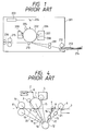
- Fig. 1 shows a sectional view of a laser beam printer representing page printers.
- Fig. 2 is a schematic block diagram of control circuit for a general laser printer.
- numeral 225 shows an information processing equipment (such as a personal computer and work station) outside a laser printer.
- An external interface 227 (such as centronics and RS232C) transmits coded or programmed image information (such as ASCII code and postscript program. These will be hereinafter called "code information") to the laser printer.
- code information is received by an interface circuit 218 within the laser printer.
- a microprocessor 217 receives the code information received by the interface circuit 218, through an internal bus 228.
- This internal bus 228 consists of a data bus, an address bus and a control bus.
- the microprocessor 217 operates in accordance with the control program within the memory 221.
- the memory 221 is a nonvoldatile ROM.
- the microprocessor 217 processes code information obtained from the interface circuit 218 to some degree, and stores in a memory 219.
- the memory 219 is a RAM for storing code information.
- the microprocessor 217 successively stores code information received from outside in a memory 219, and at the same time, converts the coded information into image information of dot image into the RAM 220.
- the RAM 220 is a memory (bit map memory) for storing image data.
- a DMA controller 222 reads out the data stored in the RAM 220, and transmits to a raster conversion circuit 224.
- the DMA controller 222 may have the internal bus 228 to itself independently of the microprocessor 17.
- the microprocessor 217 detects that the image data, which has been stored in the RAM 220, has reached data for one page (that is, when it detects that all code data for one page have been converted into image data)
- the microprocessor 217 activates the DMA controller 222).
- the DMA controller 222 and the microprocessor 217 alternately have the internal bus to each of themselves, successively read out image data from the RAM 220 in accordance with the request of the raster conversion circuit 224, and transmit the image data into the raster conversion circuit 224.
- the raster conversion circuit 224 converts the parallel image data received from the DMA controller 222 into serial image data.
- the serial image data is output into a laser driver (not shown) of a mechanical controller 226 synchronizing with the horizontal synchronizing signal to modulate the laser beam.
- the microprocessor 217 does not only develop code data in image data, but also commands various printing processes to the laser printer mechanical controller 226.
- An I/O driver 223 provides an interface between the microprocessor 217 and the mechanical controller 226.
- numeral 201 shows the main body of the laser printer.
- the microprocessor 217 develops code data for one page, and stores the image data in the memory 220. Then it rotates a carry motor (not shown) through the I/O driver 223. At this time, a photosensitive drum 202, a primary charge roller 205, a development roller 207, a transfer roller 210, a fix roller 215 and a discharge roller 216 start rotating. The rotation of the carry motor is controlled by the mechanical controller 226.
- a laser scanning device 203 has a laser scan mirror, a laser scan motor, a laser light emitting element, and a laser driving circuit within.
- the I/O driver 223 drives the carry motor, and also the laser scan motor within the laser scanning device 203.
- the I/O driver 223 successively applies a high voltage to the primary charge roller 205, the development roller 207, and the transfer roller 210.
- the I/O driver 223 also engages a clutch installed to a paper feed roller 212 to feed transfer material 213 loaded on a paper cassette 214.
- the fed transfer material 213 stops at a resist roller 211 once, and the mechanical controller 226 notifies the I/O driver 223 that the fed transfer material 213 has arrived at she resist roller 211.
- the microprocessor 217 activates the DMA controller 222.
- Serial image data is transmitted from the raster conversion circuit 224.
- the transmitted serial image data is input in the laser scanning device 203, and laser light modulated with the image data is irradiated on the sensitizing drum 202.
- a latent image is formed on its sensitizer surface, and is visualized into a toner image by a development unit 206.
- the code information thus provided by the external information processing equipment is printed on the transfer material 213 as the image information.
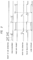
- Fig. 3 To print pages of data, printing is performed with such a timing as shown in Fig. 3.
- the microprocessor 217 starts receiving code information with timing of (a).
- the microprocessor 217 starts developing the image, and stores the image data in the memory 220.
- the microprocessor After completing the reception of the code data on the first page with timing of (b), the microprocessor continuously starts receiving the code information on the second page with timing of (c).
- the microprocessor rotates the carry motor to feed paper with timing of (f).
- the resist roller 211 is driven with timing of (g), and the DMA controller 222 starts reading out the image data with timing of (h).
- a serial image data is formed by the raster conversion circuit 224 with timing of (h) to start laser exposure.
- the laser exposure on the first page is completed with timing of (i). Also, the reception of code information on the second page has been already completed with timing of (e), and the development of image on the second page similarly starts with timing of (i). Thereafter, the printing operation for the second page is performed in the same sequence as on the first page.
- the microprocessor 217 when it has received code information for one page from an external information processing equipment 225 such as the host computer, the microprocessor 217 starts feeding transfer material 213 such as paper, and stops carry of the transfer material 213 in place to allow it to stand by.
- the microprocessor 217 successively transmits this image data of dot image to the mechanical controller 226 as serial image data, and modulates the laser light to expose an electrophotographic sensitizing drum 202, and at the same time, to resume the carry from the stand-by state so that the transfer material 213 synchronizes with the exposure image.
- the I/O driver 223 turns off the high voltage to the development roller 207 and the transfer roller 210 to level the surface of the sensitizing drum 202 to an uniform potential only by a primary charge roller 205. Thereafter, the I/O driver stops the drive of the sensitizing drum 202 and the laser scan motor, and stands by until the image development is completed.
- the drum drive and the laser scan motor rotation are started, and then a primary charged high voltage is applied to perform a preparatory operation for printing called a series of "prerotation" such as charging two surfaces of the sensitizing drum to such a state that a latent image can be formed, and adjusting the laser scanning device.
- a primary charged high voltage is applied to perform a preparatory operation for printing called a series of "prerotation" such as charging two surfaces of the sensitizing drum to such a state that a latent image can be formed, and adjusting the laser scanning device.
- a laser scanning device 203 for scanning the laser beam by a polygon mirror, etc., to irradiate the laser light modulated by the image data on the sensitizing drum 202, it is necessary to stably rotate the polygon mirror, etc. and to stably generate a horizontal synchronizing signal to synchronize in the main scan direction.
- the number of revolutions of the polygon mirror is about 6,000 rpm, and it normally takes about 10 seconds for the laser scanning device 203 to irradiate the laser light modulated with the image data.
- FIG. 4 numeral 1 is a sensitizing drum, a static latent image carrier.
- Numeral 2 is light beam emitted from a semiconductor laser.
- a charger 3 uniformly charges the sensitizing drum 1, and a developing device 4 develops a latent image.
- a transfer roller 5 transfers a developed toner image on paper, and a paper feed roller 6 feeds paper 7.
- Numeral 8 is a sensor for detecting paper.
- a resist roller 9 synchronizes the carry of paper with the start of writing an image on the sensitizing drum 1.
- a fix roller 10 fixes to paper by melting the toner transferred on paper.
- a paper detection sensor 11 detects the discharge of paper.
- a motor 12 collectively drives each of the above-mentioned roller systems, and driving transmission systems 13 to 20 such as gears transmit the driving of this motor to each roller.
- a switch mechanism 21 cuts off and connects the transmission of a power to drive a paper feed roller 6 by the motor 12, and a switch mechanism 22 cuts off and connects the transmission of a power to drive a resist roller 9 by the motor 12.
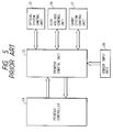
- FIG. 5 shows the control unit of a printer having such a configuration.
- a printer control unit 23 collectively controls the printing operation of the printer in accordance with the instruction from a printer controller 24.
- This printer control unit 23 requests each of the following units for driving, and receives input information: an optical system control unit 25 for controlling the drive of an optical system such as scanner control and laser drive, a high voltage control unit 26 for driving high voltage around a sensitizing drum such as charge, development, transfer and fix, and a fixer, a carry system control unit 27 for driving a paper carry system, and a sensor input unit 28 for inputting a signal from the sensor.
- an optical system control unit 25 for controlling the drive of an optical system such as scanner control and laser drive
- a high voltage control unit 26 for driving high voltage around a sensitizing drum such as charge, development, transfer and fix, and a fixer
- a carry system control unit 27 for driving a paper carry system
- a sensor input unit 28 for inputting a signal from the sensor.
- the printer control unit 23 receives an indication to a printer controller 24, communicates to notify the state of its own, and receives an image signal with a specified timing.
- the resist roller On receipt of a vertical synchronous signal thereafter, 11 the resist roller starts driving to start writing in an image. Thereafter, when the paper discharge sensor has detected the rear end of paper, the high voltage is turned off to stop the scanner motor and motor.
- the sensitizing drum was allowed to be uselessly driven.
- the sensitizing drum had to be quite uselessly rotated until the improper paper feed is judged by the printer control unit to be due to paper clogging, and especially when used in intermittent print, the life of the sensitizing drum was not provided with an optimum control.
- It is an object of the present invention is to solve each of the above-mentioned problems.
- It is another object of the present invention is to provide an image forming apparatus capable of preventing useless deterioration of a sensitizing drum.
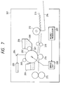
- Fig. 7 is a configuration diagram of the main body showing an image forming apparatus (laser printer) 201 of the first example.
- the configuration of the control unit for generating an image signal and controlling a printer is the same as the configuration in Fig. 2 described in the prior art, and its detailed description is omitted here.
- a feature of the first example of an image forming apparatus is to wait for completion of the image development without stopping the laser scan motor for the laser scanning device 203 though the drum drive is stopped after leveling the surface of the sensitizing drum 202 to an uniform potential only by the primary charge when a time required to convert the coded character or pattern information received from the information processing equipment from the time of starting the paper feed operation into pixel information is longer than a predetermined time Tf in order to prevent the deteriorated sensitizing drum 202 due to charging for a long time, and the surface peeling or surface flaw of the sensitizing drum 202 at a cleaner 209 due to rotation of the sensitising drum 202 for a long time, the worn cleaner 209, etc. and to prevent the lowered throughput.
- the surface of the electrophotographic sensitizer (sensitizing drum) 202 is uniformly charged by a charge roller 205, and the image is exposed to form the latent image by irradiating laser light from the laser scanning device 203 on the sensitizing drum 202 through a reflective mirror 204. Then a toner 208 within a developing device 206 is developed by a development roller 207.
- transfer material 213 loaded on a paper cassette 214 is fed by a paper feed roller 212, and stands by while its front end is held between resist rollers 211. It is fed to a transfer roller 210 so that it is synchronized with the image written on the sensitizing drum 202, and the image is transferred.
- the image transferred on the transfer material 213 is fixed by the fixer 215, and is discharged outside the machine.
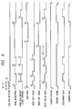
- FIG. 8 An example of timing chart for sequence operation is shown in Fig. 8. In this example, it is assumed that coded information for three pages have been received in periods (a) to (b), (i) to (j) and (p) to (q).
- the control unit including the microprocessor 217 First with reception of the code information, the development of image for code information (code information received for a period (a) to (b)) on the first page is started in the control unit including the microprocessor 217.
- the carry motor is driven with timing of (c) to drive the sensitizing drum 202 (drum drive), and at the same time, the laser scan motor is driven (scanner rotation).
- the primary charge and transfer bias are successively applied to start a preparatory operation for printing called a series of "pre-rotation” such as uniformly charging the surfaces of the sensitizing drum 202 and adjusting the laser beam output.
- a series of "pre-rotation” such as uniformly charging the surfaces of the sensitizing drum 202 and adjusting the laser beam output.
- the image data is not read out, but stands by.
- read-out of the image data starts with timing of (f). Since a time between a time (d) of starting the paper feed pickup operation and a time (e) of completing the image development is less than time Tf for the first page in this case, a signal for stopping the drum is not transmitted.
- the image is written in the sensitizing drum 202 by modulating the laser light from the laser scanning device 203.
- the resist roller 211 is driven so that the transfer material 213, which has reached the resist roller 211, is synchronized with this sensitizing drum 202 (assuming that the sensitizing drum 202 moves over a distance l 1 between the laser exposure position and the transfer roller 210 in a time T 1 and the transfer material 213 moves over a distance l 2 ( ⁇ l 1 ) between the resist roller 211 and the transfer roller 210 in a time T 2 , with timing of (g) which is late by the difference between T 1 and T 2 (T 1 - T 2 )).
- the paper feed pickup operation for the second page is being performed with timing of (k) while the image data on the first page is being read out. Since the image development for the second page is longer than the interpaper processing time, the front end of the transfer material is held between resist rollers 211, and waits for the completion of the image development in a formed loop state.
- Tf has not elapsed from the time (k) of starting the paper feed pickup operation, and therefore, the transfer material 213 is fed with timing of (n) without a drum stop signal transmitted, and the image data is read out with timing of (m).
- a paper feed pickup operation for the third page is performed with timing of (r) while the image data on the second page is being read out in the same manner as on the second page. After the image data on the second page has been read out, image development on the third page is started.
- the microprocessor 217 Since the image development on the third page has not been completed after a lapse of a period Tf from the time (r) of starting the paper feed pickup operation, the microprocessor 217 signals the stop of the drum with timing of (s).
- This signal sets the transfer bias to off, only the primary charge levels the surface of the sensitizing drum 202 to an uniform potential, and a drive unit 230 stops the drum (t). At this time, however, the scanner rotation does not stop unlike when the printer operation stops.
- the drum stop signal stops with timing of (v). This starts driving the drum again with timing of (w), the primary charge is performed, and the resist roller 11 is driven with timing of (y) to feed the transfer material 213. Since the scanner rotation has not stopped, the image data is read out with timing of (x) as soon as the surface of the sensitizing drum 202 is ready for forming a latent image.
- the transfer bias and the primary charge bias are set to off to stop the drum drive. Therefore, it is possible to prevent the deteriorated sensitizing drum 202 due to charging for a long time, and the surface peeling and flaw of the sensitizing drum 202 at a cleaner 209 due to rotation of the sensitizing drum 202 for a long time, and the worn cleaner 209.
- the laser scan motor Since the laser scan motor is rotating even while the sensitizing drum 202 is stopped, the printing speed does not lower due to the preparatory operation for the laser scanning device during restarting after the image development is completed.
- this image forming apparatus (laser printer) has not received the code information on the third page and after, no paper feed operation on the fourth page is performed.
- the transfer bias is set to off, only the primary charge levels the surface of the sensitizing drum 202 to an uniform potential, and the transfer material 213 is discharged outside the machine. Then the drum drive and scanner rotation stop to stop the printer.
- the Tf value differs with various conditions such as the material of the sensitizing drum 202, configuration of the cleaner 209, and process speed.
- a sensitizing drum obtained by dispersing phthalocyanine pigment as a charge generating layer to an aluminum cylinder 30 dia. using styrene resin as a binder, or a sensitizing drum obtained by dispersing hydrazone system compound as a charge transporting layer using polycarbonate resin as a binder is used.
- a cleaner obtained by abutting an urethane rubber blade 2 mm thick and with 65 degrees (JIS-A) in hardness at an angle of 22° in the counter direction of the sensitizing drum 202 is used.
- JIS-A degrees in hardness at an angle of 22° in the counter direction of the sensitizing drum 202
- character data in which image development is completed within three seconds, is used for nine prints out of 10 prints, and character and pattern data, in which more than 10 minutes are required to develop an image, are used for one print.
- the Tf value should be within three minutes, and preferably about 1 minute.
- the Tf value should be preferably further shorter.
- the Tf value may be 10 to 30 minutes.
- the Tf value may be automatically or manually changed in accordance with the frequency of printing, in which it takes time to develop an image.
- the Tf value is lower than the above-mentioned values.
- the Tf value may be higher.
- laser lighting to generate a horizontal synchronizing signal is preferably continued in order to eliminate the rise time for the laser scanning device 203.
- the laser lighting may be stopped after a lapse of a specified time to extend the laser life.
- timing was started with the paper feed pickup operation, but timing may be started when starting the image development, or after the paper feed pickup operation has been completed.
- a feature of the second example is to wait for completion of the image development without stopping the laser scan motor for the laser scanning device 203 though the drum drive is stopped after leveling the surface of the sensitizing drum 202 to an uniform potential only by the primary charge when a time required to convert the coded character or pattern information received from the information processing equipment from the time of starting the paper feed operation into pixel information is longer than a predetermined time Tf in order to prevent the deteriorated sensitizing drum 202 due to charging for a long time, and the surface peeling or surface flaw of the sensitizing drum 202 at a cleaner 209 due to rotation of the sensitizing drum 202 for a long time, the worn cleaner 209, etc. and to prevent the lowered throughput.
- the feature is further to wait for the completion of the image development by stopping the laser scan motor after a lapse of a specified time Ts after stopping the drive of the sensitizing drum.
- the second example shows an example in which another independent microcomputer 240 have been allowed to handle the mechanical control of the laser printer because the above-mentioned control becomes a load for the microprocessor 217.
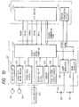
- Fig. 9 is a configuration diagram of the main body of an electrophotographic printer of the second example. Also a configuration, in which the control of the example is performed, is shown in Fig. 10.
- the configuration illustrated in Fig. 10 is divided into two: a controller unit 300 for mainly handling image information such as reception of code information for image from the external information processing equipment and image development of code information, and a printer unit 302 for controlling the operation of the printer proper.
- the mechanical control of the laser printer is performed by a single chip microcomputer 240.
- the microcomputer 240 there are a motor driver 241, a laser scan motor driver 243, a paper feed clutch 245, a resist roller clutch 246, a sensor 247, a high voltage output circuit 248, a laser modulator 249, a beam detector 251, etc.
- the microcomputer 240 controls those loads in accordance with a command from an I/O driver 223.
- the READY, PRINT, VSREQ, VSYNC, and PRFD signals are transmitted and received between the microcomputer 240 and the I/O driver 223.
- a serial communication line is also prepared to notify the I/O driver 223 of a state of loading of the printer, and to transmit a special command from the I/O driver 223 to the microcomputer 240.
- An image signal (VIDEO signal) output from a raster conversion circuit 224 is input into a laser modulator 249, and beam output from a semiconductor laser 250 is modulated in accordance with the VIDEO signal.
- the laser beam is scanned by the laser scan mirror, and the scanned laser beam falls upon a photodiode 252 located on a scanning path for the laser beam.
- the laser beam is converted into a pulse signal by a beam detector 251.
- the pulse signal output from the beam detector is input into the raster conversion circuit 224 as a horizontal synchronizing signal (HSYNC signal).
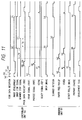
- the ready signal RDY is true.
- the controller unit 300 transmits a print signal PRINT to the printer unit 301 with timing of (c).
- the printer unit 301 starts the drum drive and scanner rotation, and successively performs the primary charge, etc. to prepare receiving an image signal.
- the paper feed pickup is also performed with timing of (d), and the front end of the transfer material 213 reaches the resist rollers 211.
- timing of (e) in which a loop is formed, the VSREQ is made true to notify the controller unit 300 that the printer unit 301 is ready for receiving an image signal.
- the printer unit 301 waits for an image signal to be transmitted in this state.
- the image for the code information is developed in the controller unit 300.
- the controller unit 300 transmits VSYNC notifying of the start of the image data transmission with timing of (f), in which the VSREQ is true.
- the image data is read out, and is transmitted to the printer unit 301 as a video signal (VDO) in a period (g) to (h).
- the transfer material 213, which has stood by is fed to the sensitizing drum 202 by timing to synchronize the front end of the image to that of the transfer material 213 through the drive of the resist rollers 211 with timing of (i), and is transferred by a transfer roller 210.
- the controller unit 300 has received code information on the second page in a period (j) to (k), and transmits a prefeed signal (PRFD) to start the paper feed operation irrespective of the operation of the image development means with timing of (1).
- PRFD prefeed signal
- the paper feed pickup is performed with timing of (m), in which the maximum throughput can be obtained from this laser printer.
- the front end of the transfer material 213 reaches the resist rollers 211, and the VSREQ signal is made true to notify the controller that the printer unit is ready for receiving an image signal with timing of (n) in which a loop is formed.
- the printer unit 301 waits for an image signal to be transmitted in this state.
- the image for the code information is developed in the controller unit 300. Since the image development has not been completed after a lapse of Tf from the paper feed pickup operation (m), a drum stop signal is transmitted with timing of (o).
- the single chip microcomputer 240 turns off the primary charge with timing of (p), and stops the drum drive through the motor driver 241 (q).
- the controller unit 300 Since the image development of the controller unit 300 has not been completed after a lapse of Ts from stopping the drum drive, the controller unit 300 transmits a scanner stop signal with timing of (r).
- the single chip microcomputer 240 stops the scanner rotation through the laser scan motor driver 243 (s).
- the controller unit 300 stops the drum stop and scanner stop signals, and the single chip microcomputer 340 in the printer unit 301 resumes the drum drive by rotating the carry motor through the motor driver 341 with timing of (u), and at the same time, resumes also the scanner rotation through the laser scan motor driver 343.
- the primary charge is resumed with timing of (v), and when the laser scanning device is ready for operation thereafter, a VSREQ signal is transmitted.
- the controller unit 300 transmits a VSYNC signal to the printer unit, and the printer unit 301 drives the resist rollers 211 to transfer, on the transfer material 213, the read-out (VDO) image for the image in the controller unit.
- the printer unit 301 enters the post-rotation, and stops the primary charge, drum drive and scanner rotation to complete the operation.
- the Tf value may be determined like the first embodiment.
- the Ts value is determined in accordance with the life of the laser scan motor, especially the life of the polygon mirror bearing.
- a value of (Tf + Ts) is desirable to be within three minutes at a number of revolutions of 6,000 rpm using ball bearings. If three minutes are exceeded when the frequency of print with long image development time is very high, runout occurs on the polygon mirror surface, and the image is uneven in the subscan direction.
- the value of (Tf + Ts) may be changed in accordance with this frequency. If a polygon mirror bearing with such a long life as a thrust bearing is used, the value of (Tf + Ts) may be extended to about ten times as long as the ball bearing.
- controller unit 300 Since the controller unit 300 is separated from the printer unit 301, the embodiment can be widely applied to hosts having various page descriptive languages. Also since the control unit 300 is capable of operating irrespective of the paper feed timing of the printer unit 301, the control is simple.
- a feature of the first embodiment according to the present invention is that the controller signals the start of the paper feed operation before coded character or pattern information is received from the information processing equipment in a stand-by state, in which the print operation is available at any time, and that the printer starts the paper feed operation in compliance with this signal and at the same time, starts the scanner rotation before the sensitizing drum 202 is driven.
- control unit for the image forming apparatus The configuration of the control unit for the image forming apparatus is the same as Fig. 10 of the second example, and its description is omitted.
- the ready signal RDY is true.
- the controller unit 300 transmits a prefeed signal PRFD, a signal for starting the paper feed operation, to the printer unit with timing of (a).
- the printer unit 301 Upon receipt of it, the printer unit 301 starts the scanner rotation and the paper feed pickup with timing of (b), and enters a so-called "stand-by" state.
- the controller unit 300 After it has received code information for one page in a period (c) to (d) hereafter, the controller unit 300 transmits a print signal PRT to the printer unit 301 with timing of (e).
- the printer unit 301 Upon receipt of it, the printer unit 301 performs the drum drive and the primary charge at the same time (f), and makes the VSREQ true to notify the controller unit 300 that the printer unit is ready for receiving an image signal (g).
- the image for the code information is developed in the controller unit 300.
- the controller unit 300 transmits VSYNC notifying of the start of the image data transmission with timing of (h), in which the VSREQ is true.
- the image data is read out, and is transmitted to the printer unit 301 as a video signal (VDO) in a period (i) to (j).
- the transfer material 213, which has stood by is fed to the sensitizing drum 202 by timing to synchronize the front end of the image to that of the transfer material 213 through the drive of the resist rollers 211 with timing of (k), and is transferred by a transfer roller 210.
- the printer unit 301 After the image data has been read out, the printer unit 301 enters the post-rotation, and stops the primary charge, scanner rotation and drum drive to complete the operation because the controller unit 300 has received neither a reserve for the next printing nor code information.
- a time from the reception of code information to completion of printing can be shortened because the scanner rotation is started before driving the drum for printing.
- the scanner rotation may be once stopped when the image development has not been completed even if a specified time passed from the prefeed signal PRFD.
- the controller output the prefeed signal PRFD in accordance with the command from an external equipment in this embodiment
- the prefeed signal may be output in accordance with the received code information for one page, for example, to enter a stand-by state.
- a feature of the second embodiment according to the present invention is that the rotary speed R1 of the scanner in a period for waiting for the image development in the first and second examples and a period for waiting for a print signal PRT after the prefeed signal PRFD in the third embodiment is reduced less than the rotary speed R2 in a period for reading out the image data.
- the rise time of the scanner rotation greatly depends on a low rotary speed range of the laser scan motor immediately after the start, the rise time of the laser scanning device 203 to the rotary speed R2 can be remarkably shortened by leaving the scanner rotated at the rotary speed R1 in the above-mentioned period.
- This embodiment is effective to prevent noise in addition to extending the life of the laser scanning device 203.
- the above embodiments are a case where the paper feed operation is performed before driving the photosensitive drum.
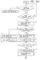
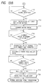
- Third Embodiment Fig. 13 shows a sequence when the printer control unit 127 has received, from the printer controller 128, a spare paper feed signal, that is, such a signal that, unlike the print start signal, carries paper to a specified place, allows it to stand by at the position, and thereafter prints through a print start signal.
- a spare paper feed signal that is, such a signal that, unlike the print start signal, carries paper to a specified place, allows it to stand by at the position, and thereafter prints through a print start signal.
- step T1 on receipt of a spare paper feed signal (steps T1, T2) before receiving the print start signal, drive the second motor (step T3) without driving the scanner motor to feed paper (steps T5 to T9) in the same manner as the above-mentioned operation.
- step T10 stop the paper feed and the second motor (steps T10, T11), and wait for a print signal (step T12).
- step T13, T14 On receipt of the print signal, drive the first and second motors and the scanner motor (steps T13, T14), and when the scanner motor reaches a normal number of revolutions (step T15), perform high voltage sequences in order (step T16).
- step T17 drive the paper feed roller again (step T17), and then perform the same operation as in the above-mentioned embodiment (steps T18 to T20).
- the print start signal is output by synchronizing with the completed pixel conversion, and the scanner motor is ensured to be driven when the print start signal is received (when starting to drive the sensitizing drum).
- the scanner-motor is driven through the print start signal, and the drive of the sensitizing drum has been started after a lapse of a specified time from the reception of the print start signal.
- both may be optionally combined.
Claims (10)
- Bilderzeugungsvorrichtung mit einer Bilderzeugungseinrichtung (202 bis 210) zur Ausbildung eines Bilds auf einer drehbaren Bildtrommel (202) in Übereinstimmung mit von einer Datenquelle empfangenen Bilddaten, undeiner Zuführungseinrichtung (202) zur Zuführung eines Bogens, auf welchen das auf der sich drehenden Bildtrommel ausgebildete Bild zu übertragen ist,
gekennzeichnet durcheine Druckereinheit (300), welche bei Gebrauch ein Drucksignal (PRNT) erzeugt, wenn die Bilddaten für eine Seite empfangen werden, der Zuführungseinrichtung ein Papierzuführungssignal zuführt, ohne die Bildtrommel zu starten, bevor das Drucksignal erzeugt wird, und der Bildtrommel ein Trommelantriebssignal zuführt, wenn das Drucksignal erzeugt wird. - Bilderzeugungsvorrichtung gemäß Anspruch 1,die ferner die Datenquelle aufweist,wobei die Datenquelle eine Eingabeeinrichtung zur Eingabe von Kodeinformationen aus einer externen Vorrichtung und eine Einrichtung zur Umwandlung der Eingabe-Kodeinformation in die Bildelementdaten aufweist.
- Bilderzeugungsvorrichtung gemäß Anspruch 2,bei welcher die Zuführungseinrichtung dazu geeignet ist, einen nächsten Bogen zuzuführen, selbst wenn die Umwandlung der Kodeinformation einer nachfolgenden Seite abgeschlossen ist.
- Bilderzeugungsvorrichtung gemäß Anspruch 1,bei welcher die Bilderzeugungsvorrichtung eine Lichtstrahl-erzeugende Einrichtung zur Erzeugung eines auf der Basis der Bildelementinformation modulierten Lichtstrahls und eine Lichtstrahl-ablenkende Einrichtung zur Überstreichung des Bildträgers mit dem durch die Lichtstrahlerzeugende Einrichtung erzeugten Lichtstrahl aufweist, undbei welcher, wenn das festgelegte Signal während des Stopps eines Lichtstrahl-ablenkenden Vorgangs der Lichtstrahl-ablenkenden Einrichtung ausgegeben wird, der Lichtstrahl-ablenkende Vorgang in Antwort auf das Papierzuführungssignal gestartet wird.
- Bilderzeugungsvorrichtung gemäß Anspruch 4,bei welcher die Zuführungseinrichtung den in eine festgelegte stromaufwärts gelegene Position der Bilderzeugungseinrichtung zugeführten Bogen stoppt.
- Bilderzeugungsvorrichtung gemäß Anspruch 5,die ferner eine Einrichtung aufweist, die bestimmt, ob eine nachfolgende Seite der Bildelementdaten erzeugt wird oder nicht.
- Bilderzeugungsvorrichtung gemäß Anspruch 6,bei welcher die Bestimmungseinrichtung bestimmt, daß die Bildelementdaten auf der Basis der Druckdaten erzeugt werden.
- Bilderzeugungsvorrichtung gemäß Anspruch 7,bei welcher die Lichtstrahl-ablenkende Einrichtung mit einer geringen Geschwindigkeit arbeitet, wenn abgewartet wird, daß das Trommelantriebssignal ausgegeben wird.
- Bilderzeugungsvorrichtung gemäß Anspruch 6,bei welcher die Betätigung der Lichtstrahl-ablenkenden Einrichtung für eine festgelegte Zeit in einem Zustand, in welchem der Bogen in einer festgelegten Position gestoppt ist, gestoppt wird, wenn die Bestimmungseinrichtung nicht bestimmt, daß die nachfolgende Seite der Bildelementdaten erzeugt wird.
- Bilderzeugungsvorrichtung gemäß Anspruch 9,bei welcher der Lichtstrahl-ablenkende Vorgang gestartet wird, wenn die Bestimmungseinrichtung bestimmt, daß die Bildelementdaten während des Stopps des Lichtstrahlablenkenden Vorgangs erzeugt werden.
Applications Claiming Priority (6)
| Application Number | Priority Date | Filing Date | Title |
|---|---|---|---|
| JP12819190 | 1990-05-17 | ||
| JP2128191A JP2840380B2 (ja) | 1990-05-17 | 1990-05-17 | 画像形成装置 |
| JP128191/90 | 1990-05-17 | ||
| JP192270/90 | 1990-07-19 | ||
| JP2192270A JPH0477756A (ja) | 1990-07-19 | 1990-07-19 | 画像形成装置 |
| JP19227090 | 1990-07-19 |
Publications (3)
| Publication Number | Publication Date |
|---|---|
| EP0457330A2 EP0457330A2 (de) | 1991-11-21 |
| EP0457330A3 EP0457330A3 (de) | 1994-01-12 |
| EP0457330B1 true EP0457330B1 (de) | 2000-02-09 |
Family
ID=26463927
Family Applications (1)
| Application Number | Title | Priority Date | Filing Date |
|---|---|---|---|
| EP91107970A Expired - Lifetime EP0457330B1 (de) | 1990-05-17 | 1991-05-16 | Bilderzeugungsgerät |
Country Status (4)
| Country | Link |
|---|---|
| US (1) | US5694158A (de) |
| EP (1) | EP0457330B1 (de) |
| DE (1) | DE69131970T2 (de) |
| HK (1) | HK1011746A1 (de) |
Families Citing this family (11)
| Publication number | Priority date | Publication date | Assignee | Title |
|---|---|---|---|---|
| KR0146533B1 (ko) * | 1995-08-14 | 1998-08-17 | 김광호 | 화상기록장치의 프린트 제어방법 |
| US5819149A (en) * | 1995-11-01 | 1998-10-06 | Canon Kabushiki Kaisha | Image forming apparatus preventing change of size of image |
| US5701549A (en) * | 1996-01-22 | 1997-12-23 | Lexmark International, Inc. | Image forming apparatus with modular staging assembly |
| US5978643A (en) * | 1996-03-21 | 1999-11-02 | Ricoh Company, Ltd. | Electrophotographic apparatus which reduces running cost by starting image forming processes in response to sheet detectors |
| JP3767026B2 (ja) * | 1996-08-26 | 2006-04-19 | ブラザー工業株式会社 | 多機能周辺装置および記憶媒体 |
| AU2001231078A1 (en) * | 2000-01-25 | 2001-08-07 | Vistaprint Usa, Inc. | Managing print jobs |
| US6694110B2 (en) * | 2001-02-19 | 2004-02-17 | Canon Kabushiki Kaisha | Image forming apparatus with variable waiting time conveyance feature |
| JP3728216B2 (ja) * | 2001-04-12 | 2005-12-21 | キヤノン株式会社 | 画像形成装置 |
| US6706118B2 (en) * | 2002-02-26 | 2004-03-16 | Lexmark International, Inc. | Apparatus and method of using motion control to improve coatweight uniformity in intermittent coaters in an inkjet printer |
| US7111916B2 (en) * | 2002-02-27 | 2006-09-26 | Lexmark International, Inc. | System and method of fluid level regulating for a media coating system |
| US6955721B2 (en) * | 2002-02-28 | 2005-10-18 | Lexmark International, Inc. | System and method of coating print media in an inkjet printer |
Family Cites Families (18)
| Publication number | Priority date | Publication date | Assignee | Title |
|---|---|---|---|---|
| US4786923A (en) * | 1982-09-07 | 1988-11-22 | Canon Kabushiki Kaisha | Image recording system for image recording in response to signals entered from a recording information generating unit |
| JPS60113253A (ja) * | 1983-11-24 | 1985-06-19 | Canon Inc | 記録装置 |
| JPH0612382B2 (ja) * | 1984-02-15 | 1994-02-16 | キヤノン株式会社 | レ−ザビ−ムプリンタ |
| US4578689A (en) * | 1984-11-26 | 1986-03-25 | Data Recording Systems, Inc. | Dual mode laser printer |
| US4933772A (en) * | 1985-10-07 | 1990-06-12 | Minolta Camera Kabushiki Kaisha | Electrophotographic printer with improved timing arrangements |
| JPH0736600B2 (ja) * | 1985-10-11 | 1995-04-19 | 株式会社リコー | レ−ザ記録装置の露光装置 |
| JPS62187361A (ja) * | 1986-02-14 | 1987-08-15 | Canon Inc | 画像形成装置 |
| JPS63124786A (ja) * | 1986-11-14 | 1988-05-28 | Canon Inc | モ−タ制御装置 |
| JPS6438345A (en) * | 1987-07-31 | 1989-02-08 | Toshiba Corp | Picture forming device |
| JPH0764091B2 (ja) * | 1987-10-05 | 1995-07-12 | 沖電気工業株式会社 | 電子写真プリンタ |
| US4914456A (en) * | 1987-10-23 | 1990-04-03 | Matsushita Electric Industrial Co., Ltd. | Electrostatographic apparatus |
| JP2675811B2 (ja) * | 1988-04-20 | 1997-11-12 | キヤノン株式会社 | 光ビームプリンタ |
| JPH01284876A (ja) * | 1988-05-12 | 1989-11-16 | Ricoh Co Ltd | 記録装置 |
| JP2685522B2 (ja) * | 1988-08-05 | 1997-12-03 | 株式会社日立製作所 | 高精度画像記録装置 |
| DE68925022T2 (de) * | 1988-09-27 | 1996-06-13 | Canon Kk | Aufzeichnungsgerät. |
| JP2755625B2 (ja) * | 1988-10-31 | 1998-05-20 | 株式会社東芝 | 画像形成装置 |
| JPH02141770A (ja) * | 1988-11-22 | 1990-05-31 | Mita Ind Co Ltd | デジタル画像形成装置 |
| CN1058577C (zh) * | 1989-07-28 | 2000-11-15 | 佳能株式会社 | 图象形成装置 |
-
1991
- 1991-05-16 DE DE69131970T patent/DE69131970T2/de not_active Expired - Fee Related
- 1991-05-16 EP EP91107970A patent/EP0457330B1/de not_active Expired - Lifetime
-
1995
- 1995-03-23 US US08/409,937 patent/US5694158A/en not_active Expired - Lifetime
-
1998
- 1998-12-03 HK HK98112757A patent/HK1011746A1/xx not_active IP Right Cessation
Also Published As
| Publication number | Publication date |
|---|---|
| EP0457330A2 (de) | 1991-11-21 |
| DE69131970D1 (de) | 2000-03-16 |
| US5694158A (en) | 1997-12-02 |
| EP0457330A3 (de) | 1994-01-12 |
| HK1011746A1 (en) | 1999-07-16 |
| DE69131970T2 (de) | 2000-07-20 |
Similar Documents
| Publication | Publication Date | Title |
|---|---|---|
| EP0681265B1 (de) | Bilderzeugungsgerät | |
| EP0457330B1 (de) | Bilderzeugungsgerät | |
| US5512927A (en) | Image forming apparatus having a photosensitive drum rotatable at different speeds | |
| JPH1115216A (ja) | 画像処理装置およびその制御方法、並びに、記録媒体 | |
| EP0466172B1 (de) | Blattzufuhr für Bilderzeugungsgerät | |
| JP3015076B2 (ja) | 画像形成装置 | |
| JPH0411392B2 (de) | ||
| JP3303382B2 (ja) | 画像形成装置 | |
| JP2710365B2 (ja) | 画像記録装置 | |
| JP2840380B2 (ja) | 画像形成装置 | |
| JP3342689B2 (ja) | 画像形成装置およびその制御方法 | |
| JPH0216519B2 (de) | ||
| JP3081233B2 (ja) | 画像形成装置 | |
| JP3171194B2 (ja) | 画像記録装置 | |
| EP0398294B1 (de) | Elektrophotographisches Druckgerät | |
| JPH04143773A (ja) | 画像形成装置 | |
| JPS59143162A (ja) | 記録装置 | |
| JP2750977B2 (ja) | 印刷装置 | |
| JP2839902B2 (ja) | デジタル複写機 | |
| KR100242121B1 (ko) | 전사전압 제어방법 | |
| JPH0429255A (ja) | 画像形成装置の制御方法 | |
| JP2874766B2 (ja) | システム装置の制御装置 | |
| JPH04354465A (ja) | 画像形成装置 | |
| JPH03178259A (ja) | 画像形成装置 | |
| JPH10319331A (ja) | 画像形成装置 |
Legal Events
| Date | Code | Title | Description |
|---|---|---|---|
| PUAI | Public reference made under article 153(3) epc to a published international application that has entered the european phase |
Free format text: ORIGINAL CODE: 0009012 |
|
| AK | Designated contracting states |
Kind code of ref document: A2 Designated state(s): DE FR GB IT |
|
| PUAL | Search report despatched |
Free format text: ORIGINAL CODE: 0009013 |
|
| AK | Designated contracting states |
Kind code of ref document: A3 Designated state(s): DE FR GB IT |
|
| 17P | Request for examination filed |
Effective date: 19940530 |
|
| 17Q | First examination report despatched |
Effective date: 19941004 |
|
| GRAG | Despatch of communication of intention to grant |
Free format text: ORIGINAL CODE: EPIDOS AGRA |
|
| GRAG | Despatch of communication of intention to grant |
Free format text: ORIGINAL CODE: EPIDOS AGRA |
|
| GRAH | Despatch of communication of intention to grant a patent |
Free format text: ORIGINAL CODE: EPIDOS IGRA |
|
| GRAH | Despatch of communication of intention to grant a patent |
Free format text: ORIGINAL CODE: EPIDOS IGRA |
|
| GRAA | (expected) grant |
Free format text: ORIGINAL CODE: 0009210 |
|
| AK | Designated contracting states |
Kind code of ref document: B1 Designated state(s): DE FR GB IT |
|
| REF | Corresponds to: |
Ref document number: 69131970 Country of ref document: DE Date of ref document: 20000316 |
|
| ET | Fr: translation filed | ||
| ITF | It: translation for a ep patent filed |
Owner name: SOCIETA' ITALIANA BREVETTI S.P.A. |
|
| PLBE | No opposition filed within time limit |
Free format text: ORIGINAL CODE: 0009261 |
|
| STAA | Information on the status of an ep patent application or granted ep patent |
Free format text: STATUS: NO OPPOSITION FILED WITHIN TIME LIMIT |
|
| 26N | No opposition filed | ||
| REG | Reference to a national code |
Ref country code: GB Ref legal event code: IF02 |
|
| PGFP | Annual fee paid to national office [announced via postgrant information from national office to epo] |
Ref country code: FR Payment date: 20090520 Year of fee payment: 19 Ref country code: DE Payment date: 20090531 Year of fee payment: 19 Ref country code: IT Payment date: 20090515 Year of fee payment: 19 |
|
| PGFP | Annual fee paid to national office [announced via postgrant information from national office to epo] |
Ref country code: GB Payment date: 20090527 Year of fee payment: 19 |
|
| GBPC | Gb: european patent ceased through non-payment of renewal fee |
Effective date: 20100516 |
|
| REG | Reference to a national code |
Ref country code: FR Ref legal event code: ST Effective date: 20110131 |
|
| PG25 | Lapsed in a contracting state [announced via postgrant information from national office to epo] |
Ref country code: IT Free format text: LAPSE BECAUSE OF NON-PAYMENT OF DUE FEES Effective date: 20100516 |
|
| PG25 | Lapsed in a contracting state [announced via postgrant information from national office to epo] |
Ref country code: DE Free format text: LAPSE BECAUSE OF NON-PAYMENT OF DUE FEES Effective date: 20101201 |
|
| PG25 | Lapsed in a contracting state [announced via postgrant information from national office to epo] |
Ref country code: FR Free format text: LAPSE BECAUSE OF NON-PAYMENT OF DUE FEES Effective date: 20100531 |
|
| PG25 | Lapsed in a contracting state [announced via postgrant information from national office to epo] |
Ref country code: GB Free format text: LAPSE BECAUSE OF NON-PAYMENT OF DUE FEES Effective date: 20100516 |