EP0454819B1 - Verfahren und vorrichtung zur kompandierung eines signals - Google Patents
Verfahren und vorrichtung zur kompandierung eines signals Download PDFInfo
- Publication number
- EP0454819B1 EP0454819B1 EP90916848A EP90916848A EP0454819B1 EP 0454819 B1 EP0454819 B1 EP 0454819B1 EP 90916848 A EP90916848 A EP 90916848A EP 90916848 A EP90916848 A EP 90916848A EP 0454819 B1 EP0454819 B1 EP 0454819B1
- Authority
- EP
- European Patent Office
- Prior art keywords
- signal
- circuit
- output
- offset
- companding
- Prior art date
- Legal status (The legal status is an assumption and is not a legal conclusion. Google has not performed a legal analysis and makes no representation as to the accuracy of the status listed.)
- Expired - Lifetime
Links
Images


Classifications
-
- H—ELECTRICITY
- H04—ELECTRIC COMMUNICATION TECHNIQUE
- H04N—PICTORIAL COMMUNICATION, e.g. TELEVISION
- H04N5/00—Details of television systems
- H04N5/14—Picture signal circuitry for video frequency region
- H04N5/20—Circuitry for controlling amplitude response
-
- H—ELECTRICITY
- H04—ELECTRIC COMMUNICATION TECHNIQUE
- H04N—PICTORIAL COMMUNICATION, e.g. TELEVISION
- H04N9/00—Details of colour television systems
- H04N9/64—Circuits for processing colour signals
- H04N9/68—Circuits for processing colour signals for controlling the amplitude of colour signals, e.g. automatic chroma control circuits
Definitions
- the present invention relates in general to a method and apparatus for accomplishing signal companding.
- the present invention is directed to a method and apparatus that employs log-offset compression to accomplish signal companding.
- the invention is particularly useful in video signal processing circuitry for HDTV Telecine machines, video cameras and the like.
- Telecine machines are devices which are used to convert images present on motion picture film to a video image signal.
- One of the most popular type of telecine machine employs CCD line scanners and digital signal processing techniques to scan and convert the film image.
- CCD line scanners and digital signal processing techniques to scan and convert the film image.
- the popularity of telecine machines employing CCD scanners and digital signal processing is due in part to the high reliability attributable to the CCD devices and the high picture quality which can be obtained through the use of digital signal processing techniques.
- CCD line scanners to HDTV telecine machines, however, present special problems due to the substantially higher signal bandwidth required by HDTV systems.
- CCD telecinemachines typically employ one or more CCD sensors featuring an imaging array of 1728 and 2048 pixels and requiring clock rates in excess of 50 MHz.
- A/D analog-to-digital
- Current state of the art monolithic A/D converters are limited to an operating range of about a nine bit resolutions sampling at 30 Msamp/sec.; far below what is needed in the implementation of a digital CCD telecine machine. Higher resolution capability is therefore required in order to reduce the effects of quantization noise at low signal amplitudes.
- Signal companding can be employed to overcome the quantization limitations of currently available A/D converters. Signal companding prior to digitizing permits the quantization steps to be tapered to provide a uniform signal to noise (S/N) ratio over a larger dynamic range than would be possible if the signal were not compressed.
- S/N signal to noise
- Logarithmic amplifiers are commonly used in video systems for scanning film and in many applications where a large dynamic range is required. There are disadvantages, however, associated with the use of logarithmic amplifiers in signal companding circuits for HDTV telecine machines. Logarithmic amplifiers are extremely sensitive to thermal changes at low signal levels and thus require a stable temperature environment or a temperature compensation network. To some extent, temperature problems associated with logarithmic amplifiers have been compensated for by keeping the logging transistor in thermal equilibrium using a black feedback clamp to adjust the logging transistor's current to zero during the black reference period of the video signal. In addition to temperature sensitivity, however, logarithmic amplifiers also commonly have bandwidth or settling time problems at low signal levels.
- the invention provides a method and apparatus for signal companding that incorporates a log-offset companding technique to provide both a high bandwidth over the dynamic range of the signal being processed as well as temperature stability.
- the incorporation of log-offset companding technique provides the capability of generating a family of transfer curves. The ability to provide a family of transfer curves is particularly useful, for example, in telecine machines adapted to scan more than one type of film.
- the present invention provides a video signal processing circuit for generating an output video signal corresponding to a plurality of transfer curves from an input video signal, comprising companding means including a logarithmic amplifier, a feedback circuit comprising a compression ratio adjustment circuit and a sampling circuit for sampling said output video signal, wherein said feedback circuit generates an offset signal based on said output video signal and a reference signal supplied by said compression ratio adjustment circuit, and a summing circuit coupled to said logarithmic amplifier for summing said input video signal and said offset signal supplied by said feedback circuit, thereby generating the selected transfer curve.
- companding means including a logarithmic amplifier, a feedback circuit comprising a compression ratio adjustment circuit and a sampling circuit for sampling said output video signal, wherein said feedback circuit generates an offset signal based on said output video signal and a reference signal supplied by said compression ratio adjustment circuit, and a summing circuit coupled to said logarithmic amplifier for summing said input video signal and said offset signal supplied by said feedback circuit, thereby generating the selected transfer
- the log-offset compression technique is actually a generalization of a logarithmic amplifier, which uses a black feedback clamp stabilization network, in which a signal dependent current is sinked or sourced into a collector or emitter of a bipolar junction transistor and the resultant voltage on the base emitter junction is sensed. Since the relationship between the collector or emitter current and the base-emitter voltage is logarithmic, a logarithmic output voltage results if the transistor current is directly related to the information signal.
- Fig. 1 illustrates a transistor model along with the Ebers Moll and transistor equations that define the above logarithmic operation.
- the Ebers Moll equation has two temperature dependent terms (Is and Vt).
- the logging transistor must be kept in thermal equilibrium. This is usually accomplished by either a temperature stabilizer (component oven), transistor heater circuit or a temperature compensation network.
- a black feedback clamp network is used to adjust the logging transistor's current to substantially zero during the black reference period of the video signal. The feedback network will then maintain logarithmic calibration even when operating conditions occur outside the feedback loop change.
- Log-offset compression is similar to logarithmic compression set forth above except that the transistor current is adjusted to apredetermined reference level to generate a desired transfer curve.
- the transistor current is adjusted during the black reference period of a video signal. This changes the overall dynamic range of the transistor current, thereby causing the logging transistor to operate over a narrower current range.
- a family of different transfer curves can be generated by varying the black reference current level.
- Fig. 2 illustrates a log-offset companding circuit that includes a logarithmic amplifier 10, a summing circuit 12, a feedback circuit 11 (that includes an integrator circuit 14, a compression ratio adjustment circuit 15, a sampling network 16) and an output buffer 18.
- a video input signal (Vin) is supplied to the summing circuit 12 along with an offset signal (Vfb) that is supplied from the feedback circuit 11.
- the logarithmic amplifier 10 includes a bipolar logging transistor 22 that is employed to obtain an outputsignal Vout that is representative of a logarithmic transfer curve.
- the compression ratio adjustment circuit 15 is set to a desired level.
- the output from the ratio adjustment circuit 15 is supplied to the integrator circuit 14 along with a sampling of the output signal from the logarithmic amplifier 10 that is supplied by the sampling network 16.
- the sampling network 16 samples the output signal Vout during the black reference interval of the input video signal.
- the logging transistor's 22 collector current is modulated based on the dc offset provided to the summing circuit 12 in addition to a current that is proportional to the input signal. This results in a nominal collector current even in the absence of an input video signal which in turn enhances temperature stability.
- the dc offset can be used as a variable to modify the log-offset compandor's transfer characteristic.
- the single log-offset compandor can generate an entire family of transfer curves.
- a log curve and an offset log curve can be generated for use in telecine machines to scan different types of films
- a SMPTE compression curve recommended for use in video cameras can be generated, as well as a square root, L* and cube root curves.
- the log-offset compandor illustrated in Fig. 2 can be readily adapted for use in many video applications requiringsignal companding including telecine machines, video cameras, as well as to provide gamma correction in video processing circuits.
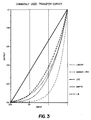
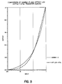
- Fig. 3 illustrated commonly used transfer curves
- Fig. 4 illustrates the use of various offsets to approximate the curves illustrated in Fig. 3.
- logarithmic amplifiers have bandwidth or settling time problems at low signal levels.
- the Gummel plot of a transistor typically indicates five or more decades of logarithmic operation.
- the collector current is decreased about two decades below its peak amplitude, the Ft of the transistor will decrease dramatically. This causes a signal dependent bandwidth which degrades rapidly below the second decade.
- the log-offset compandor uses an offset to create its transfer characteristic.
- modulation of the logging transistor's collector current has a greatly reduced dynamic range. The net result is a significant speed improvement at low Vi input signal levels.
- logarithmic compression results in quantization steps that are proportional to the input signal level.
- the input referred signal to quantization noise ratio is independent of the input signal level.
- Linear quantization has an input referred signal to quantization noise that is directly dependent on the input signal level as the quantization step size is fixed.
- log-offset compression is a cross between logarithmic and linear quantization. The amount of offset will trade off S/N (quantization) improvement, when compared with logarithmic compression, at high signal levels for degradation at low levels.
- log-offset compression takes advantage of the fact that the system S/N is dominated by sensor noise at low signal levels and by quantization noise at high signal levels.
- a telecine machine incorporating the log-offset companding circuit illustrated in Fig. 2 including a film transport 20 that advances a motion picture film 23 at variable speeds through a film gate 24 from a supply reel 26 to a take-up reel 28.
- a light source 30 generates a light beam that is directed to a line converter 32 and focused upon a linear section of the film 23 in the film gate 24.
- the light is modulated by the image on the film 23 and is transmitted through an objective lens 34 to a beam splitter 36 that transmits the modulated light to each of three CCD line sensors 38r, 38g, 38b.
- Red, green and blue filters 40r, 40g, 40b are respectively provided in front of the CCD line sensors so that the output signals generated from the sensors correspond to the red, green and blue components of the modulated light.
- a film speed sensor 50 is provided to monitor the speed of the film as it passes through the film gate, and supplies a signal indicative thereof to a film scanner control unit 52.
- the film scanner control unit 52 is also coupled to an operator control panel 54 that includes a film transport speed control 53 and a film type control 55. Signals indicative of the desired film speed and film type are supplied by the operator control panel 54 to the film scanner control unit 52.
- Each CCD line sensor 38r, 38g, 38b includes a linear array of active photosites 42r, 42g, 42b, a transfer gate 44r, 44g, 44b and a horizontal output shift register 46r, 46g, 46b. Image charge accumulated in the active photosites of the respective linear arrays is transferred to the respective horizontal output shift registers 46r, 46g, 46b by applying a gate signal to the respective transfer gate 44r, 44g, 44b.
- the sensor clock 48 provides the gate signal to the transfer gates 44r, 44g, 44b to effect charge transfer.
- the sensor clock generator 48 provides a clock signal of predetermined frequency for shifting the respective image signals from the horizontal output shift registers.
- the output signals from the CCD sensors are supplied to a video signal processing circuit 60 which converts and formats the signals received from the sensors to a desired video signal format.
- the output signal from the video processing circuit is supplied to both a video recorder unit 64, a display monitor 62 and to any other external device desired.
- FIG. 8 A block diagram of the video signal processing circuit 60 is shown in Fig. 8.
- the processing circuit 60 includes three log-offset companding circuits 70-74 (of the type shown in Fig. 2) which receive the signals generated by the CCD line sensors 38r, 38g, 38b.
- the output from the companding circuits 70-74 are then supplied to an A/D converter unit 76.
- the output from the A/D converter unit 76 is subsequently supplied to additional video processing circuitry 78, for example gamma correction circuitry, chrominance matrix, etc., which generates the output video signal.
- Each of the log-offset companding circuits 70-74 is coupled to the film scanner control unit 52.
- the film scanner control unit 52 sends a signal to the compression ratio adjustment circuit of each of the companding circuits 70-74 in order to select a desired transfer curve based on the type of film being scanned. For example, a log transfer curve can be used for negative film while a log-offset curve is used for print film.
- a look-up-table (LUT) to translate the log-offset curve back to a log curve prior to the completion of signal processing.
- LUT look-up-table
- a LUT 80 is provided between the A/D converter unit 76 and the video processingcircuitry 78.
- the LUT 80 converts the log-offset signal from the A/D converter unit 76 to a log signal which is then provided to the video processing circuitry 78.
- the use of the LUT 80 is of particular benefit when the video processing circuitry 78 is capable of handling only log data.
- the invention is particularly applicable to HDTV telecine systems, it will be readily understood that the invention is not limited to that particular application or to the particular preferred embodiment described above.
- the companding circuit can be used in video camera applications and the particular structure of the companding circuit may be varied, as well as the specific structure of the disclosed telecine machine.
Claims (6)
- Videosignalverarbeitungsschaltung mit Eingabemitteln (38r, 38g, 38b) zum Emfangen eines Eingangsvideosignals und Mitteln zum Erzeugen eines einer Vielzahl von Übertragungskennlinien entsprechenden Ausgangsvideosignals von dem Eingangsvideosignal, wobei die Mittel zum Erzeugen eines Ausgangsvideosignals durch folgende Komponenten gekennzeichnet sind:- Kompandierungsmittel (10) zur Durchführung einer eine logarithmische Charakteristik aufweisenden Signalkompression des Eingangsvideosignals;- einen Rückkoppelungskreis (11) mit einer Kompressionsverhältnis-Einstellschaltung (15) und einer das Ausgangsvideosignal abtastenden Abtastschaltung (16), wobei der Rückkoppelungskreis (11) ein Offset-Signal in Abhängigkeit von dem durch die Abtastschaltung (16) abgetasteten Ausgangsvideosignal sowie ein durch die Kompressionsverhältnis-Einstellschaltung (15) produziertes Referenzsignal erzeugt; und- eine mit den Kompandierungsmitteln (10) verbundene Summierschaltung (12) zum Addieren des Eingangsvideosignals und des durch den Rückkoppelungskreis (11) erzeugten Offset-Signals, wodurch die ausgewählte Übertragungskennlinie erzeugt wird.
- Verarbeitungsschaltung nach Anspruch 1, dadurch gekennzeichnet, daß die Kompandierungsmittel aus einem logarithmischen Verstärker (10) bestehen.
- Verarbeitungsschaltung nach Anspruch 1 oder 2, dadurch gekennzeichnet, daß die Abtastschaltung (16) das Ausgangsvideosignal des logarithmischen Verstärkers (10) in der Austastlücke eines Eingangsvideosignals abtastet.
- Filmabtastvorrichtung mit einer Transporteinrichtung (20) zum Transportieren eines Films (23) durch eine Filmbühne (24), Bleuchtungsmitteln (30, 32, 34), die Licht durch die Filmbühne leiten und es auf mindestens ein lichtempfindliches Element (38r, 38g, 38b) fokussieren, welches ein Ausgangssignal erzeugt, und Auswählmitteln (54) zum Auswählen des von der Transporteinrichtung (20) durch die Filmbühne (24) zu transportierenden Filmtyps und zum Erzeugen eines den Filmtyp kennzeichnenden Signals; dadurch gekennzeichnet, daß die Filmabtastvorrichtung folgende zusätzliche Mittel umfaßt:
- Kompandierungsmittel (70, 72, 74) zum Empfangen des Ausgangssignals und des Filmtypsignals, wobei die Kompandierungsmittel folgende Komponenten aufweisen:- einen mit einer Summierschaltung (12) verbundenen und aus dem Ausgangssignal ein komprimiertes Ausgangssignal erzeugenden logarithmischen Verstärker (10);- einen Rückkoppelungskreis (11) mit einer Kompressionsverhältnis-Einstellschaltung (15) und einer das komprimierte Ausgangssignal abtastenden Abtastschaltung (16), wobei der Rückkoppelungskreis (11) ein Offset-Signal in Abhängigkeit von dem komprimierten Ausgangssignal sowie ein Referenzsignal erzeugt, das von der Kompressionsverhältnis-Einstellschaltung (15) in Abhängigkeit vom Filmtypsignal produziert wurde, und wobei die Summierschaltung (12) das Ausgangssignal und das vom Rückkoppelungskreis (11) erzeugte Offset-Signal addiert, wodurch eine dem Filmtypsignal entsprechende Übertragungskennlinie erzeugt wird; und- Videoverarbeitungsmittel (78) zum Empfangen des von den Kompandierungsmitteln erzeugten komprimierten Ausgangssignals, und zum Erzeugen eines Videoausgangssignals. - Vorrichtung nach Anspruch 4, gekennzeichnet durch einen A/D-Wandler (76) zum Umwandeln des von den Kompandierungsmitteln (70, 72, 74) erzeugten Ausgangssignals in ein Digitalsignal.
- Vorrichtung nach Anspruch 5, gekennzeichnet durch eine mit dem A/D-Wandler verbundene Umwandlungstabelle (80).
Applications Claiming Priority (3)
| Application Number | Priority Date | Filing Date | Title |
|---|---|---|---|
| US422348 | 1989-10-16 | ||
| US07/422,348 US5010410A (en) | 1989-10-16 | 1989-10-16 | Method and apparatus for signal companding |
| PCT/US1990/005701 WO1991006180A2 (en) | 1989-10-16 | 1990-10-09 | Method and apparatus for signal companding |
Publications (2)
| Publication Number | Publication Date |
|---|---|
| EP0454819A1 EP0454819A1 (de) | 1991-11-06 |
| EP0454819B1 true EP0454819B1 (de) | 1995-07-26 |
Family
ID=23674500
Family Applications (1)
| Application Number | Title | Priority Date | Filing Date |
|---|---|---|---|
| EP90916848A Expired - Lifetime EP0454819B1 (de) | 1989-10-16 | 1990-10-09 | Verfahren und vorrichtung zur kompandierung eines signals |
Country Status (7)
| Country | Link |
|---|---|
| US (1) | US5010410A (de) |
| EP (1) | EP0454819B1 (de) |
| JP (1) | JPH04502398A (de) |
| AU (1) | AU636926B2 (de) |
| CA (1) | CA2042588C (de) |
| DE (1) | DE69021196T2 (de) |
| WO (1) | WO1991006180A2 (de) |
Families Citing this family (17)
| Publication number | Priority date | Publication date | Assignee | Title |
|---|---|---|---|---|
| US5018019A (en) * | 1989-10-16 | 1991-05-21 | Eastman Kodak Company | Method and apparatus for improving signal to noise ratio in a telecine machine |
| US6166762A (en) | 1990-09-13 | 2000-12-26 | Fuji Photo Film Co., Ltd. | Film image input system |
| US6191810B1 (en) * | 1990-09-13 | 2001-02-20 | Fuji Photo Film Co., Ltd. | Film image input system for outputting an image signal to a video monitor |
| GB2277220B (en) * | 1993-04-14 | 1997-11-05 | Quantel Ltd | An apparatus for and method of image processing |
| DE69416348T2 (de) * | 1993-06-08 | 1999-09-09 | Eastman Kodak Co | Beleuchtungskontrollsystem für einen Filmabtaster |
| JP3136850B2 (ja) * | 1993-07-28 | 2001-02-19 | 松下電器産業株式会社 | 映像信号の階調補正装置 |
| AU3274195A (en) * | 1994-09-09 | 1996-03-27 | Motorola, Inc. | Method for creating image data |
| US5949478A (en) * | 1995-03-13 | 1999-09-07 | Olympus Optical Co., Ltd. | Low cost film scanner controlling monitor display and reading of film images at high speed |
| US6271908B1 (en) * | 1995-12-01 | 2001-08-07 | Pandora International Limited | Exposure control for cinematographic films using telecine apparatus |
| US5872591A (en) * | 1996-02-21 | 1999-02-16 | Pakon, Inc. | Film scanner |
| US6421079B1 (en) | 1996-02-21 | 2002-07-16 | Eastman Kodak Company | Film scanner |
| US6864913B2 (en) | 1999-12-23 | 2005-03-08 | Harry L. Tarnoff | Method and apparatus for a reconfigurable digital processor for film conversion |
| US6724420B2 (en) | 1999-12-23 | 2004-04-20 | Dfr2000, Inc. | Portable film conversion device |
| US6882359B1 (en) | 2000-03-28 | 2005-04-19 | Eastman Kodak Company | Film scanner |
| US20040044486A1 (en) * | 2002-09-03 | 2004-03-04 | Tignor Michael S. | Non-linear electronics for sensing maximum dynamic range |
| US9287831B2 (en) | 2013-12-23 | 2016-03-15 | Analog Devices Global | Temperature stabilized circuitry |
| DE102016104420B3 (de) * | 2016-03-10 | 2017-08-10 | Helmfried Kober | Filmabtaster und Verfahren zur digitalen Archivierung eines Laufbildfilms |
Family Cites Families (16)
| Publication number | Priority date | Publication date | Assignee | Title |
|---|---|---|---|---|
| US3886541A (en) * | 1973-04-25 | 1975-05-27 | Rockwell International Corp | Exponential ramp a/d converter |
| JPS5439516A (en) * | 1977-09-02 | 1979-03-27 | Sanyo Electric Co Ltd | Noise reduction unit |
| JPS56107674A (en) * | 1980-01-31 | 1981-08-26 | Sony Corp | Gradation correcting device of video signal |
| US4366440A (en) * | 1980-10-31 | 1982-12-28 | Rca Corporation | Adjustable contrast compressor |
| US4418358A (en) * | 1980-11-07 | 1983-11-29 | Robert Bosch Gmbh | Method and system to correct color errors in color television signals generated by scanning a film |
| JPS57168584A (en) * | 1981-04-10 | 1982-10-16 | Sony Corp | Nonlinear converter |
| JPS59224861A (ja) * | 1983-06-06 | 1984-12-17 | Canon Inc | カラ−複写機 |
| US4529966A (en) * | 1983-10-11 | 1985-07-16 | The United States Of America As Represented By The Secretary Of The Navy | High-speed bipolar logarithmic analog-to-digital converter |
| US4625197A (en) * | 1984-09-28 | 1986-11-25 | Milton Roy Company | Logarithmic analog to digital converter |
| US4651210A (en) * | 1984-12-24 | 1987-03-17 | Rca Corporation | Adjustable gamma controller |
| JPH0744416B2 (ja) * | 1985-04-11 | 1995-05-15 | キヤノン株式会社 | 対数圧縮回路 |
| DE3620990C2 (de) * | 1986-06-23 | 1995-04-13 | Broadcast Television Syst | Verfahren und Schaltungsanordnung zur nichtlinearen Übertragung eines Videosignals |
| JPS6361239A (ja) * | 1986-09-01 | 1988-03-17 | Fuji Photo Film Co Ltd | カラ−フイルム検定装置のオフセツトドリフト補正方法 |
| US4696044A (en) * | 1986-09-29 | 1987-09-22 | Waller Jr James K | Dynamic noise reduction with logarithmic control |
| US4786970A (en) * | 1987-08-26 | 1988-11-22 | Eastman Kodak Company | Logarithmic amplifier |
| US5018019A (en) * | 1989-10-16 | 1991-05-21 | Eastman Kodak Company | Method and apparatus for improving signal to noise ratio in a telecine machine |
-
1989
- 1989-10-16 US US07/422,348 patent/US5010410A/en not_active Expired - Lifetime
-
1990
- 1990-10-09 JP JP2515536A patent/JPH04502398A/ja active Pending
- 1990-10-09 DE DE69021196T patent/DE69021196T2/de not_active Expired - Fee Related
- 1990-10-09 AU AU66417/90A patent/AU636926B2/en not_active Ceased
- 1990-10-09 CA CA002042588A patent/CA2042588C/en not_active Expired - Fee Related
- 1990-10-09 WO PCT/US1990/005701 patent/WO1991006180A2/en active IP Right Grant
- 1990-10-09 EP EP90916848A patent/EP0454819B1/de not_active Expired - Lifetime
Also Published As
| Publication number | Publication date |
|---|---|
| AU636926B2 (en) | 1993-05-13 |
| US5010410A (en) | 1991-04-23 |
| DE69021196D1 (de) | 1995-08-31 |
| AU6641790A (en) | 1991-05-16 |
| CA2042588C (en) | 1995-01-17 |
| DE69021196T2 (de) | 1996-04-11 |
| WO1991006180A2 (en) | 1991-05-02 |
| EP0454819A1 (de) | 1991-11-06 |
| JPH04502398A (ja) | 1992-04-23 |
| WO1991006180A3 (en) | 1991-08-22 |
Similar Documents
| Publication | Publication Date | Title |
|---|---|---|
| EP0454819B1 (de) | Verfahren und vorrichtung zur kompandierung eines signals | |
| US4651210A (en) | Adjustable gamma controller | |
| US5375000A (en) | Method and apparatus for generating representation of an image from a transparency | |
| US4647976A (en) | Apparatus and method for producing a still image video signal using solid-state imaging device | |
| US4608595A (en) | White balance correction for negative-to-positive conversion | |
| US4825293A (en) | Sensitivity compensating method for solid-state image pickup element used in electronic still camera | |
| US3872499A (en) | Television picture correction | |
| US5764287A (en) | Image pickup apparatus with automatic selection of gamma correction valve | |
| US5539459A (en) | Optimal tone scale mapping in electronic cameras | |
| US4562459A (en) | Color television camera | |
| US4731652A (en) | Shading correction signal generating device for a television camera apparatus | |
| US4013833A (en) | Video system and method for presentation and reproduction of x-ray film images | |
| EP0290264B1 (de) | Videokamera | |
| US4884140A (en) | Vignetting compensating circuit for a video camera | |
| CA1179054A (en) | Signal gain control with dc compensation | |
| JPH0230230B2 (de) | ||
| US5387932A (en) | Video camera capable of adding, transmitting, and extracting a reference signal indicative of the position of a reference pixel | |
| JPH0695764B2 (ja) | 撮像装置 | |
| KR920000576B1 (ko) | 비데오 카메라 | |
| JPH08214322A (ja) | テレシネカメラ | |
| JP2534051B2 (ja) | 固体撮像装置のガンマ補正方法 | |
| CA1094214A (en) | Negative gamma circuit | |
| Matchell | Digital techniques in film scanning | |
| JPS63262983A (ja) | デイジタル電子スチルカメラ | |
| GB2027314A (en) | Video recording time-error correction circuit |
Legal Events
| Date | Code | Title | Description |
|---|---|---|---|
| PUAI | Public reference made under article 153(3) epc to a published international application that has entered the european phase |
Free format text: ORIGINAL CODE: 0009012 |
|
| AK | Designated contracting states |
Kind code of ref document: A1 Designated state(s): DE FR GB IT NL |
|
| 17P | Request for examination filed |
Effective date: 19911008 |
|
| 17Q | First examination report despatched |
Effective date: 19931129 |
|
| GRAA | (expected) grant |
Free format text: ORIGINAL CODE: 0009210 |
|
| AK | Designated contracting states |
Kind code of ref document: B1 Designated state(s): DE FR GB IT NL |
|
| PG25 | Lapsed in a contracting state [announced via postgrant information from national office to epo] |
Ref country code: IT Free format text: LAPSE BECAUSE OF FAILURE TO SUBMIT A TRANSLATION OF THE DESCRIPTION OR TO PAY THE FEE WITHIN THE PRE;WARNING: LAPSES OF ITALIAN PATENTS WITH EFFECTIVE DATE BEFORE 2007 MAY HAVE OCCURRED AT ANY TIME BEFORE 2007. THE CORRECT EFFECTIVE DATE MAY BE DIFFERENT FROM THE ONE RECORDED.SCRIBED TIME-LIMIT Effective date: 19950726 Ref country code: NL Free format text: LAPSE BECAUSE OF NON-PAYMENT OF DUE FEES Effective date: 19950726 |
|
| REF | Corresponds to: |
Ref document number: 69021196 Country of ref document: DE Date of ref document: 19950831 |
|
| ET | Fr: translation filed | ||
| NLV1 | Nl: lapsed or annulled due to failure to fulfill the requirements of art. 29p and 29m of the patents act | ||
| PLBE | No opposition filed within time limit |
Free format text: ORIGINAL CODE: 0009261 |
|
| STAA | Information on the status of an ep patent application or granted ep patent |
Free format text: STATUS: NO OPPOSITION FILED WITHIN TIME LIMIT |
|
| 26N | No opposition filed | ||
| PGFP | Annual fee paid to national office [announced via postgrant information from national office to epo] |
Ref country code: GB Payment date: 19981001 Year of fee payment: 9 |
|
| PGFP | Annual fee paid to national office [announced via postgrant information from national office to epo] |
Ref country code: FR Payment date: 19981006 Year of fee payment: 9 |
|
| PGFP | Annual fee paid to national office [announced via postgrant information from national office to epo] |
Ref country code: DE Payment date: 19981028 Year of fee payment: 9 |
|
| PG25 | Lapsed in a contracting state [announced via postgrant information from national office to epo] |
Ref country code: GB Free format text: LAPSE BECAUSE OF NON-PAYMENT OF DUE FEES Effective date: 19991009 |
|
| GBPC | Gb: european patent ceased through non-payment of renewal fee |
Effective date: 19991009 |
|
| PG25 | Lapsed in a contracting state [announced via postgrant information from national office to epo] |
Ref country code: FR Free format text: LAPSE BECAUSE OF NON-PAYMENT OF DUE FEES Effective date: 20000630 |
|
| PG25 | Lapsed in a contracting state [announced via postgrant information from national office to epo] |
Ref country code: DE Free format text: LAPSE BECAUSE OF NON-PAYMENT OF DUE FEES Effective date: 20000801 |
|
| REG | Reference to a national code |
Ref country code: FR Ref legal event code: ST |