EP0454614A1 - Appareil pour purifier des fluides et méthode pour purifier des fluides - Google Patents
Appareil pour purifier des fluides et méthode pour purifier des fluides Download PDFInfo
- Publication number
- EP0454614A1 EP0454614A1 EP91630009A EP91630009A EP0454614A1 EP 0454614 A1 EP0454614 A1 EP 0454614A1 EP 91630009 A EP91630009 A EP 91630009A EP 91630009 A EP91630009 A EP 91630009A EP 0454614 A1 EP0454614 A1 EP 0454614A1
- Authority
- EP
- European Patent Office
- Prior art keywords
- fluid
- liquid
- spaced
- receptacle
- conduit
- Prior art date
- Legal status (The legal status is an assumption and is not a legal conclusion. Google has not performed a legal analysis and makes no representation as to the accuracy of the status listed.)
- Withdrawn
Links
- 239000012530 fluid Substances 0.000 title claims description 167
- 238000000034 method Methods 0.000 title claims description 32
- 239000007788 liquid Substances 0.000 claims abstract description 119
- 238000000746 purification Methods 0.000 claims abstract description 66
- 230000003716 rejuvenation Effects 0.000 claims abstract description 24
- 238000004659 sterilization and disinfection Methods 0.000 claims abstract description 24
- 238000010438 heat treatment Methods 0.000 claims abstract description 12
- 238000004821 distillation Methods 0.000 claims abstract description 7
- 238000001816 cooling Methods 0.000 claims abstract description 6
- 238000001914 filtration Methods 0.000 claims abstract description 4
- 239000000463 material Substances 0.000 claims description 37
- 238000001223 reverse osmosis Methods 0.000 claims description 37
- XLYOFNOQVPJJNP-UHFFFAOYSA-N water Substances O XLYOFNOQVPJJNP-UHFFFAOYSA-N 0.000 claims description 33
- 230000005855 radiation Effects 0.000 claims description 29
- 239000003570 air Substances 0.000 claims description 17
- 230000002093 peripheral effect Effects 0.000 claims description 16
- 230000001580 bacterial effect Effects 0.000 claims description 13
- 239000004033 plastic Substances 0.000 claims description 13
- 229920003023 plastic Polymers 0.000 claims description 13
- 229920002799 BoPET Polymers 0.000 claims description 10
- 239000005041 Mylar™ Substances 0.000 claims description 10
- 238000004891 communication Methods 0.000 claims description 10
- 239000012528 membrane Substances 0.000 claims description 10
- 229920002635 polyurethane Polymers 0.000 claims description 9
- 239000004814 polyurethane Substances 0.000 claims description 9
- 239000004417 polycarbonate Substances 0.000 claims description 8
- 229920000515 polycarbonate Polymers 0.000 claims description 8
- 229920001296 polysiloxane Polymers 0.000 claims description 8
- 238000011045 prefiltration Methods 0.000 claims description 8
- 239000006260 foam Substances 0.000 claims description 7
- 230000013011 mating Effects 0.000 claims description 7
- 238000012546 transfer Methods 0.000 claims description 6
- 239000011888 foil Substances 0.000 claims description 5
- 230000005484 gravity Effects 0.000 claims description 5
- 150000002500 ions Chemical class 0.000 claims description 5
- 238000000465 moulding Methods 0.000 claims description 5
- 239000012080 ambient air Substances 0.000 claims description 3
- 230000002829 reductive effect Effects 0.000 claims description 3
- 238000011144 upstream manufacturing Methods 0.000 claims description 3
- JPVYNHNXODAKFH-UHFFFAOYSA-N Cu2+ Chemical compound [Cu+2] JPVYNHNXODAKFH-UHFFFAOYSA-N 0.000 claims description 2
- 239000002253 acid Substances 0.000 claims description 2
- 229910001431 copper ion Inorganic materials 0.000 claims description 2
- 238000001704 evaporation Methods 0.000 claims description 2
- 230000008020 evaporation Effects 0.000 claims description 2
- 239000007769 metal material Substances 0.000 claims description 2
- 230000036961 partial effect Effects 0.000 claims description 2
- 239000008399 tap water Substances 0.000 claims description 2
- 235000020679 tap water Nutrition 0.000 claims description 2
- 230000008016 vaporization Effects 0.000 claims description 2
- 230000005540 biological transmission Effects 0.000 claims 2
- 238000004064 recycling Methods 0.000 claims 1
- 239000007787 solid Substances 0.000 claims 1
- 238000000638 solvent extraction Methods 0.000 claims 1
- 230000000813 microbial effect Effects 0.000 abstract 1
- 238000010586 diagram Methods 0.000 description 9
- 210000002445 nipple Anatomy 0.000 description 6
- 238000012986 modification Methods 0.000 description 4
- 230000004048 modification Effects 0.000 description 4
- OKTJSMMVPCPJKN-UHFFFAOYSA-N Carbon Chemical compound [C] OKTJSMMVPCPJKN-UHFFFAOYSA-N 0.000 description 3
- 229910052782 aluminium Inorganic materials 0.000 description 3
- XAGFODPZIPBFFR-UHFFFAOYSA-N aluminium Chemical compound [Al] XAGFODPZIPBFFR-UHFFFAOYSA-N 0.000 description 3
- 230000000694 effects Effects 0.000 description 3
- 239000011521 glass Substances 0.000 description 3
- 238000004519 manufacturing process Methods 0.000 description 3
- 239000000523 sample Substances 0.000 description 3
- 230000015572 biosynthetic process Effects 0.000 description 2
- 238000010276 construction Methods 0.000 description 2
- 239000000356 contaminant Substances 0.000 description 2
- 238000012423 maintenance Methods 0.000 description 2
- -1 polyethylene Polymers 0.000 description 2
- 239000011148 porous material Substances 0.000 description 2
- 230000002441 reversible effect Effects 0.000 description 2
- 125000006850 spacer group Chemical group 0.000 description 2
- CBENFWSGALASAD-UHFFFAOYSA-N Ozone Chemical compound [O-][O+]=O CBENFWSGALASAD-UHFFFAOYSA-N 0.000 description 1
- 239000004698 Polyethylene Substances 0.000 description 1
- 239000004743 Polypropylene Substances 0.000 description 1
- 229920002323 Silicone foam Polymers 0.000 description 1
- 239000004809 Teflon Substances 0.000 description 1
- 229920006362 Teflon® Polymers 0.000 description 1
- 238000010521 absorption reaction Methods 0.000 description 1
- 239000000956 alloy Substances 0.000 description 1
- 230000003385 bacteriostatic effect Effects 0.000 description 1
- 229910052799 carbon Inorganic materials 0.000 description 1
- 239000003054 catalyst Substances 0.000 description 1
- 150000001875 compounds Chemical class 0.000 description 1
- 239000004020 conductor Substances 0.000 description 1
- 239000012809 cooling fluid Substances 0.000 description 1
- 238000006073 displacement reaction Methods 0.000 description 1
- 230000008030 elimination Effects 0.000 description 1
- 238000003379 elimination reaction Methods 0.000 description 1
- 238000011010 flushing procedure Methods 0.000 description 1
- 239000011810 insulating material Substances 0.000 description 1
- 239000012212 insulator Substances 0.000 description 1
- 230000005923 long-lasting effect Effects 0.000 description 1
- 239000000314 lubricant Substances 0.000 description 1
- 230000005415 magnetization Effects 0.000 description 1
- 229910052751 metal Inorganic materials 0.000 description 1
- 239000002184 metal Substances 0.000 description 1
- 229910001092 metal group alloy Inorganic materials 0.000 description 1
- 239000002991 molded plastic Substances 0.000 description 1
- 230000037361 pathway Effects 0.000 description 1
- 229920000573 polyethylene Polymers 0.000 description 1
- 229920001155 polypropylene Polymers 0.000 description 1
- 238000011084 recovery Methods 0.000 description 1
- 230000000284 resting effect Effects 0.000 description 1
- 230000000630 rising effect Effects 0.000 description 1
- 239000013464 silicone adhesive Substances 0.000 description 1
- 239000013514 silicone foam Substances 0.000 description 1
- 239000010935 stainless steel Substances 0.000 description 1
- 229910001220 stainless steel Inorganic materials 0.000 description 1
- 230000003068 static effect Effects 0.000 description 1
- 238000009834 vaporization Methods 0.000 description 1
- 239000002351 wastewater Substances 0.000 description 1
Images


Classifications
-
- B—PERFORMING OPERATIONS; TRANSPORTING
- B01—PHYSICAL OR CHEMICAL PROCESSES OR APPARATUS IN GENERAL
- B01D—SEPARATION
- B01D61/00—Processes of separation using semi-permeable membranes, e.g. dialysis, osmosis or ultrafiltration; Apparatus, accessories or auxiliary operations specially adapted therefor
- B01D61/02—Reverse osmosis; Hyperfiltration ; Nanofiltration
- B01D61/025—Reverse osmosis; Hyperfiltration
-
- B—PERFORMING OPERATIONS; TRANSPORTING
- B01—PHYSICAL OR CHEMICAL PROCESSES OR APPARATUS IN GENERAL
- B01D—SEPARATION
- B01D61/00—Processes of separation using semi-permeable membranes, e.g. dialysis, osmosis or ultrafiltration; Apparatus, accessories or auxiliary operations specially adapted therefor
- B01D61/02—Reverse osmosis; Hyperfiltration ; Nanofiltration
- B01D61/08—Apparatus therefor
-
- B—PERFORMING OPERATIONS; TRANSPORTING
- B01—PHYSICAL OR CHEMICAL PROCESSES OR APPARATUS IN GENERAL
- B01D—SEPARATION
- B01D61/00—Processes of separation using semi-permeable membranes, e.g. dialysis, osmosis or ultrafiltration; Apparatus, accessories or auxiliary operations specially adapted therefor
- B01D61/02—Reverse osmosis; Hyperfiltration ; Nanofiltration
- B01D61/10—Accessories; Auxiliary operations
-
- B—PERFORMING OPERATIONS; TRANSPORTING
- B01—PHYSICAL OR CHEMICAL PROCESSES OR APPARATUS IN GENERAL
- B01D—SEPARATION
- B01D65/00—Accessories or auxiliary operations, in general, for separation processes or apparatus using semi-permeable membranes
- B01D65/02—Membrane cleaning or sterilisation ; Membrane regeneration
- B01D65/022—Membrane sterilisation
-
- C—CHEMISTRY; METALLURGY
- C02—TREATMENT OF WATER, WASTE WATER, SEWAGE, OR SLUDGE
- C02F—TREATMENT OF WATER, WASTE WATER, SEWAGE, OR SLUDGE
- C02F1/00—Treatment of water, waste water, or sewage
- C02F1/30—Treatment of water, waste water, or sewage by irradiation
- C02F1/32—Treatment of water, waste water, or sewage by irradiation with ultraviolet light
- C02F1/325—Irradiation devices or lamp constructions
-
- C—CHEMISTRY; METALLURGY
- C02—TREATMENT OF WATER, WASTE WATER, SEWAGE, OR SLUDGE
- C02F—TREATMENT OF WATER, WASTE WATER, SEWAGE, OR SLUDGE
- C02F1/00—Treatment of water, waste water, or sewage
- C02F1/44—Treatment of water, waste water, or sewage by dialysis, osmosis or reverse osmosis
- C02F1/441—Treatment of water, waste water, or sewage by dialysis, osmosis or reverse osmosis by reverse osmosis
-
- C—CHEMISTRY; METALLURGY
- C02—TREATMENT OF WATER, WASTE WATER, SEWAGE, OR SLUDGE
- C02F—TREATMENT OF WATER, WASTE WATER, SEWAGE, OR SLUDGE
- C02F9/00—Multistage treatment of water, waste water or sewage
- C02F9/20—Portable or detachable small-scale multistage treatment devices, e.g. point of use or laboratory water purification systems
-
- B—PERFORMING OPERATIONS; TRANSPORTING
- B01—PHYSICAL OR CHEMICAL PROCESSES OR APPARATUS IN GENERAL
- B01D—SEPARATION
- B01D2321/00—Details relating to membrane cleaning, regeneration, sterilization or to the prevention of fouling
- B01D2321/16—Use of chemical agents
Definitions
- the present invention relates to fluid purifying apparatus and a method of purifying fluids and more particularly to a novel, compact structure suitable for purifying liquids such as water and to a novel method of accomplishing such liquid purification.
- fluid purification it presently is known in the art of fluid purification to include in a fluid purifying system an arrangement for passing fluid to be purified such as liquid water from the feed side of a reverse osmosis unit to the product side of the reverse osmosis unit and then to an ultimate user during a purifying cycle and then, during a treatment cycle of the reverse osmosis unit, which treatment cycle includes disinfection/rejuvenation, to recirculate the liquid from the product side of the reverse osmosis unit back to the feed side in by-pass relation to the reverse osmosis unit in order to introduce suitable treating fluids through separate jugs or containers to disinfect and rejuvenate the system.
- a so-called "loop system" arrangement can be seen in U.S. Patent No.
- the present invention provides a fluid purification apparatus and method of purifying a fluid, such as water, which allows for ready, efficient, and economical manufacture, assembly, shipping, storage, maintenance and use. More specifically, the present invention provides for an improved flow-through housing arrangement for a water purification system which allows for ready, uniform ambient air flushing and cooling of several select parts of the system with a unique arrangement for diverting and exhausting outlet air from the system with a minimum of noise and air intrusion, utilizing the housing and liquid drain receptacle to accomplish the same and at the same time allowing ready removal of the drain receptacle.
- the present invention provides for an improved, economical flow control in a reverse osmosis treatment loop and for a unique, unitary disinfection and rejuvenation container in such reverse osmosis treatment loop of a water purification system, the container being of unitary stable and balanced construction and yet allowing for ready alternative selection and introduction of disinfection and rejuvenation fluids into the treatment loop.
- the present invention provides for a unique arrangement for treating fluids in a fluid purification system with ultra-violet radiation before the system pump, after the reverse osmosis purification and after storage but before tap usage in the system.
- the present invention provides a novel fluid storage and bag assembly arrangement, including a unique arrangement for controlling, heating and cooling fluid in the storage arrangement and a unique modification for heating fluid in a storage chamber to purify the same for distillation introduction into a cold storage chamber, the cold and heated chambers utilizing the cool and hot sides of a thermoelectric module respectively in the treatment of the liquid, with the purifying effects of distillation in the modification serving in place of and/or in conjunction with a novel step of ultra-violet radiation treatment before passage to tap use.
- the present invention provides a novel compact and efficient structural arrangement for mounting a hinged housing cover which nestingly receives the liquid tap and a novel arrangement for mounting the pump and filters included in the liquid filtration system so as to provide a compact, balanced unit assembly which isolates residual vibrations of the pump in the housing in which the assembly is disposed.
- the present invention provides novel, straightforward and economical to manufacture fluid flow control apparatus, eliminating costly check and solenoid valves otherwise required.
- the present invention provides a liquid purification apparatus comprising: walled housing means having an ambient inlet opening therein, the housing means defining a plenum chamber preselectively sized to compactly contain a liquid purification system therein to communicatively extend between a liquid inlet and a liquid outlet in the wall housing means, the liquid purification system including a pump to move the liquid from the liquid inlet to the liquid outlet, a liquid storage receptacle having a heat transfer means with a heat exchange element associated therewith and a blower mounted in the chamber in communication with the ambient inlet opening in the walled housing means to circulate air over the heat exchange element; a walled drain receptacle communicatively positioned below the plenum chamber with the side walls thereof in spaced relation to the walled housing means to define an air exhaust passage therebetween, the drain receptacle serving to receive and evaporate condensed liquids from the liquid purification system in the plenum chamber thereabove with the air exhaust passage being sized and positioned adjacent to
- the present invention provides for a liquid purification system which includes a filter membrane, a storage receptacle and tap downstream the storage receptacle with ultra-violet treating apparatus before the filter, between the filter and storage receptacle and between the storage receptacle and the tap.
- the present invention provides not only a novel, insulated sandwiched plate storage receptacle but also a thin collapsible-expansible gas and liquid storage bag assembly arrangement in the receptacle with a unique planar switch apparatus to control liquid flow to the bag, the storage bag arrangement including at least two fluid connected bags, one for storing hot fluids and the other cold fluids.
- the two assembled hot and cold bags are uniquely arranged to allow further purification of the liquid therein, either through the aforedescribed ultra-violet radiation apparatus or through a novel distillation of the liquid as it passes from the hot to the cold chamber.
- the present invention utilizes a unique reverse osmosis loop system in the course of liquid purification, the loop system including a novel arrangement for controlling liquid flow in the primary and drain circuits, as well as a novel unitary container for alternatively introducing disinfection/rejuvenation treatment fluids into the system.
- the present invention also provides a unique and novel method and a modification thereof for liquid purification the combined steps of which can be in association with the novel apparatus described herein. Further, the present invention provides a novel arrangement which reduces pump vibration by uniquely isolating the pump from the housing in which it is disposed.
- the present invention provides unique fluid control mechanism for the purification system, including novel flow check and alternative flow control arrangements.
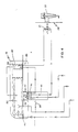
- liquid to be purified is introduced into the novel liquid purification system broadly referred to herein by reference number 2 at system inlet 3 of a suitable chemically-resistant plastic tubing, such as a polyethylene tubing.
- a suitable chemically-resistant plastic tubing such as a polyethylene tubing.
- the liquid to be purified passes along the tubing through an opened solenoid valve 4 through ball control shut-off valve 5 which is maintained in open position during normal liquid purification and treatment cycles into the tapered cylindrical prefilter housing 6 which can be of a suitable chemically-resistant plastic material and which contains a suitable particulate-removing material -- such as a spun polypropylene of a preselected porosity and depth.
- a second tapered cylindrical housing 7 which also is of a suitable chemically-resistant plastic material and which contains a suitable porous bacteriostatic metal alloy material of preselected porosity and depth and which is capable of releasing copper ions into the liquid stream to arrest bacterial growth.
- a commerciallyavailable material such as one referred to as "KDF,” available from the Chemtree Company, can be used along with a suitable and commercially-available granulatar-activated carbon.
- KDF commerciallyavailable material
- the depth and porosity of the material selected can vary depending upon the nature of the liquid to be treated including such parameters as PH level, hardness and turbidity.
- liquid to be purified is introduced into inlet 3 at a volume flow rate of approximately nine hundred (900) to one thousand (1,000) cubic centimeters per minute.
- ball control valve 8 is closed and a small amount of feed liquid in the approximate volume flow rate range of seventy-five (75) cubic centimeters per minute is passed through a restrictor orifice 9 which can be made from any one of a member of suitably-porous materials, such as the commercially-availeble "POREX" material. It is to be noted that a suitable ball-controlled drain valve 10 can be provided before valve 8 to relieve static pressure when desired.
- the liquid to be treated is passed through helically-wound section 11 surrounding a portion of an ultra-violet radiation tube 12 which advantageously can have a wave lenght of two hundred and fifty-four (254) nanometers and be non-ozone producing.
- the liquid then passes through a pup 13 to the feed side of a reverse osmosis unit 14.
- Pump 13 advantageously can be a commercially-available triple diaphrgm, positive displacement pump which serves to minimize pump shear and in turn, temperature increase of the treated liquid during the treatment cycle and to maximize flow rate through the reverse osmosis membrane.
- treated liquid passes through a flow meter 16 and a second conductivity probe 17 for measuring water quality - the first conductivity probe 17 being upstream in "loop cycle" 15 - to a second helically-wound section 18 also surrounding a portion of ultra-violet radiation tube 12.
- the liquid is passed to a unique compartmentalized storage receptacle 19 described in detail hereinafter --which receptacle is capable of heating and/or cooling the liquid to be passed on through a three-way solenoid control 21 to a user tap 22.
- a novel manually operable fluid flow control mechanism can be utilized, in accordance with the present invention for valve 21.
- the reverse osmosis unit 14 can be intermittently treated in "loop cycle" 15 in a manner similar to that described in U.S. Patent No. 4,784,771 and therefore not described in detail herein.
- additional novel features are now included in the "loop cycle” which allows for a straightforward and economical manner of controlling the rate at which the reverse osmosis unit 14 compacts. This is accomplished through two novel restrictor orifices 23 and 24 respectively which, like restrictor orifice 9, can be economically manufactured from any one of a number of suitable porous materials, such as a material sold by the Porex Company, and which is of preselected porosity to allow a preselected variable resistance to liquid flow between restrictive orifices 23 and 24.
- restrictor orifice 23, which is downstream the first conductivity probe 17 in the main line of the loop cycle can be selected to allow a flow volume rate of approximately three (3) liters or three thousand (3,000) cubic centimeters per minute and restrictor orifice 24 in the drain line can be selected to allow a smaller flow volume rate of eight hundred and fifty (850) cubic centimeters per minute with a higher ratio between orifices 23 and 24 generally allowing for a more efficient recovery of product water but of lower quality.
- the new "loop cycle” also includes a suitable pressure relief valve 25 in the drain line to seal against drain flow during the treatment cycle and a unique and novel treatment container arrangement 26 which provides a unitary container for alternative introduction of disinfection/rejuvenation fluids from one of two compartments in the same container -- all in a manner described in detail hereinafter. Also described in detail hereinafter is the flow of fluid through the separate compartments of the compartmentalized storage receptacle 19 ( Figures 1 and 2).
- FIG. 3 of the drawings a modified flow diagram 20 from that of Figure 1 is shown.
- the housing for the ion filter 7 is positioned downstream pump 13 before the reverse osmosis unit and a third helically-wound section 27 is utilized to surround ultra-violet radiation tube 12.
- This third ultra-violet radiation section 27 is utilized to apply a third ultra-violet treatment to the fluid after it leaves storage receptacle 19, returns to a thermoelectric element associated with receptacle 19 and passes to user tap 22.
- the flow of fluid through the separate compartments of the compartmentalized storage receptacle 19 for the embodiment of Figures 3 and 4 is also described hereinafter.
- the inventive housing arrangement for the compact liquid purification system is disclosed as including a walled housing 28, which in the embodiment disclosed advantageously is of rectangular configuration but which can vary in shape in accordance with specific needs.
- Housing 28 serves to provide a main plenum 29 and is preselectively sized to contain liquid purification system 2 therein communicatively extending between inlet 3 which is connected to a water source, to the outlet, which is connected to user tap 22.
- the housing 28 can be formed from any suitably insulated metallic or plastic material and advantageously is formed from a thin but sturdy, light-weight aluminum.
- Drain receptacle 31 which serves to allow evaporation of liquids received thereby, includes vertically extending side wall member 32 which extend normally from the lower peripheral edge thereof.
- the bottom peripheral edge portion of walled housing 28 can be inwardly curved to overlap in spaced relation with the outwardly curved upper edge portion of peripheral side walls 32 of drain receptacle 31. It is to be understood that any one of a number of spacer elements can be utilized to provide the spacing between the inwardly curved lower peripheral edge portions of housing 28 and the outwardly curved upper peripheral edge portions of drain receptacle side walls 32 so as to provide an elongated, air flow dispersing sound baffling passage therebetween.
- the spacer elements can be an integral part of the peripheral side walls 32 of drain receptacle 31 in the form of selectively spaced outwardly extending protuberances 33 abutting and fastened by a suitable fastening device to the otherwise spaced inner face of the curved lower peripheral edge portion of wall housing 28.
- these protrusions 33 could also be formed on the inner face of the inwardly curved edge of walled housing 28 to abut the outer face of peripheral side wall 32.
- plenum 29 serves to slidably receive the side edges of a hereinafter described plate member 34 of liquid storage receptacle 19 which form a part of liquid purification system 2.
- a hereinafter described plate member 34 of liquid storage receptacle 19 which form a part of liquid purification system 2.
- Suitably opposed, mirror-image, longitudinally extending slotted track members 36 of U-shaped cross-section have longitudinally extending bases appropriately mounted in fastened relation to the opposed inner faces of walled housing 28 to receive and support the opposed edges of plate member 34 between the spaced longitudinally extending side portions, as can be particularly seen in Figure 5 of the drawings.
- plate member 34 serves to support from the lower face thereof intermediate opposed track members 36, a thermoelectric module 37 which includes a cold side 38 and a hot side 39.
- the hot side 39 has the heat exchanger or heat sink element 41 suspended therefrom in the form of spaced thermally conductive fin-like plate members.
- plate member 34 can be provided with a slotted gripping handle 42 on the front edge thereof to allow manual slidable movement of the entire storage receptacle assembly 19 on the opposed tracks 36.
- frame member 43 which can be formed from a unitary piece of sturdy sheet metal, such as aluminum or stainless steel, is appropriately sized to extend longitudinally between and spaced from the side walls of housing 28.
- the longitudinal cross-section of frame member 43 is of inverted U-shape to provide a base panel 44 and two spaced side panels 46 and 47.
- base panel 44 When properly inserted in the lower portion of plenum 29, base panel 44 extends in a horizontal plane and the spaced front and rear side panels or legs 46 and 47 respectively extend downwardly with the corner extremity of each side panel having a footing 48 which rests on the upper face of drain receptacle 31.
- footing 48 which rests on the upper face of drain receptacle 31.
- the lower face portion of drain receptacle 31 also is provided with similar footings 49 at the corners thereof so that the entire housing 28, including drain receptacle 31 and independently resting frame member 43 disposed thereon can rest on a flat support surface, such as a table top.
- the parallel front and rear side panels 46 and 47 respectively are provided with spaced, aligned apertures which are appropriately sized to receive therethrough in snug nestingly wedge-like engagement therewith in a lower tier the inwardly tapered filter housings 6 and 7.
- the front ends of spaced parallel, tapered filter housings 6 and 7 are connected by a slotted connecting panel member 51 to allow ready removal of both tapered housings 6 and 7 from frame member 43.
- suitable gaskets 52 which can be of plastic, are provided around the peripheries of the aligned apertures to insure firm wedging of the tapered filter housings 6 and 7 therein.
- diaphragm pump 13 suspended in the lower tier from the underside of horizontal base panel in spaced relation between frame supported filter housings 6 and 7 is diaphragm pump 13 and mounted in an upper tier on the upper face of horizontal base panel 44 in spaced relation from either side of the heat exchange fins 41 is the reverse osmosis unit 14 and a power pack 53.
- This power pack 53 which includes an appropriate transformer and voltage regulator serves to provide a selected level of electrical energy (12 volts) to several parts of liquid purification system 2 requiring such energy and which are disposed in plenum 29, including but not limited to the thermoelectric module 37 and blower 56 ( Figure 6) which moves ambient air from inlet 20 in walled housing 28 over heat exchange fins 41 to which the blower is attached and downwardly through the aforedescribed outlet passage defined between the spaced walls of walled housing 28 and drain pan 31.
- the ultra-violet radiation tube 12, the pump 13 and the heater plate 54 in storage receptacle 19 can be supplied with electrical energy from a direct separate appropriate energy source, such as a 220 volt source.
- ultra-violet tube 12 can be vertically positioned on the inside face of the front cover adjacent the novel treatment container arrangement 26, tube 12 further serving to light the front panel, a portion of which can be in the form of a transparent polycarbonate window to block ultra-violet radiation from tube 12.
- tube 12 and the conduit sections therearound can, in turn, be surrounded with a radiation absorption and reflective shield (not shown) which, advantageously, can be in the form of a suitable number of layers of aluminized coated sheets of Mylar material which serve to absorb the emitted radiation from tube 12 and to reflect a portion thereof back to the surrounding coil sections.
- a radiation absorption and reflective shield (not shown) which, advantageously, can be in the form of a suitable number of layers of aluminized coated sheets of Mylar material which serve to absorb the emitted radiation from tube 12 and to reflect a portion thereof back to the surrounding coil sections.
- This treatment container 26 can be unitary in form and is fluid impervious to provide two fluid impervious compartments 57 and 58 for introduction of disinfection and rejuvenation fluids respectively for treatment of the reverse osmosis unit 14.
- appropriately selected acid and base fluids are respectively provided, one of the two fluids being stored in each compartment.
- a compartment header block 59 is mounted in sealed relation at corresponding fluid communication ends for each of the compartments 57 and 58, this unitary header block 59 serving to provide a header pair, one for each compartment 57 and 58.
- the header for each compartment or in other words the header pair, is formed from the single unitary header block 59.
- Each compartment header of the header pair in unitary header block 59 is provided with a spaced set of three mating port connections 61, 62, 63 which are embedded in unitary header block 59 in mirror-image relation, as can be seen in Figure 12.
- each port connection of each set can, when treatment container 26 is properly positioned, communicate with the respective compartments 57, 58 thereabove.
- the lower end of each port connection is of a female nature and when a respective compartment 57, 58 is in operating position, receive a male nipple of connections 64, 66, 67 embeddedly mounted in the treatment header block 68.
- the lower female ends of connections 61, 62 and 63 of a connection set for a compartment connect respectively with the nipples of connections 64, 66, 67 in a connecting arrangement of 61-64, 62-66 and 63-67.
- treatment header block 68 to which compartment header block 59 is connected can be positioned in drain receptacle 31.
- a tie-down connection in the form of a nipple 69 is provided in treatment header block 68.
- This tie-down connection 69 serves to engage with the female portion of connection 61 of that set of mirror-image connections 61, 62, 63 of a compartment 57 or 58 which is not in operating position.
- a suitable spring loaded latch 71 such as a quick disconnect latch sold by Colder Products of Minneapolis, Minnesota, cooperatively associated with tie-down nipple or connection 69, serves to yieldingly hold the tie-down connection 69 in engagement with the female portion of connection 61 of that mirror-image set of connections not in operating position.
- compartment header block 59 By merely rotating compartment header block 59 through one hundred eighty degrees (180°), one of the two disinfection/rejuvenation compartments 57 and 58 can be connected to the treatment header block 68 which comprises part of liquid purification system 2, with the other compartment not operatively connected being appropriately anchored on nipple 69 by spring loaded latch 71.
- an appropriate manual access recess 72 can be provided adjacent female connection 61 on either side of compartment header block 59.
- the fluid impervious disinfection/rejuvenation compartments 57 and 58 can be formed from three vacuum molded thin, light rigid panels formed from a suitable fluid impervious material, such as an appropriate polycarbonate compound, which material also can be used to form the compartment header manifold 59 and the treatment header block 68 above described.
- a suitable fluid impervious material such as an appropriate polycarbonate compound, which material also can be used to form the compartment header manifold 59 and the treatment header block 68 above described.
- Two of the three panels forming fluid impervious compartments 57 and 58, namely outside panels 73 and 74 are identically sized and flanged along three edges -- namely, the two opposed side edges and the base edge from which the side edges extend.
- These three flange edges of the two outside panels 73 and 74 are positioned in mirror-image facing relation to initially provide a chamber of longitudinally extending rectangular configuration form to include an open mouth header inlet end adjacent and fastened to the header block 59, which provides, as a unit, the aforedescribed compartment headers for each compartment 57 and 58.
- the bases of the flanged opposed panels provide the closed end of the compartments 57 and 58.
- a third panel 76 interposed between mirror-image edge flanged panels 73 and 74 serves as a divider wall therebetween to provide fluid impervious compartments 57 and 58.
- Panel 76 can be in the form of a longitudinally-extending wave-shaped sheet to extend longitudinally between the mirror-image positioned first and second outside panels 73 and 74 from the open-mouth header inlet end to the opposed closed end and from diametrically-opposed corners of the longitudinally-extending chamber of rectangular configuration formed by outside panels 73 and 74 with the longitudinally-extending opposed side and base edges of all three panels -- namely outside panels 73 and 74 and divider panel 76 having a common seam 75 which extends along the opposed side and base edges thereof to provide the pair of compartments 57 and 58 in mirror-image nesting relation.
- These compartments 57 and 58 are geometrically of triangular-like cross-sectional configuration to extend from the header ends to the closed end.
- header block 59 is provided with a suitably recessed surrounding peripheral edge 77 and a wave-like recess 78 extending centrally between the opposed sides of the peripheral recessed edge 77 to overlappingly receive and respectively nest with the joined header edges of the three panels 73, 74 and 76.
- each inlet connection 62 and disposed within compartments 57 and 58 are pressure sensing valves 79 and 81 which are utilized within each compartment to regulate flow during the treatment cycle, to determine compartment fill and, in an emergency, to shut off fluid flow to the compartment at a preselected volume level.
- thermoelectric module 37 is positioned adjacent cold storage compartment 83 so as to cool the fluid introduced into cold storage bag member 82.
- cold storage bag member 82 and hot storage bag member 87 can be formed from sheets of a thin, thermally-conductive material, such as Mylar.
- the hot storage compartment 88 is provided in the floor thereof with a suitable foil strip heater 89 such as one sold by Minco of Minneapolis, Minnesota.
- this foil strip heater 89 can be wrapped or otherwise protected with an insulating material such as a closed cell silicone foam which insulator serves to modulate the temperature to fall within a range of approximately 250°F to 300°F.
- a suitable over temperature regulator (not shown) can be provided to interrupt a 220 volt energy supply to the foil heater from the same supply source supplying energy to ultra-violet radiation tube 12.
- a portion of the heated fluid in hot storage bay member 87 is caused to vaporize by the temperatures imparted thereto, thus reducing bacterial contaminants with the thus vaporized and bacterial treated vapors flowing over from hot storage bag 87 to cold storage bag 82.
- These vapors condense in cold storage bag 82 with the fluid level rising in the bag and the aforedescribed cycle of fluid flow is repeated. If it is desired to obtain hot fluid at user tap 22, it is only necessary to adjust three port or three-way valve accordingly, shutting off cold fluid flow from cold storage bag 82 thereto and turning on hot fluid flow from hot storage bag 87.
- the path of fluid flow is, in many respects, similar to that aforedescribed.
- the cold fluid from cold storage bag 82 is passed to helical coil section 27, also surrounding ultra-violet radiation tube 12 for a third ultra-violet radiation treatment. From there, the fluid passes through the cold side 38 of thermoelectric module 37 and then to user,tap 22 through flow control 21.
- appropriate control valving such as at 21 can be employed to allow alternative hot and cold fluid flow to user tap 22 and, if desired and as shown, appropriate heating foil and vaporization circuitry between bags 82 and 87 can be utilized.
- Switch member 91 is disclosed as associated with the cover 92 for storage receptacle 19.
- Cover 92 like storage receptacle 19 of which it is a part and accordingly-sized and shaped to engage the lower portion thereof, can be formed from a suitable, insulated foam polyurethane material in a manner comparable to the novel method disclosed in Figure 28 and described hereinafter.
- Cover member 92 is formed with a lower recess 93 in which three magnetically-actuable contact switches 94 are embedded in a common horizontal plane at approximately 120° to each other in a common circle, these switches being included in parallel in an appropriate electrical circuit (not shown) which controls fluid flow to bag members 82 and 87.
- a Mylar sheet 96 is fastened to the lower face of cover 92, this sheet being sized to cover recess 93.
- Supported within recess 93 by sheet 96 is a second sheet 97, which sheet determines a common plane and on which are mounted three magnets 98 which like switches 94 are arranged to fall within a common circle, one hundred and twenty degrees (120°) apart to determine a common plane and to be aligned with contact switches 94.
- sheet 97 can be of a rigid, polycarbonate material or any other suitable material having low magnetic and thermal conductivity. Accordingly, when any part of storage bag 82 in compartment 83 of storage receptacle 19 reaches a certain preselected level it moves one of magnets 98 supported on sheet 97 toward an aligned contact switch 94 and causes fluid flow to cold and hot storage bags 82 and 87 to be interrupted. It is to be noted that suitable vent lines 90 are provided in cover 92 to allow ambient communication with compartments 83 and 88 and recess 93.
- Plate member 34 which is embedded in the lower portion of storage receptacle 19 is disclosed.
- Plate member 34 which advantageously can be formed from a thin, stiff metallic sheet desirably of preselected thermal conductivity, such as aluminum, extends in a flat plane through the lower portion of polyurethane storage receptacle 19
- Plate 34 is provided with selectively-sized and positioned passages therein in the form of spaced lineal aligned flow-through circular holes 99 and spaced lineal-aligned slots 101 which are arranged geometrically to define two rectangular forms which serve to provide the geometric wall limitations for cold and hot storage compartments 83 and 88 above discussed, all in accordance with a novel forming method described hereinafter.
- these spaced circular and lineal passages 99 and 101 serve to further define tortuous pathways therebetween to reduce thermal conductivity through the plate from one formed compartment 83 to the other formed compartment 88 with the spacing between holes 99 and slots 101 also allowing for a certain amount of flexibility relative the respective cold and hot storage receptacle walls formed on one face of the plate and between the walls and the bottom of the receptacle formed on the other face of the plate in a manner described hereinafter.
- bag members 82 and 87 are shown as part of the same unit bay assembly 105 formed and geometrically-contoured and sized from two appropriately-sized and shaped sheets or plackets 102 and 103 of thin flexible material, such as Mylar, which are cut and fuse-joined in facing mirror-image form along a common seam 104 to provide pockets forming bag members 82 and 87 which are communicatively joined along a cut and shaped common passage 106 extending between the pockets forming bag members 82 and 87.
- FIG. 23-26 of the drawings details are disclosed of a novel by-pass check valve 86 which can be associated with fluid storage receptacle 19 when employed in a liquid purification system such as is set forth in Figures 1 and 2 of the drawings.
- This novel check valve 86 is extremely straightforward and economical in construction, assembly and maintenance yet efficiently accomplishes the purposes for which it is intended.
- it simply comprises a break and spacing in the vertically-extending portion of silicone by-pass conduit line associated with storage receptacle 19 which line extends between cold storage bag 82 and the hot storage bag 87 passing through the hot side 39 of thermoelectric module 37, as previously described.
- FIG. 23-25 This break and spacing of the by-pass line is illustrated in Figures 23-25 and for purposes of description is referred to as spaced and aligned lines 107 and 108.
- the ends of lines 107 and 108 are surrounded by a tubing sleeve 109 of appropriate length with an inner diameter which approximates the outer diameter of the by-pass lines 107 and 108.
- the tubing sleeve 109 which advantageously can also be of silicone material, can be held in fast position by a suitable ambient hardening silicone adhesive paste to define a float chamber 111 between the broken and spaced vertically-extending by-pass line.
- a float member 112 Positioned within chamber 111 is a float member 112, which, as shown, can be in the form of a ball.
- Float 112 is of a preselected specific gravity slightly lower than the specific gravity of the liquid to be stored in storage receptacle 19.
- float 112 can have a specific gravity of 0.91 when the liquid to be stored is water.
- Float 112 is appropriately-sized to float and cover the inner diameter of line 107 of the vertically-extending by-pass line when the differential pressure between bag members 82 and 87 is at a preselected lower level ( Figures 24).
- Figures 24 When the differential pressure between bag members 82 and 87 increases, it forces float 112 downwardly away from the extremity of line 107 to open line 107 to fluid flow, the float being urged by the difference in pressure toward spaced and aligned line 108.
- the extremity of aligned line 108 spaced and opposed to the extremity of line 107 is so shaped that float 112 can nest but not cover the opening of this extremity.
- the extremity of line 108 can be of triangular apex shape as at 113 with a counter groove 114 centrally disposed at apex 113 sized in breadth to receive float 112 in nesting seated relation therewith but sized in depth to prevent the nesting, seated float 112 from covering the opening of line 108 so as to allow fluid to continue to pass therethrough from opened, aligned and spaced line 107 and the chamber 111.
- housing 28 is disclosed with the front wall thereof, herein referred to as front wall 128, shown as being shaped to include a user tap recess 129 therein to receive the aforedescribed user tap 22 which can be any one of a number of commercially-available spigots, such as the one disclosed and commercially available from Tomlinson Company.
- This user tap spigot 22 conveniently is designed to receive and support a glass at a location below the spigot spout to pour fluid into the glass by applying a nominal hand pressure on the spigot-supported glass.
- the upper portion of the front wall 128 of housing 28, which front wall extends the height of the housing, is provided with a pair of generally U-shaped over-center pivotal hinges 131.
- One leg extremity 132 of each hinge 131 (only one being shown) is shown as pivotally-mounted to the side wall of housing 28 with the opposite leg extremity 133 being fastened to the upper portion of the curved side of front wall 128.
- over-center hinges 131 are so designed as to permit the front cover to be pivoted through approximately one hundred and thirty degrees (130°) to a position above the top wall portion of housing 28.
- the over-center hinges 131 can be designed to allow other pivotal situations, if so desired.
- mold structure for the unique formation of the lower portion of aforedescribed storage receptacle 19 is disclosed.
- This structure includes a pair of mating upper and lower mold halves 134 and 136 respectively which are internally contoured to provide the bottom wall of the lower portion of storage receptacle 19 and the peripheral and intermediate side walls extending from the bottom wall to appropriately define the aforedescribed fluid compartments 83 and 88 of storage receptacle 19 which receive the cold and hot storage bags 82 and 87, respectively.
- the upper and lower mold halves 134 and 136 are closed in mating relation along opposite faces of aforedescribed plate member 34.
- a suitable plastic material such as a closed cell foam polyurethane along with an appropriate catalyst is then introduced under pressure from a storage source not shown through lower mold inlet 137.
- the foam polyurethane selected can have appropriately high heat resisting and insulating qualities which are required for the varying temperatures realized in cold and hot storage compartments 83 and 88 respectively.
- the foam polyurethane introduced into lower mold half 136 is in sufficient quantity and under sufficient pressure to pass through the holes 99 and lineal slots 101 which are aligned with appropriately-designed recesses to provide the bottom or base wall and the connected or integral peripheral side and intermediate walls of storage receptacle 19 as above described.
- a longitudinally-extending compartment header block 59 is formed from a suitable plastic material such as polycarbonate to include the aforedescribed fluid outlet and inlets and air connections 61, 62 and 63 for each separate fluid compartment 57 and 58.
- the header block is shaped to include an upper peripheral recessed edge 77 and a wave-like recess 78 extending centrally along the upper face of the block between the opposed longitudinal sides thereof.
- Mirror-image outside panels 73 and 74 and a compartment dividing wave-like intermediate panel 76 are mold formed with the panels being so configured and sized that the outside panels 73 and 74 provide a rectangular-shaped chamber therebetween which subsequently is divided into two compartments 57 and 58 with the opposed side and bottom edges of the two outside panels 73 and 74 and the intermediate panel 76 in facing relation with each other to be fuse joined in open-ended two compartment relation.
- the open-ended edges of the outside panels 73 and 74 and the end portions of intermediate panel 76 are positioned to surround and be sealed to the peripherally surrounding recessed edge 77 of block 59 with the intermediate edge of wave-like intermediate panel 76 nestingly engaging and being sealed to the wave-like recess 78 in header block 59.
- two similarly-shaped sheets 102 and 103 of fluid impervious material, such as Mylar, are each sized, shaped and cut as identical plackets to provide bag sides 82 and 87 with a side of a connecting portion 106 therebetween.
- the plackets are then placed in mirror-image relation and sealed completely along the edges thereof as at 104 so as to provide bags 82 and 87 joined by connecting passage 106 extending therebetween.
- a novel fluid flow control mechanism 143 for flexible conduits 141 and 142 which can be used in place of solenoid 21.
- These conduits 141 and 142 are used to alternately connect cold storage bag member 82 and hot storage bag member 87 respectively and which are located in storage receptacle 19 to user tap 22.
- These conduits 141 and 142 are advantageously made of a long-wearing, flexible silicone material inherently capable of emitting a microscopically detectable silicone lubricant when flexed.
- the conduits are of a preselected thickness in accordance with desired fluid flow capacity from the respective storage bag members 82 and 87 to which they are connected and lead to a liquid outlet and user tap 22 through an appropriate Y-connection (not shown), each passing through the novel fluid flow control mechanism 143 which serves to deliver fluid from each of said storage bag members 82 and 87 alternatively to user tap 22.
- This liquid control mechanism 143 is comprised of a pair of relatively slidable, superposed plates 144 and 146 which can be mounted appropriately on one of the walls of walled housing 28 with a manual gripping handle 167 mounted on pin 151 projecting through the mounted wall to provide relative slidable movement between plates 144 and 146.
- teflon washers 147 can be provided between plates 144 and 146 to space the plates and to enhance relative slidable movement therebetween.
- Base plate 144 which can be provided at diametrically opposed corners with slots 148 to allow relative movement of this base plate on the wall to which it is mounted, can be of elongated rectangular shape of a preselected length.
- Superposed plate 146 can be of a shorter length than base plate 144 and can be of S-shape with a width substantially equal to base plate 144.
- These plates 144 and 146 can be made from a suitable light, sturdy, metallic material.
- a suitable elongated guide slot 149 is provided in base plate 144 midway between the sides thereof with pin 151 having gripping handle 167 fastened on superposed plate 146 slidably projecting therein.
- Spaced, elongated guide slots 153 and 154 are aligned with each other on superposed plate 146 and with guide slot 149 on base plate 144.
- Pins 156 and 157 mounted on base plate 144 project through guide slots 153 and 154 on plate 146 respectively to permit relative slidable movement therebetween.
- a pair of conduit receiving rings 158 and 159 and a pair of conduit receiving rings 161 and 162 are mounted in staggered positions on each plate 144 and 146 with the rings on corresponding sides of relatively slidable plates 144 and 146 being aligned and so positioned that when the aligned rings 162 and 159 on corresponding sides of the two relatively slidable plates are proximate to each other, then the aligned rings 158 and 161 on the other corresponding sides of the two relatively-slidable plates are remote from each other.
- These aligned rings are so sized that each pair on corresponding sides has one of the two conduits 141 and 142 passing therethrough.
- a pair of gripping sleeves 163 and 164 which can also be of suitable silicone tubing material, are sized to snugly engage the outer peripheries of conduits 141 and 142, and are fastened to the outer peripheries on opposite sides of each ring.
- each conduit can be properly gripped in a preselectively flexed minimum arc position to be in open position and a preselectively flexed maximum arc position to be in closed position with the open and closed position alternating for each conduit as can be seen in Figures 29 and 30 and Figures 31 and 32.
- This serves to allow alternative flow of fluids from storage bag members 82 and 87 in storage receptacle 19.
- a suitable helical spring 166 can be arranged to be fastened at one end thereof to actuating pin 151 which pin can be extended, as above described, and can be arranged to project through a wall of the walled housing 28 with a gripping handle 167 fastened thereto.
- the other end of spring 166 is fastened to pin 157 extending through slot 154 on the superposed plate 146.
- This helical spring 166 serves to spring bias the relative movement between plates 144 and 146 so that when conduit 142, which in the embodiment illustrated is connected to hot storage bag member 87 is urged to fully open position as shown in Figures 29 and 30, the urging force is against the resistance of the spring biasing means 166.
- each of the silicone conduits also serves to urge each conduit to its selected destined position.
- the conduit material selected should have long-lasting flexing qualities and be of appropriate thickness and characteristics to seal from the center of the axial line of fluid flow through the conduit to the inner peripheral sides thereof.
- the selection of the flexed arc positions of each conduit need not be from an alternative minimum arc, fully-open to a maximum arc, fully-closed position but that in other situations, it would be possible to control the flow somewhere in between these two positions.
Landscapes
- Chemical & Material Sciences (AREA)
- Engineering & Computer Science (AREA)
- Water Supply & Treatment (AREA)
- Chemical Kinetics & Catalysis (AREA)
- Organic Chemistry (AREA)
- Environmental & Geological Engineering (AREA)
- Hydrology & Water Resources (AREA)
- Life Sciences & Earth Sciences (AREA)
- Nanotechnology (AREA)
- Health & Medical Sciences (AREA)
- Clinical Laboratory Science (AREA)
- Toxicology (AREA)
- Separation Using Semi-Permeable Membranes (AREA)
- Physical Water Treatments (AREA)
- Check Valves (AREA)
- Heat Treatment Of Water, Waste Water Or Sewage (AREA)
Applications Claiming Priority (2)
| Application Number | Priority Date | Filing Date | Title |
|---|---|---|---|
| US515459 | 1990-04-27 | ||
| US07/515,459 US5017284A (en) | 1990-04-27 | 1990-04-27 | Fluid purifying apparatus and method of purifying fluids |
Publications (1)
| Publication Number | Publication Date |
|---|---|
| EP0454614A1 true EP0454614A1 (fr) | 1991-10-30 |
Family
ID=24051434
Family Applications (1)
| Application Number | Title | Priority Date | Filing Date |
|---|---|---|---|
| EP91630009A Withdrawn EP0454614A1 (fr) | 1990-04-27 | 1991-01-31 | Appareil pour purifier des fluides et méthode pour purifier des fluides |
Country Status (7)
| Country | Link |
|---|---|
| US (1) | US5017284A (fr) |
| EP (1) | EP0454614A1 (fr) |
| JP (1) | JPH06292886A (fr) |
| KR (1) | KR910018061A (fr) |
| CN (1) | CN1055910A (fr) |
| BR (1) | BR9101230A (fr) |
| CA (1) | CA2036801A1 (fr) |
Cited By (1)
| Publication number | Priority date | Publication date | Assignee | Title |
|---|---|---|---|---|
| US7794592B2 (en) | 2006-06-29 | 2010-09-14 | Ralph Brown | Wastewater disinfection apparatus and methods |
Families Citing this family (46)
| Publication number | Priority date | Publication date | Assignee | Title |
|---|---|---|---|---|
| US5174121A (en) * | 1991-09-19 | 1992-12-29 | Environmental Water Technology | Purified liquid storage receptacle and a heat transfer assembly and method of heat transfer |
| US5269919A (en) * | 1992-01-17 | 1993-12-14 | Von Medlin Wallace | Self-contained water treatment system |
| US5536395A (en) * | 1993-03-22 | 1996-07-16 | Amway Corporation | Home water purification system with automatic disconnecting of radiant energy source |
| US5381742A (en) * | 1993-09-17 | 1995-01-17 | Landa, Inc. | Waste liquid evaporator |
| US5573142A (en) * | 1994-10-17 | 1996-11-12 | Whirlpool Corporation | Bottled water dispensing cabinet |
| US5858248A (en) * | 1995-03-31 | 1999-01-12 | The Coca-Cola Company | On premise water treatment method for use in a post-mix beverage dispenser |
| US5776333A (en) * | 1995-03-31 | 1998-07-07 | The Coca-Cola Company | On premise water treatment apparatus |
| KR0175908B1 (ko) * | 1996-05-25 | 1999-03-20 | 김광호 | 냉온정수기의 램프제어장치 및 그 방법 |
| TW315754U (en) * | 1997-03-13 | 1997-09-11 | En Yie Water System Inc | Table type reverse osmosis water dispenser structure |
| US6074551A (en) * | 1998-04-30 | 2000-06-13 | Culligan Water Conditioning Of Fairfield County | Automatic cleaning system for a reverse osmosis unit in a high purity water treatment system |
| US6264830B1 (en) | 1999-08-13 | 2001-07-24 | The Coca-Cola Company | On premise water treatment system and method |
| US6495049B1 (en) | 1999-10-21 | 2002-12-17 | The Coca-Cola Company | On premise water treatment system with temperature control water release and method |
| US6610210B2 (en) | 2001-06-22 | 2003-08-26 | The Coca-Cola Company | Disposable cartridge for on-premises water treatment system |
| CN1325386C (zh) * | 2002-05-07 | 2007-07-11 | 可口可乐公司 | 具有包括加热元件的盛装已处理水的容器的自动消毒水处理设备 |
| US20040055946A1 (en) * | 2002-09-20 | 2004-03-25 | Sid Harvey Industries, Inc. | Dual filtration system |
| US7001524B2 (en) * | 2003-06-02 | 2006-02-21 | Steven Clay Moore | Method for removing scale causing chemicals in hot water systems |
| WO2006055870A1 (fr) * | 2004-11-21 | 2006-05-26 | David Mitchell Windmiller | Bouteilles remplissables par le fond et systemes de remplissage desdites bouteilles |
| US7534349B2 (en) * | 2005-09-02 | 2009-05-19 | Nephros, Inc. | Dual stage ultrafilter devices in the form of portable filter devices, shower devices, and hydration packs |
| US8152995B2 (en) * | 2005-10-14 | 2012-04-10 | Steven Clay Moore | Arrangements to reduce hardness of water in a hot water system |
| US7955476B2 (en) * | 2006-01-20 | 2011-06-07 | Mansur Corporation | Multiple application purification and recycling device |
| US11261116B2 (en) * | 2009-10-09 | 2022-03-01 | John James McEncroe | Fluid treatment system |
| KR101210704B1 (ko) | 2010-03-19 | 2012-12-10 | 씨제이제일제당 (주) | 5'-크산틸산 및 5'-구아닐산 생산능이 향상된 미생물 및 이를 이용한 5'-크산틸산 또는 5'-구아닐산의 생산방법 |
| CN101843910B (zh) * | 2010-05-05 | 2013-01-09 | 贾平 | 循环流化床紫外灭菌机及其用于粉体物料的紫外灭菌方法 |
| US9776899B2 (en) * | 2012-05-16 | 2017-10-03 | Jon-Andrew Vincent Sigona | Full contact UV water purification system |
| EP2882691A4 (fr) | 2012-08-10 | 2016-02-10 | Xylem Water Solutions Zelienople Llc | Procédé et appareil de surveillance et de régulation de l'ozonation et de la filtration aérée au moyen de mesures dans les spectres uv et visible et du potentiel d'oxydation-réduction |
| KR101548911B1 (ko) * | 2013-06-14 | 2015-09-01 | 문성수 | 수압을 이용한 정수장치 |
| KR102149257B1 (ko) * | 2013-07-30 | 2020-08-28 | 서울바이오시스 주식회사 | 자외선 발광 다이오드를 갖는 정수기 |
| US10392269B2 (en) * | 2013-10-09 | 2019-08-27 | Kevin E. Munro | Portable water purification systems with adjustable solar positioning apparatus |
| US10207936B2 (en) | 2016-02-19 | 2019-02-19 | Silanna UV Technologies Pte Ltd | Ultraviolet reactor with planar light source |
| US20170259211A1 (en) * | 2016-03-11 | 2017-09-14 | Ching Hsiung LIN | Reverse osmosis filtration system without pressure tanks |
| AU2017330537A1 (en) | 2016-09-20 | 2019-04-11 | Aqua Membranes Llc | Permeate flow patterns |
| WO2018094288A2 (fr) | 2016-11-19 | 2018-05-24 | Aqua Membranes Llc | Dispositifs d'orientation de flux pour éléments enroulés en spirale |
| KR102551387B1 (ko) | 2017-04-12 | 2023-07-04 | 아쿠아 멤브레인스 인코포레이티드 | 여과 권취 요소를 위한 단계적 스페이서 |
| KR102355893B1 (ko) | 2017-04-20 | 2022-01-26 | 아쿠아 멤브레인스 인코포레이티드 | 나선형 권취 요소를 위한 비-중첩, 비-변형 패턴 |
| US11745143B2 (en) | 2017-04-20 | 2023-09-05 | Aqua Membranes, Inc. | Mixing-promoting spacer patterns for spiral-wound elements |
| WO2019075370A1 (fr) | 2017-10-13 | 2019-04-18 | Aqua Membranes Llc | Support de pont et entretoises d'alimentation réduites pour des éléments enroulés en spirale |
| CN110374169A (zh) * | 2018-04-12 | 2019-10-25 | 佛山市顺德区美的饮水机制造有限公司 | 水袋、压力罐及净水器 |
| HU5090U (hu) * | 2018-05-11 | 2019-11-28 | Evolutionwater Kft | Eszköz fluidumok mágneses kezelésére |
| DE102018112362A1 (de) * | 2018-05-23 | 2019-11-28 | Grohe Ag | Vorrichtung und Verfahren zur Reinigung einer Trinkwasseraufbereitungsanlage |
| CN110186246A (zh) * | 2019-07-04 | 2019-08-30 | 长虹美菱股份有限公司 | 一种用于冰箱的增香净味装置及其控制方法 |
| CN110748901B (zh) * | 2019-11-04 | 2022-05-27 | 洪新思 | 一种高温催化污水处理装置及高温催化污水处理工艺 |
| US11633700B2 (en) | 2020-04-07 | 2023-04-25 | Aqua Membranes Inc. | Independent spacers and methods |
| CN112432511B (zh) * | 2020-11-16 | 2024-02-20 | 无锡晶瑜智能机械有限公司 | 一种具有废气处理功能的环保式工业炉窑 |
| CN113003653B (zh) * | 2021-03-16 | 2023-04-11 | 重庆四联光电科技有限公司 | 过流式水杀菌装置 |
| US11859858B1 (en) | 2022-02-02 | 2024-01-02 | Terry Zarling | Copper coated AC drain pan basin |
| CN115554857A (zh) * | 2022-12-05 | 2023-01-03 | 清华大学 | 一种基于臭氧超微气泡的陶瓷膜阻垢系统及方法 |
Citations (10)
| Publication number | Priority date | Publication date | Assignee | Title |
|---|---|---|---|---|
| US3089513A (en) * | 1960-12-01 | 1963-05-14 | Jr Chester Howard Kirk | Combination fill valve and expansion tank |
| US3726793A (en) * | 1971-05-03 | 1973-04-10 | Desalination Systems | Reverse osmosis water purifying system with gradient barrier water storage container |
| FR2309238A1 (fr) * | 1975-05-02 | 1976-11-26 | Gow James | Procede et appareil pour produire des solutions aqueuses a usage medical |
| GB1474602A (en) * | 1974-05-07 | 1977-05-25 | Grumman Allied Industries | Storage of metabolically active material |
| US4160727A (en) * | 1976-02-21 | 1979-07-10 | Foremost-Mckesson, Inc. | Method and apparatus utilizing staged reverse osmosis units for purifying and dispensing water |
| US4604194A (en) * | 1984-12-04 | 1986-08-05 | Entingh Melvin E | Water conditioner valve and system |
| US4752389A (en) * | 1987-03-30 | 1988-06-21 | Burrows Bruce D | Water purification system with purified water cooling apparatus |
| US4769131A (en) * | 1986-05-09 | 1988-09-06 | Pure Water Technologies | Ultraviolet radiation purification system |
| CH667866A5 (de) * | 1985-09-25 | 1988-11-15 | Ciba Geigy Ag | Verfahren und vorrichtung zum aufbereiten von wasser. |
| US4969991A (en) * | 1989-08-30 | 1990-11-13 | Valadez Gerardo M | Water purifying and dispensing system |
Family Cites Families (1)
| Publication number | Priority date | Publication date | Assignee | Title |
|---|---|---|---|---|
| US4784771A (en) * | 1987-08-03 | 1988-11-15 | Environmental Water Technology, Inc. | Method and apparatus for purifying fluids |
-
1990
- 1990-04-27 US US07/515,459 patent/US5017284A/en not_active Expired - Fee Related
-
1991
- 1991-01-31 EP EP91630009A patent/EP0454614A1/fr not_active Withdrawn
- 1991-02-21 CA CA002036801A patent/CA2036801A1/fr not_active Abandoned
- 1991-03-12 CN CN91101594A patent/CN1055910A/zh active Pending
- 1991-03-15 KR KR1019910004125A patent/KR910018061A/ko not_active Application Discontinuation
- 1991-03-23 JP JP3083610A patent/JPH06292886A/ja active Pending
- 1991-03-27 BR BR919101230A patent/BR9101230A/pt unknown
Patent Citations (10)
| Publication number | Priority date | Publication date | Assignee | Title |
|---|---|---|---|---|
| US3089513A (en) * | 1960-12-01 | 1963-05-14 | Jr Chester Howard Kirk | Combination fill valve and expansion tank |
| US3726793A (en) * | 1971-05-03 | 1973-04-10 | Desalination Systems | Reverse osmosis water purifying system with gradient barrier water storage container |
| GB1474602A (en) * | 1974-05-07 | 1977-05-25 | Grumman Allied Industries | Storage of metabolically active material |
| FR2309238A1 (fr) * | 1975-05-02 | 1976-11-26 | Gow James | Procede et appareil pour produire des solutions aqueuses a usage medical |
| US4160727A (en) * | 1976-02-21 | 1979-07-10 | Foremost-Mckesson, Inc. | Method and apparatus utilizing staged reverse osmosis units for purifying and dispensing water |
| US4604194A (en) * | 1984-12-04 | 1986-08-05 | Entingh Melvin E | Water conditioner valve and system |
| CH667866A5 (de) * | 1985-09-25 | 1988-11-15 | Ciba Geigy Ag | Verfahren und vorrichtung zum aufbereiten von wasser. |
| US4769131A (en) * | 1986-05-09 | 1988-09-06 | Pure Water Technologies | Ultraviolet radiation purification system |
| US4752389A (en) * | 1987-03-30 | 1988-06-21 | Burrows Bruce D | Water purification system with purified water cooling apparatus |
| US4969991A (en) * | 1989-08-30 | 1990-11-13 | Valadez Gerardo M | Water purifying and dispensing system |
Cited By (1)
| Publication number | Priority date | Publication date | Assignee | Title |
|---|---|---|---|---|
| US7794592B2 (en) | 2006-06-29 | 2010-09-14 | Ralph Brown | Wastewater disinfection apparatus and methods |
Also Published As
| Publication number | Publication date |
|---|---|
| CA2036801A1 (fr) | 1991-10-28 |
| KR910018061A (ko) | 1991-11-30 |
| BR9101230A (pt) | 1991-11-26 |
| US5017284A (en) | 1991-05-21 |
| CN1055910A (zh) | 1991-11-06 |
| JPH06292886A (ja) | 1994-10-21 |
Similar Documents
| Publication | Publication Date | Title |
|---|---|---|
| US5017284A (en) | Fluid purifying apparatus and method of purifying fluids | |
| US5043066A (en) | Fluid purifying apparatus and method of purifying fluids | |
| US5484538A (en) | Multiple service water purifier and dispenser and process of purifying water | |
| US5053143A (en) | Fluid purifying apparatus and method of purifying fluids | |
| AU2005282371B2 (en) | Water producing method and apparatus | |
| US6058718A (en) | Portable, potable water recovery and dispensing apparatus | |
| EP0891523B1 (fr) | Dispositif portable de recuperation d'eau potable et de distribution | |
| CA2341106C (fr) | Appareil portable de recuperation et de distribution d'eau potable | |
| US6370884B1 (en) | Thermoelectric fluid cooling cartridge | |
| US6101835A (en) | Water and ice dispensing apparatus | |
| CA2251095C (fr) | Dispositif portable de recuperation d'eau potable et de distribution | |
| US5076913A (en) | Fluid purifying apparatus and method of purifying fluids | |
| CN113056317B (zh) | 水蒸馏设备、方法和系统 | |
| US5039411A (en) | Fluid purifying apparatus and method of purifying fluids | |
| US5094743A (en) | Fluid purifying apparatus and method of purifying fluids | |
| US5065791A (en) | Fluid purifying apparatus and method of purifying fluids | |
| US5069785A (en) | Fluid purifying apparatus and method of purifying fluids | |
| US5071548A (en) | Fluid purifying apparatus and method of purifying fluids | |
| JP2003072896A (ja) | 飲料用温水・冷水器 | |
| KR0161072B1 (ko) | 냉온정수기의 물통 살균장치 | |
| KR200233790Y1 (ko) | 급속냉각기능을 구비한 정수기 | |
| US20230129332A1 (en) | High-efficiency microbiological liquid purification system and methods of use | |
| JPH01310787A (ja) | 冷熱水の生成システム | |
| KR19990005671A (ko) | 물분배기용 냉수통의 냉각구조 | |
| KR19980069535A (ko) | 물분배기의 취수장치 |
Legal Events
| Date | Code | Title | Description |
|---|---|---|---|
| PUAI | Public reference made under article 153(3) epc to a published international application that has entered the european phase |
Free format text: ORIGINAL CODE: 0009012 |
|
| AK | Designated contracting states |
Kind code of ref document: A1 Designated state(s): DE ES FR GB IT |
|
| 17P | Request for examination filed |
Effective date: 19920410 |
|
| 17Q | First examination report despatched |
Effective date: 19930615 |
|
| STAA | Information on the status of an ep patent application or granted ep patent |
Free format text: STATUS: THE APPLICATION IS DEEMED TO BE WITHDRAWN |
|
| 18D | Application deemed to be withdrawn |
Effective date: 19950228 |