EP0454230B1 - Procédé et dispositif pour déterminer le débit masse des solides convoyés pneumatiquement - Google Patents
Procédé et dispositif pour déterminer le débit masse des solides convoyés pneumatiquement Download PDFInfo
- Publication number
- EP0454230B1 EP0454230B1 EP91200926A EP91200926A EP0454230B1 EP 0454230 B1 EP0454230 B1 EP 0454230B1 EP 91200926 A EP91200926 A EP 91200926A EP 91200926 A EP91200926 A EP 91200926A EP 0454230 B1 EP0454230 B1 EP 0454230B1
- Authority
- EP
- European Patent Office
- Prior art keywords
- density
- densitometer
- reading
- gamma
- mass flow
- Prior art date
- Legal status (The legal status is an assumption and is not a legal conclusion. Google has not performed a legal analysis and makes no representation as to the accuracy of the status listed.)
- Expired - Lifetime
Links
- 239000007787 solid Substances 0.000 title claims description 37
- 238000000034 method Methods 0.000 title claims description 23
- 238000005259 measurement Methods 0.000 claims description 47
- 238000001739 density measurement Methods 0.000 claims description 44
- 230000005855 radiation Effects 0.000 claims description 21
- 230000004044 response Effects 0.000 claims description 11
- 238000009530 blood pressure measurement Methods 0.000 claims description 4
- 238000009529 body temperature measurement Methods 0.000 claims description 4
- 238000012935 Averaging Methods 0.000 claims description 3
- 239000003245 coal Substances 0.000 description 91
- 239000007789 gas Substances 0.000 description 61
- 239000000446 fuel Substances 0.000 description 12
- 239000000725 suspension Substances 0.000 description 11
- 239000002245 particle Substances 0.000 description 10
- IJGRMHOSHXDMSA-UHFFFAOYSA-N Atomic nitrogen Chemical compound N#N IJGRMHOSHXDMSA-UHFFFAOYSA-N 0.000 description 8
- 239000004020 conductor Substances 0.000 description 8
- 238000009826 distribution Methods 0.000 description 8
- 239000000203 mixture Substances 0.000 description 8
- 230000015572 biosynthetic process Effects 0.000 description 6
- 230000005251 gamma ray Effects 0.000 description 6
- 239000003208 petroleum Substances 0.000 description 6
- 238000003786 synthesis reaction Methods 0.000 description 6
- QVGXLLKOCUKJST-UHFFFAOYSA-N atomic oxygen Chemical compound [O] QVGXLLKOCUKJST-UHFFFAOYSA-N 0.000 description 5
- 230000008901 benefit Effects 0.000 description 5
- 239000001301 oxygen Substances 0.000 description 5
- 229910052760 oxygen Inorganic materials 0.000 description 5
- 230000008569 process Effects 0.000 description 5
- CURLTUGMZLYLDI-UHFFFAOYSA-N Carbon dioxide Chemical compound O=C=O CURLTUGMZLYLDI-UHFFFAOYSA-N 0.000 description 4
- 238000002309 gasification Methods 0.000 description 4
- 238000009434 installation Methods 0.000 description 4
- 239000007788 liquid Substances 0.000 description 4
- 229910052757 nitrogen Inorganic materials 0.000 description 4
- 238000013021 overheating Methods 0.000 description 4
- 239000012530 fluid Substances 0.000 description 3
- -1 for example Substances 0.000 description 3
- 238000004519 manufacturing process Methods 0.000 description 3
- 239000000463 material Substances 0.000 description 3
- 230000003287 optical effect Effects 0.000 description 3
- 238000010521 absorption reaction Methods 0.000 description 2
- 229910002092 carbon dioxide Inorganic materials 0.000 description 2
- 239000001569 carbon dioxide Substances 0.000 description 2
- 239000012159 carrier gas Substances 0.000 description 2
- 239000003795 chemical substances by application Substances 0.000 description 2
- 238000002485 combustion reaction Methods 0.000 description 2
- 238000010586 diagram Methods 0.000 description 2
- 230000003628 erosive effect Effects 0.000 description 2
- 230000006872 improvement Effects 0.000 description 2
- 239000003077 lignite Substances 0.000 description 2
- 238000003860 storage Methods 0.000 description 2
- 230000007704 transition Effects 0.000 description 2
- 241000237858 Gastropoda Species 0.000 description 1
- 230000001133 acceleration Effects 0.000 description 1
- RHZUVFJBSILHOK-UHFFFAOYSA-N anthracen-1-ylmethanolate Chemical compound C1=CC=C2C=C3C(C[O-])=CC=CC3=CC2=C1 RHZUVFJBSILHOK-UHFFFAOYSA-N 0.000 description 1
- 239000003830 anthracite Substances 0.000 description 1
- 230000002238 attenuated effect Effects 0.000 description 1
- 229910052799 carbon Inorganic materials 0.000 description 1
- 239000003054 catalyst Substances 0.000 description 1
- 230000008859 change Effects 0.000 description 1
- 238000006243 chemical reaction Methods 0.000 description 1
- 238000004140 cleaning Methods 0.000 description 1
- 238000004891 communication Methods 0.000 description 1
- 238000012937 correction Methods 0.000 description 1
- 230000007423 decrease Effects 0.000 description 1
- 230000001419 dependent effect Effects 0.000 description 1
- 230000001627 detrimental effect Effects 0.000 description 1
- 238000007865 diluting Methods 0.000 description 1
- 238000007599 discharging Methods 0.000 description 1
- 230000000694 effects Effects 0.000 description 1
- 230000005684 electric field Effects 0.000 description 1
- 230000005670 electromagnetic radiation Effects 0.000 description 1
- 239000010419 fine particle Substances 0.000 description 1
- 230000004907 flux Effects 0.000 description 1
- 238000010438 heat treatment Methods 0.000 description 1
- 230000001939 inductive effect Effects 0.000 description 1
- 230000010354 integration Effects 0.000 description 1
- 239000003550 marker Substances 0.000 description 1
- VUZPPFZMUPKLLV-UHFFFAOYSA-N methane;hydrate Chemical compound C.O VUZPPFZMUPKLLV-UHFFFAOYSA-N 0.000 description 1
- 239000013618 particulate matter Substances 0.000 description 1
- 239000002006 petroleum coke Substances 0.000 description 1
- 230000002265 prevention Effects 0.000 description 1
- 239000004449 solid propellant Substances 0.000 description 1
- 239000004071 soot Substances 0.000 description 1
- 238000012360 testing method Methods 0.000 description 1
- 230000008646 thermal stress Effects 0.000 description 1
- 230000005514 two-phase flow Effects 0.000 description 1
- XLYOFNOQVPJJNP-UHFFFAOYSA-N water Substances O XLYOFNOQVPJJNP-UHFFFAOYSA-N 0.000 description 1
Images


Classifications
-
- C—CHEMISTRY; METALLURGY
- C10—PETROLEUM, GAS OR COKE INDUSTRIES; TECHNICAL GASES CONTAINING CARBON MONOXIDE; FUELS; LUBRICANTS; PEAT
- C10J—PRODUCTION OF PRODUCER GAS, WATER-GAS, SYNTHESIS GAS FROM SOLID CARBONACEOUS MATERIAL, OR MIXTURES CONTAINING THESE GASES; CARBURETTING AIR OR OTHER GASES
- C10J3/00—Production of combustible gases containing carbon monoxide from solid carbonaceous fuels
- C10J3/72—Other features
- C10J3/723—Controlling or regulating the gasification process
-
- G—PHYSICS
- G01—MEASURING; TESTING
- G01F—MEASURING VOLUME, VOLUME FLOW, MASS FLOW OR LIQUID LEVEL; METERING BY VOLUME
- G01F1/00—Measuring the volume flow or mass flow of fluid or fluent solid material wherein the fluid passes through a meter in a continuous flow
- G01F1/74—Devices for measuring flow of a fluid or flow of a fluent solid material in suspension in another fluid
-
- G—PHYSICS
- G01—MEASURING; TESTING
- G01F—MEASURING VOLUME, VOLUME FLOW, MASS FLOW OR LIQUID LEVEL; METERING BY VOLUME
- G01F1/00—Measuring the volume flow or mass flow of fluid or fluent solid material wherein the fluid passes through a meter in a continuous flow
- G01F1/76—Devices for measuring mass flow of a fluid or a fluent solid material
- G01F1/86—Indirect mass flowmeters, e.g. measuring volume flow and density, temperature or pressure
-
- G—PHYSICS
- G01—MEASURING; TESTING
- G01N—INVESTIGATING OR ANALYSING MATERIALS BY DETERMINING THEIR CHEMICAL OR PHYSICAL PROPERTIES
- G01N9/00—Investigating density or specific gravity of materials; Analysing materials by determining density or specific gravity
- G01N9/24—Investigating density or specific gravity of materials; Analysing materials by determining density or specific gravity by observing the transmission of wave or particle radiation through the material
Definitions
- the invention relates to measuring and controlling mass flow rate in pneumatically transported solids and in particular to the use of one measurement to calibrate a second measurement and thereby achieve a fast and accurate measurement.
- U.S. Patent Specification No. 3,635,082 describes the determination of mass flow from velocity and density measurements of a coal and gas stream using two capacitance transducers mounted a known distance apart in the supply line between a coal storage vessel and furnace.
- the measurement system described by this patent relies on large signal variations, i.e., large changes in flow density, including inducing a change in flow density by injecting a burst of compressed gas into the supply line to produce a marker gap to observe "slugs" of coal in a gas stream in an industrial process.
- Such a system would not be compatible with a coal gasification process which requires a uniform mass flow rate of coal introduced to the gasifier over periods of time of approximately 5 seconds.
- the coal entrains gas as it passes from a storage vessel into a transport line. Additionally, the carrier gas is introduced to assist the coal in discharging from the vessel to the transport line en route to the gasifier. Since it is the total gas stream in the transport line in addition to other factors which govern the mass flow rate, the invention described by this patent could not be used to control the mass flow rate of coal to a gasifier within the desired accuracy, say plus or minus 2 percent, operated with varying suspension densities of 100-800 kg/cubic metre having a variable coal particle size distribution. Typical radiometric density measurements, although accurate, are too slow to ensure constant mass flow rates over short periods of time.
- the invention therefore provides a system for determining the mass flow rate of a solid transported through a conduit by a gaseous transporting medium comprising:
- the invention further provides a method for controlling the mass flow rate to a gasifier of a solid pneumatically transported in a gaseous medium through a conduit to said gasifier comprising the steps of:
- US-A-4,884,457 discloses a multi-phase petroleum stream monitor comprising two densitometers which measure the density of the petroleum stream at two locations and provides corresponding signals. The temperature and the pressure of the petroleum stream are also measured and corresponding signals provided. The apparatus provides signals corresponding to the density of the liquid in the petroleum stream and to the density of the gas in the petroleum stream. The liquid flow rate and the gas flow rate of the petroleum stream are determined in accordance with the two sensed density signals, the temperature signal, the pressure signal, the liquid density signal and the gas density signal.
- EP-A-0,306,193 discloses a fluid meter for domestic gas metering, comprises at least three sensing means, each having an output dependent on a respective characteristic of the fluid to be monitored, means to combine the outputs of two of said sensing means to provide a measurement of mass flowrate of the fluid, and to combine the outputs of the three sensing means to provide an error signal which can be used to recalibrate said measurement.
- the invention combines the use of two separate density measurements to achieve a fast and accurate, gas-compensated coal density measurement in pneumatically transported solids flow.
- a gamma radiation density measurement may be taken across a diameter of a straight section of vertical pipe. This greatly limits the path length and therefore increases the measurement time required to achieve acceptable accuracy to perhaps 10 seconds.
- the improvement of the present invention uses a second density measurement to obtain a fast (but less accurate) response, and recalibrates it once a minute or more often with the slower, but more accurate, radiation measurement. This second measurement is used to control the mass flow rate of the system. The drift in the second measurement is sufficiently slow that high accuracy can be maintained by recalibrating at time intervals compatible with the measurement requirements of the radiation measurement.
- mass flow is determined from velocity and density measurements which are corrected for the density contribution of the transport gas.
- Velocity is determined from cross correlation of capacitance sensor signals.
- Density of the transport gas plus the solids is determined by a gamma ray densitometer supplemented with a second density measurement for faster response.
- the second density measurement may be any one of the following:
- a fast but inaccurate radiation measurement may be obtained by measuring in a large radius curve or a "z" section so that the radiation can pass through a longer path in the transported material.
- a segmented curve is used yielding a response time of approximately one second.
- the calibration is variable because the particles may redistribute themselves spatially in the curved or "z" section due to variations in velocity or particle size distribution. This results in a fast, but inaccurate, measurement.
- a fast density measurement may also be determined from the differential pressure along the pipe.
- such an apparatus for the present invention includes:
- the fast, gas-compensated density reading can then be fed to a commercial mass flow metre which will measure velocity by cross correlation and calculate the mass flow required for gasifier control.
- a method for controlling the mass flow rate of solids to a reactor according to the invention includes:
- Synthetic gas occurs by partially combusting organic or carbonaceous fuel, such as coal, at relatively high temperatures in the range of 800-2000°C and at a pressure range of from about 1-200 bar in the presence of oxygen or oxygen-containing gases in a gasifier.
- Oxygen-containing gases include air, oxygen enriched air, and oxygen optionally diluted with steam, carbon dioxide and/or nitrogen.
- the fuel and gas mixture is discharged from a feed vessel apparatus, advantageously having multiple outlets, each outlet being in communication with at least one burner associated with the gasifier.
- a gasifier will have four burners in diametrically opposing positions.
- the burners have their discharge ends positioned to introduce the resulting flame and the agent of combustion into the gasifier.
- coal mass flow rate of a coal and gas mixture to a gasifier is essential to effectively operating a gasifier. Since the residence time of coal in a gasifier can be 5 seconds or less, the coal mass flow rate should be constant over periods of this order and over longer periods to maintain constant local conditions.
- coal is transported pneumatically by a suitable gas, for example, nitrogen or synthesis gas, in a small diameter (say 15 mm) pipe.
- a suitable gas for example, nitrogen or synthesis gas
- a measurement of coal mass flow is needed to control the operation of the gasifier and is currently determined as follows:
- a radiation measurement may be obtained by injecting a beam of gamma rays through the pipe and measuring the degree of attenuation of the beam as it emerges from the pipe and impinges on a radiation detector. The more coal in the pipe, the greater the attenuation of the beam. Since this technique is sensitive to all mass present in the pipe, it must be corrected for the transport gas to give a net coal density.
- the time required to get an accurate radiation measurement decreases with increasing path length in the mass to be measured.
- the desired accuracy response is about 0.5% for a one-second measurement.
- two 45-degree transitions may be introduced in the pipe in going from vertical transport (from the ground to the burner level of the gasifier) to horizontal transport into the burner. The transition is actually accomplished through a gradual curve in order to avoid excessive erosion of the pipe and the curved sections are necessarily included in the radiation measurements.
- This radiation density measurement is sensitive to velocity and particle size because of spatial redistribution of the solids within, and caused by, the curved measurement sections.
- the curved pipe gamma ray densitometer installation has a longer path length and therefore gives a faster response time, for a given accuracy, than a radial installation across a straight section of the same pipe.
- the curved section may, as noted, induce nonuniform solids distribution that may vary with particle velocity or particle size distribution. If so, the gamma densitometer may be sensitive to changes in the solids distribution, i.e., inaccurate. Additionally, significant erosion may be observed in the curved tubes and can cause a negative offset in the densitometer calibration. Particle size distribution is normally stable for a given coal. The effect of velocity and density on densitometer calibration can be readily determined by running a series of velocities and densities through the densitometer.
- a weigh cell is used to determine the true mass flow rate and the velocity is measured with the capacitance cross correlator. From these measurements the true suspension density is readily calculated and a correction factor is determined for the density indicated by the gamma densitometer.
- a radial gamma densitometer installation requires a much longer integration time for comparable accuracy than the curved pipe installation.
- the time required for an accurate measurement from the radial gamma densitometer is too slow to satisfy ideal control requirements.
- a second (curved) densitometer is therefore used for fast response, while the radial gamma densitometer is used for frequent recalibration (e.g., every 10 seconds) of the second densitometer.
- the calibrated second signal is then used to control gasifier operation for constant mass flow rate.
- An advantage of the present invention is accurately controlling the mass flow rate of a coal and gas mixture to a gasifier having a residence time of five seconds or less and thereby preventing zones of underheating and overheating within the reactor.
- Another advantage of the present invention is protection of the burners and refractory lining within the gasifier due to the prevention of zones of underheating and overheating.
- An additional advantage of the present invention is more efficient conversion of solid fuel in the production of synthesis gas.
- a further advantage of the present invention is the capability to directly measure the mass velocity of the coal, and thereby allow the flexibility of operating the process at varying, and higher, suspension densities, say 100-800 kg/cubic metre and at varying moisture contents of coal, which are characteristic of different coal types.
- the method and apparatus according to the invention are also suitable for catalysts and other finely divided reactive solids which could be partially combusted, such as lignite, anthracite, bituminous, brown coal, soot, petroleum coke, shale, tar sands and the like.
- the size of solid carbonaceous fuel is such that 90 percent by weight of the fuel has a particle size smaller than No. 100 mesh (A.S.T.M.).
- an apparatus and method for controlling mass flow rate of a solids and gas mixture to a gasifier 9 operated at elevated pressures, say up to approximately 200 bar generally includes feeding the mixture from a container (not shown), such as a bunker or silo, through a supply line 10 into a pressurized vessel, shown illustratively as a feed hopper 11, operated typically at pressures of 3-210 bar.
- a differential pressure of 2-10 bar between the hopper 11 and the gasifier 9 is maintained, for example by injecting gas into an upper portion of the hopper 11 via a line 17 from a pressurized gas source 14, to prevent flashback or ingress of synthesis gas into the hopper 11.
- the differential pressure is monitored and maintained by a pressure gauge and controller/control valve (not shown).
- a transport gas such as nitrogen or synthesis gas, is supplied from a source 19 to maintain coal flow through a conduit 12 to the burners 18 of the gasifier 9.
- the rate of injecting transport gas is determined by a flow indicator 16. Near the burner 18 is located the instrumentation 20 of the present invention.
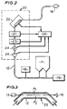
- Fig. 2 is a generalized schematic with the instrumentation being shown generally at 20, the particulate coal (having a known density) exits pressurized feed hopper 11 and is entrained in the transport gas 19, for example nitrogen, and transported through the conduit 12 to a burner 18 of the gasifier 9.
- the particulate coal Prior to entering the burner 18, the particulate coal passes through a velocity sensor 21, a slow but accurate density metre 23 and a fast but inaccurate gamma radiation density metre 22.
- pressure 24 and temperature 25 transducers are used, all to be subsequently described. All measurement signals are fed into a computer 26.
- the slow density metre 23 may be, for example, a radial gamma densitometer.
- a curved section of the conduit 12 for the fast radiation density measurement by the gamma ray densitometer 22 and a straight section of conduit is used for the slower, but more accurate, radial gamma ray densitometer 23.
- Fig. 3 is an enlargement of the curved section of the conduit 12 through which particulates flow past the gamma densitometer 22 to the gasifier 9.
- a gamma radiation source 13 is positioned so as to direct gamma radiation along the center of the conduit 12 where it is received by a radiation detector 15 for determining the absolute density standard.
- Radiation from the source 13 which is detected by the detector 15 is attenuated by the conduit 12 and by the particulate matter (and gas) flowing therethrough. Because of the curved conduit 12, the particulates flowing therethrough will normally assume a two-phase flow having densities ⁇ 1 and ⁇ 2 where ⁇ 1 is greater than ⁇ 2. For very low and very high densities, ⁇ 1 is approximately equal to ⁇ 2, i.e., approximately single-phase flow. For intermediate densities, excessive transport gas would be introduced (thereby diluting the heating value of the syngas) and the gamma densitometer 22 is less accurate; therefore, a high density method and apparatus is required. For a small diameter (say 15 mm) conduit 12, the source may be on the order of 100 mCi. Where a straight section of conduit 12 is used, as with radial densitometer 23, the source 13 and detector 15 are located in diametrically opposing positions.
- a second density metre 22 is used to obtain a density measurement with a fast response time.
- the density metre 22 may be (as noted) a gamma density metre or any other direct or indirect fast method of measuring density. Since the density measurement varies with time, the accurate, and time-averaged, radiation measurement of the radial gamma ray densitometer 23 is used (as subsequently described) to continually recalibrate the second (fast) density measurement 22 approximately every 10 seconds.
- the calibrated measurement of the fast density metre 22 is transmitted via a conductor 40 to a mass flow calculating circuit 37 where it is combined with the coal velocity 33 to obtain the mass flow 32 which is used to control the operating conditions of the gasifier.
- the coal velocity 33 may be determined by a velocity cross correlator 21 using capacitance sensors 27, 28 and a signal conditioner 29. The required sensor spacing depends on the nature of the flow. Pressure and temperature are obtained by appropriate sensors 24 and 25, respectively.
- An integrat-ing computer 26, may be used to integrate the velocity, density, pressure and temperature signals to determine total mass flow, corrected for transport gas contribution, to obtain f coal the volume fraction of coal alone.
- Fig. 4 shows a schematic of the system instrumentation 20 integrated with a computer 26.
- Particulate coal flows through the conduit 12 toward the gasifier 9 and the following measurements are obtained: temperature is obtained by the temperature sensor 25; the pressure by pressure sensor 24; slow density by the radial gamma ray densitometer 23 (which measurement includes coal and the transport gas); fast density by the curved gamma densitometer 22; and velocity by the velocity sensors 27, 28, signal conditioner 29 and velocity cross correlator 21. All five resulting signals are input to the computer 26.
- the pressure 24 and temperature 25 measurements are combined to obtain the transport gas density, r gas , in the r gas calculating circuit 34 which, in turn, is combined with the radial gamma density measurement 23 (r gamma ) in the gas compensation circuit 35 to obtain a compensated gamma density measurement (i.e., f coal r coal ) which is shown as the output 30 of the computer 26.
- the velocity cross correlator 21 receives inputs from two capacitance sensors 27, 28 via the signal conditioner 29 and computes the average coal velocity v coal 33 in the conduit 12.
- the fast but inaccurate density measurement obtained by the curved gamma densitometer 22 is combined via the conductor 40 with the velocity measurement v coal 33 to obtain the mass flow (fast but inaccurate) at the terminal 32 of computer 26.
- the output at the terminal 32 is used to control gasifier operation for maintaining a constant mass flow rate.
- the signal from the fast density measurement 22 is corrected periodically (every 10 seconds, for example) in a calibration/-switching circuit 36 by a compensated density signal 30 via the conductor 30' to obtain a corrected density measurement on the conductor 40 that is accurate, fast and compensated for transport gas density.
- the transport gas accounts for only about 5% or less of the suspension density, especially at high suspension densities.
- the second densitometer signal 22 could be calibrated directly with the uncompensated gamma density r gamma signal 23 (via the dashed line 23') to give a fast, calibrated but uncompensated, density measurement on the conductor 40.
- This signal could then be combined with the velocity measurement v coal 33 and would result in only a small error in the mass flow signal at the terminal 32.
- the calibrated (and, if required, compensated) density measurement on the conductor 40 is combined with the velocity measurement v coal 33 to obtain a corrected mass flow measurement at the terminal 32 which can then be used (e.g.) to control the flow of particulate coal from the hopper 11 to maintain a desired mass flow rate which is essentially constant over a long period of time.
Landscapes
- Chemical & Material Sciences (AREA)
- General Physics & Mathematics (AREA)
- Physics & Mathematics (AREA)
- Fluid Mechanics (AREA)
- Immunology (AREA)
- Biochemistry (AREA)
- General Health & Medical Sciences (AREA)
- Analytical Chemistry (AREA)
- Life Sciences & Earth Sciences (AREA)
- Pathology (AREA)
- Health & Medical Sciences (AREA)
- Engineering & Computer Science (AREA)
- Combustion & Propulsion (AREA)
- Oil, Petroleum & Natural Gas (AREA)
- Organic Chemistry (AREA)
- Measuring Volume Flow (AREA)
- Analysing Materials By The Use Of Radiation (AREA)
Claims (5)
- Système pour la détermination du débit masse d'un solide transporté à travers un conduit (12) par un milieu de transport gazeux, comprenant:a) un premier densitomètre gamma (23) pour la détermination de la densité masse totale dudit solide et dudit milieu de transport;b) un deuxième densitomètre à réaction rapide (22) pour l'obtention d'une mesure directe ou indirecte de la densité masse totale dudit solide et dudit milieu de transport;c) un détecteur de pression (24) et de température (25) pour la mesure de la pression et de la température dudit milieu de transport;d) un moyen (26) pour le calcul de la densité dudit milieu de transport en utilisant lesdites mesures de pression et de température;e) un ordinateur d'intégration (34, 35) pour le calcul de la densité des solides en utilisant le signal de sortie dudit premier densitomètre gamma, après compensation par la densité dudit milieu de transport afin d'obtenir une mesure de densité compensée; caractérisé parf) un moyen (36) pour l'étalonnage périodique de la lecture dudit deuxième densitomètre (22) avec ladite mesure de densité compensée pour obtenir une mesure de densité étalonnée;g) un moyen (21) pour la mesure de la vitesse dudit courant de solides; eth) un moyen d'ordinateur (37) pour le calcul du débit masse desdits solides à partir de ladite lecture de vitesse et de ladite mesure de densité étalonnée.
- Système selon la revendication 1, caractérisé en ce que ledit deuxième densitomètre est un densitomètre gamma situé sur une portion courbe dudit conduit.
- Système selon la revendication 1, caractérisé en ce que ledit premier densitomètre est un densitomètre gamma radial.
- Méthode de contrôle du débit masse vers un gazéificateur (9) d'un solide transporté pneumatiquement dans un milieu gazeux à travers un conduit (12) vers ledit gazéificateur (9), comprenant les étapes de:a) mesure de la densité gamma totale dudit solide et dudit milieu gazeux à l'aide d'un premier densitomètre (23);b) mesure de la pression et de la température dudit milieu gazeux;c) calcul de la densité dudit milieu gazeux;d) soustraction de la densité du gaz de ladite lecture de densité gamma totale pour l'obtention d'une lecture de densité gamma compensée;e) obtention d'une deuxième mesure de densité gamma totale, en utilisant un deuxième densitomètre (22); caractérisée par:f) l'étalonnage dudit deuxième densitomètre par:(1) calcul de la lecture moyenne dudit deuxième densitomètre sur la dernière période de prise de moyenne pour ladite première mesure de densité gamma et étalonnage de cette lecture pour la rendre égale à ladite lecture de densité gamma compensée pour obtenir une lecture étalonnée;(2) obtention d'une lecture de débit masse corrigée en cadrant la lecture dudit deuxième densitomètre avec ladite lecture étalonnée jusqu'à ce que la lecture dudit deuxième densitomètre est mise à jour par la prochaine lecture de densité gamma compensée; etg) le contrôle du débit masse dudit solide vers ledit gazéificateur (9) par un ajustement des conditions opératoires dudit gazéificateur (9) à l'aide de ladite lecture de débit masse corrigée.
- Méthode selon la revendication 4, caractérisée en ce que ladite deuxième mesure de densité est obtenue en mesurant le rayonnement gamma à travers une section courbe dudit conduit.
Applications Claiming Priority (2)
| Application Number | Priority Date | Filing Date | Title |
|---|---|---|---|
| US513130 | 1990-04-23 | ||
| US07/513,130 US5132917A (en) | 1990-04-23 | 1990-04-23 | Method and apparatus for the combined use of dual density measurements to achieve a fast and accurate density measurement in pneumatically transported solids |
Publications (3)
| Publication Number | Publication Date |
|---|---|
| EP0454230A2 EP0454230A2 (fr) | 1991-10-30 |
| EP0454230A3 EP0454230A3 (en) | 1993-03-31 |
| EP0454230B1 true EP0454230B1 (fr) | 1996-02-21 |
Family
ID=24042001
Family Applications (1)
| Application Number | Title | Priority Date | Filing Date |
|---|---|---|---|
| EP91200926A Expired - Lifetime EP0454230B1 (fr) | 1990-04-23 | 1991-04-18 | Procédé et dispositif pour déterminer le débit masse des solides convoyés pneumatiquement |
Country Status (6)
| Country | Link |
|---|---|
| US (1) | US5132917A (fr) |
| EP (1) | EP0454230B1 (fr) |
| JP (1) | JP3023516B2 (fr) |
| CA (1) | CA2040944C (fr) |
| DE (1) | DE69117210T2 (fr) |
| ES (1) | ES2084087T3 (fr) |
Cited By (1)
| Publication number | Priority date | Publication date | Assignee | Title |
|---|---|---|---|---|
| US9267831B2 (en) | 2010-01-29 | 2016-02-23 | General Electric Company | Systems and methods for determining a real time solid flow rate in a solid-gas mixture |
Families Citing this family (25)
| Publication number | Priority date | Publication date | Assignee | Title |
|---|---|---|---|---|
| US5307667A (en) * | 1992-07-13 | 1994-05-03 | Ford Motor Company | Response time test apparatus for a mass air flow sensor |
| US5734596A (en) * | 1994-04-26 | 1998-03-31 | The United States Of America As Represented By Administrator National Aeronautics And Space Administration | Self-calibrating and remote programmable signal conditioning amplifier system and method |
| US5924794A (en) * | 1995-02-21 | 1999-07-20 | Fsi International, Inc. | Chemical blending system with titrator control |
| US5698794A (en) * | 1995-12-19 | 1997-12-16 | Thermo Sentron, Inc. | Impact flowmeter for solids |
| DE19728612C2 (de) * | 1997-07-04 | 2001-11-29 | Promecon Prozess & Messtechnik | Verfahren zur Bestimmung der in einer Zweiphasenströmung mit gasförmigem Trägermedium enthaltenen Menge festen und/oder flüssigen Materials |
| EP1156307A1 (fr) * | 2000-05-16 | 2001-11-21 | Entreprise Generale De Chauffage Industriel Pillard | Procédé d'étalonnage de mesure du débit massique d'une matière en vrac |
| US7128812B1 (en) * | 2001-03-19 | 2006-10-31 | Cupit Carl E | Apparatus and method for determining the level in a coke drum |
| US20080264182A1 (en) * | 2003-08-22 | 2008-10-30 | Jones Richard T | Flow meter using sensitive differential pressure measurement |
| CN100450901C (zh) * | 2005-07-11 | 2009-01-14 | 西安热工研究院有限公司 | 一种多支路出料的干煤粉加压密相输送装置 |
| NO327159B1 (no) * | 2006-08-17 | 2009-05-04 | Rolls Royce Marine As | Fremgangsmåte for nåtidsmåling av strømningsrate av tørrlast |
| US7524146B2 (en) * | 2006-11-30 | 2009-04-28 | William Jeffrey Peet | Pneumatic uneven flow factoring for particulate matter distribution system |
| US8010312B2 (en) | 2007-06-30 | 2011-08-30 | Endress + Hauser Flowtec Ag | Medium density measuring system |
| RU2452935C2 (ru) * | 2007-06-30 | 2012-06-10 | Эндресс + Хаузер Флоутек Аг | Измерительная система для среды, протекающей в технологическом трубопроводе |
| DE102007030700A1 (de) * | 2007-06-30 | 2009-05-07 | Endress + Hauser Flowtec Ag | Meßsystem für ein in einer Prozeßleitung strömendes Medium |
| DE102007043907A1 (de) | 2007-09-14 | 2009-03-26 | Siemens Ag | Kalibrierung von Staubmassenstrommess-Systemen |
| JP5677094B2 (ja) | 2008-01-16 | 2015-02-25 | シエル・インターナシヨネイル・リサーチ・マーチヤツピイ・ベー・ウイShell Internationale Research Maatschappij Beslotenvennootshap | 粒状固体材料を加圧式反応器に供給する方法 |
| CN101430269B (zh) * | 2008-12-17 | 2011-02-09 | 华北电力大学 | 气力输送管道中煤粉浓度及相分布的实时检测装置 |
| US8377387B2 (en) | 2010-06-23 | 2013-02-19 | General Electric Company | Fluidization device for solid fuel particles |
| US10386019B2 (en) * | 2013-03-15 | 2019-08-20 | Southwire Company, Llc | Flow control and gas metering process |
| JP6121309B2 (ja) * | 2013-11-08 | 2017-04-26 | 三菱日立パワーシステムズ株式会社 | チャー供給ホッパ、チャー回収装置及びガス化炉システム |
| JP6109796B2 (ja) | 2014-09-16 | 2017-04-05 | 三菱日立パワーシステムズ株式会社 | 粉体搬送装置及びチャー回収装置 |
| US10494200B2 (en) | 2016-04-25 | 2019-12-03 | Chevron Phillips Chemical Company Lp | Measurement of product pellets flow rate |
| DE102018130067A1 (de) | 2018-11-28 | 2020-05-28 | Volkswagen Aktiengesellschaft | Verfahren zur Messung und Regelung von technischen Gasströmungen, Vorrichtung zur Messung und Regelung von technischen Gasströmungen |
| CN109540724B (zh) * | 2018-11-30 | 2024-02-27 | 南京林业大学 | 一种生物质燃气焦油持续在线测量系统及测量方法 |
| CN115790758B (zh) * | 2023-02-03 | 2023-04-28 | 海默新宸水下技术(上海)有限公司 | 基于温度补偿的伽马传感器计数矫正方法 |
Family Cites Families (15)
| Publication number | Priority date | Publication date | Assignee | Title |
|---|---|---|---|---|
| GB1235856A (en) * | 1967-09-06 | 1971-06-16 | Nat Res Dev | Improvements in or relating to the measurement of the flow of a particulate material |
| US3635082A (en) * | 1969-04-23 | 1972-01-18 | United States Steel Corp | Apparatus for measuring mass flow of fluidborne solids |
| DE2554565A1 (de) * | 1975-12-04 | 1977-06-16 | Otto & Co Gmbh Dr C | Anlage zur druckvergasung feinkoerniger brennstoffe |
| DE2757032A1 (de) * | 1977-12-21 | 1979-06-28 | Krupp Koppers Gmbh | Verfahren zur ermittlung des bei der partialoxydation von feinkoernigen bis staubfoermigen festen brennstoffen dem vergaser zugefuehrten brennstoffstromes |
| US4490077A (en) * | 1981-07-28 | 1984-12-25 | Nippon Kokan Kabushiki Kaisha | Apparatus for continuously measuring flow rate of fine material flowing through transport pipe |
| FR2557690B1 (fr) * | 1983-12-30 | 1986-05-09 | Inst Francais Du Petrole | Procede et dispositif de mesure des debits des phases liquide et gazeuse d'un fluide diphasique en ecoulement |
| US4739647A (en) * | 1985-01-31 | 1988-04-26 | Monticelli Jr F Ronald | Apparatus and method for continuously monitoring non-condensable gases in a flow of mixed gases |
| DE3513037A1 (de) * | 1985-04-11 | 1986-10-30 | INTERATOM GmbH, 5060 Bergisch Gladbach | Einrichtung zum messen des massendurchsatzes eines in einem kanal bewegten fluids |
| US4683759A (en) * | 1985-12-23 | 1987-08-04 | Texaco Inc. | Characterization of two-phase flow in pipes |
| US4782711A (en) * | 1986-10-14 | 1988-11-08 | K-Flow Division Of Kane Steel Co., Inc. | Method and apparatus for measuring mass flow |
| US4751842A (en) * | 1987-01-05 | 1988-06-21 | Texaco Inc. | Means and method for measuring a multi-phase distribution within a flowing petroleum stream |
| GB8720356D0 (en) * | 1987-08-28 | 1987-10-07 | Thorn Emi Flow Measurement Ltd | Fluid meter |
| US4884457A (en) * | 1987-09-30 | 1989-12-05 | Texaco Inc. | Means and method for monitoring the flow of a multi-phase petroleum stream |
| US4838738A (en) * | 1987-10-28 | 1989-06-13 | Shell Oil Company | Pressure compensated weigh system |
| US4969408A (en) * | 1989-11-22 | 1990-11-13 | Westinghouse Electric Corp. | System for optimizing total air flow in coal-fired boilers |
-
1990
- 1990-04-23 US US07/513,130 patent/US5132917A/en not_active Expired - Lifetime
-
1991
- 1991-04-18 ES ES91200926T patent/ES2084087T3/es not_active Expired - Lifetime
- 1991-04-18 EP EP91200926A patent/EP0454230B1/fr not_active Expired - Lifetime
- 1991-04-18 DE DE69117210T patent/DE69117210T2/de not_active Expired - Fee Related
- 1991-04-22 CA CA002040944A patent/CA2040944C/fr not_active Expired - Fee Related
- 1991-04-22 JP JP3116533A patent/JP3023516B2/ja not_active Expired - Fee Related
Cited By (1)
| Publication number | Priority date | Publication date | Assignee | Title |
|---|---|---|---|---|
| US9267831B2 (en) | 2010-01-29 | 2016-02-23 | General Electric Company | Systems and methods for determining a real time solid flow rate in a solid-gas mixture |
Also Published As
| Publication number | Publication date |
|---|---|
| DE69117210T2 (de) | 1996-07-25 |
| US5132917A (en) | 1992-07-21 |
| CA2040944C (fr) | 2001-05-15 |
| CA2040944A1 (fr) | 1991-10-24 |
| JP3023516B2 (ja) | 2000-03-21 |
| EP0454230A3 (en) | 1993-03-31 |
| EP0454230A2 (fr) | 1991-10-30 |
| ES2084087T3 (es) | 1996-05-01 |
| JPH04230809A (ja) | 1992-08-19 |
| DE69117210D1 (de) | 1996-03-28 |
Similar Documents
| Publication | Publication Date | Title |
|---|---|---|
| EP0454230B1 (fr) | Procédé et dispositif pour déterminer le débit masse des solides convoyés pneumatiquement | |
| US4231262A (en) | System for measuring entrained solid flow | |
| CA1330726C (fr) | Systeme de mesure de debit d'un fluide | |
| RU2010123979A (ru) | Система вдувания для твердых частиц | |
| US4483199A (en) | Method of measuring solid matter mass flow | |
| CN101644652A (zh) | 差压式密度测量装置与测量方法 | |
| Li et al. | Online monitoring and characterization of dense phase pneumatically conveyed coal particles on a pilot gasifier by electrostatic-capacitance-integrated instrumentation system | |
| CN111853851A (zh) | 燃煤火电机组锅炉一次风速校正与调平方法 | |
| AU2018269028A1 (en) | Methods for designing a flow conduit and apparatus that measures deflection at multiple points to determine flow rate | |
| WO1998052002A1 (fr) | Appareil et procede de mesure du debit de gaz avec liquides entraines | |
| CN212856142U (zh) | 磨煤机 | |
| US4520677A (en) | Solids mass flow indication with radiation | |
| US4275601A (en) | Solids mass flow determination | |
| US4349734A (en) | Flow detector for solids | |
| JP2865282B1 (ja) | 導圧配管パージ装置 | |
| CN86103084A (zh) | 气动输送煤粉流量检测方法及装置 | |
| Green et al. | FLOW MEASUREMENT FOR OPTIMISING THE FEEDRATE OF PULVERISED FUEL TO COAL-FIRED BOILERS | |
| Abernethy et al. | On‐Line Measurement of Mass Flow of Pneumatically Conveyed Solids | |
| JPH0758213B2 (ja) | 微粉炭の流量測定方法及び装置 | |
| RU2215939C2 (ru) | Устройство для автоматического регулирования подачи горючей смеси в горелки котлоагрегата | |
| Kuoppamäki | QUALITY MAINTENANCE OF FLOW MEASUREMENTS IN INDUSTRY. | |
| JP3396281B2 (ja) | 粒子の流量計測装置 | |
| SU1428923A1 (ru) | Расходомер | |
| KR101444364B1 (ko) | 이송 미분탄 유량 측정 장치 및 그를 이용한 유량 측정 방법 | |
| JPS6344126A (ja) | 気流搬送における固体粒子の流量計測方法 |
Legal Events
| Date | Code | Title | Description |
|---|---|---|---|
| PUAI | Public reference made under article 153(3) epc to a published international application that has entered the european phase |
Free format text: ORIGINAL CODE: 0009012 |
|
| AK | Designated contracting states |
Kind code of ref document: A2 Designated state(s): DE ES GB IT NL |
|
| PUAL | Search report despatched |
Free format text: ORIGINAL CODE: 0009013 |
|
| AK | Designated contracting states |
Kind code of ref document: A3 Designated state(s): DE ES GB IT NL |
|
| 17P | Request for examination filed |
Effective date: 19930726 |
|
| 17Q | First examination report despatched |
Effective date: 19940406 |
|
| GRAA | (expected) grant |
Free format text: ORIGINAL CODE: 0009210 |
|
| AK | Designated contracting states |
Kind code of ref document: B1 Designated state(s): DE ES GB IT NL |
|
| ITF | It: translation for a ep patent filed | ||
| REF | Corresponds to: |
Ref document number: 69117210 Country of ref document: DE Date of ref document: 19960328 |
|
| REG | Reference to a national code |
Ref country code: ES Ref legal event code: FG2A Ref document number: 2084087 Country of ref document: ES Kind code of ref document: T3 |
|
| PLBE | No opposition filed within time limit |
Free format text: ORIGINAL CODE: 0009261 |
|
| STAA | Information on the status of an ep patent application or granted ep patent |
Free format text: STATUS: NO OPPOSITION FILED WITHIN TIME LIMIT |
|
| 26N | No opposition filed | ||
| PGFP | Annual fee paid to national office [announced via postgrant information from national office to epo] |
Ref country code: DE Payment date: 19970513 Year of fee payment: 7 |
|
| PG25 | Lapsed in a contracting state [announced via postgrant information from national office to epo] |
Ref country code: DE Free format text: LAPSE BECAUSE OF NON-PAYMENT OF DUE FEES Effective date: 19990202 |
|
| REG | Reference to a national code |
Ref country code: GB Ref legal event code: IF02 |
|
| PGFP | Annual fee paid to national office [announced via postgrant information from national office to epo] |
Ref country code: GB Payment date: 20050330 Year of fee payment: 15 |
|
| PG25 | Lapsed in a contracting state [announced via postgrant information from national office to epo] |
Ref country code: GB Free format text: LAPSE BECAUSE OF NON-PAYMENT OF DUE FEES Effective date: 20060418 |
|
| PGFP | Annual fee paid to national office [announced via postgrant information from national office to epo] |
Ref country code: IT Payment date: 20060430 Year of fee payment: 16 |
|
| GBPC | Gb: european patent ceased through non-payment of renewal fee |
Effective date: 20060418 |
|
| PGFP | Annual fee paid to national office [announced via postgrant information from national office to epo] |
Ref country code: ES Payment date: 20080429 Year of fee payment: 18 |
|
| PGFP | Annual fee paid to national office [announced via postgrant information from national office to epo] |
Ref country code: NL Payment date: 20080424 Year of fee payment: 18 |
|
| PG25 | Lapsed in a contracting state [announced via postgrant information from national office to epo] |
Ref country code: IT Free format text: LAPSE BECAUSE OF NON-PAYMENT OF DUE FEES Effective date: 20070418 |
|
| NLV4 | Nl: lapsed or anulled due to non-payment of the annual fee |
Effective date: 20091101 |
|
| PG25 | Lapsed in a contracting state [announced via postgrant information from national office to epo] |
Ref country code: NL Free format text: LAPSE BECAUSE OF NON-PAYMENT OF DUE FEES Effective date: 20091101 |
|
| REG | Reference to a national code |
Ref country code: ES Ref legal event code: FD2A Effective date: 20090420 |
|
| PG25 | Lapsed in a contracting state [announced via postgrant information from national office to epo] |
Ref country code: ES Free format text: LAPSE BECAUSE OF NON-PAYMENT OF DUE FEES Effective date: 20090420 |