EP0452918B1 - Vorrichtung zum automatischen Aufrichten von Sitzen für eine Teleskoptribüne - Google Patents
Vorrichtung zum automatischen Aufrichten von Sitzen für eine Teleskoptribüne Download PDFInfo
- Publication number
- EP0452918B1 EP0452918B1 EP91106209A EP91106209A EP0452918B1 EP 0452918 B1 EP0452918 B1 EP 0452918B1 EP 91106209 A EP91106209 A EP 91106209A EP 91106209 A EP91106209 A EP 91106209A EP 0452918 B1 EP0452918 B1 EP 0452918B1
- Authority
- EP
- European Patent Office
- Prior art keywords
- guide arm
- foot
- center shaft
- seating system
- movable platform
- Prior art date
- Legal status (The legal status is an assumption and is not a legal conclusion. Google has not performed a legal analysis and makes no representation as to the accuracy of the status listed.)
- Expired - Lifetime
Links
Images


Classifications
-
- E—FIXED CONSTRUCTIONS
- E04—BUILDING
- E04H—BUILDINGS OR LIKE STRUCTURES FOR PARTICULAR PURPOSES; SWIMMING OR SPLASH BATHS OR POOLS; MASTS; FENCING; TENTS OR CANOPIES, IN GENERAL
- E04H3/00—Buildings or groups of buildings for public or similar purposes; Institutions, e.g. infirmaries or prisons
- E04H3/10—Buildings or groups of buildings for public or similar purposes; Institutions, e.g. infirmaries or prisons for meetings, entertainments, or sports
- E04H3/12—Tribunes, grandstands or terraces for spectators
- E04H3/123—Telescopic grandstands
-
- A—HUMAN NECESSITIES
- A47—FURNITURE; DOMESTIC ARTICLES OR APPLIANCES; COFFEE MILLS; SPICE MILLS; SUCTION CLEANERS IN GENERAL
- A47C—CHAIRS; SOFAS; BEDS
- A47C1/00—Chairs adapted for special purposes
- A47C1/12—Theatre, auditorium or similar chairs
- A47C1/126—Theatre, auditorium or similar chairs stowable in floor or wall
Definitions
- the present invention relates generally to an apparatus for automatically turning up and down a number of seats for a telescopic seating system as known from US-A-4 702 043. More particularly, the present invention relates to an apparatus for automatically turning up spectators' seats to assume the upright standing attitude before practically using the telescopic seating system and automatically turning down them to assume the horizontally laid attitude after completion of the practical use of the telescopic seating system.
- a telescopic seating system including a plurality of extensively/contractively movable platforms arranged in tiers is increasingly employed for a building such as a gymnasium or the like facility in order to utilize the floor space more effectively by fully accommodating all the movable platforms in a cavity formed in the one side wall structure of the building when the telescopic seating system is not in use.
- the movable platforms used for the telescopic seating system are arranged in the form of a so-called doll tier stand such that the foremost movable platform is located at the lowermost position and the rearmost movable platform is located at the highest position when the telescopic seating system is practically used while all the movable platforms assume their extended attitude.
- all the movable platforms are extended in the doll tier stand-shaped configuration and all the seats arranged side by side in the transverse direction on each movable platform are simultaneously automatically raised up.
- all the seats are automatically turned down and then all the movable platforms are then successively accommodated in the cavity of the building. Hitherto, the seats on each movable platforms are automatically turned up and down with a large magnitude of power derived from an electric motor or a hydraulic motor.
- a large scale of facility should unavoidably be installed and a large number of electricity is consumed for operating the facility with the result that the telescopic seating system is practically used at an expensive cost with a degraded economical efficiency, e.g., in respect of effective utilization of the gymnasium designed and constructed for various kinds of purposes.
- a raising-up operation has been heretofore performed such that the horizontally laid seats are turned up by lifting them with the top ends thereof grasped by suitable means with the aid of an electric motor or the like means. This leads to the result that the telescopic seating system has a degraded appearance.
- An object of the present invention is to provide an apparatus for automatically turning up and down a number of seats for a telescopic seating system wherein the apparatus is entirely free from the problems inherent to the conventional telescopic seating system.
- Another object of the present invention is to provide an apparatus for automatically turning up and down a number of seats for a telescopic seating system wherein each seat on each movable platform is easily automatically turned up with the aid of a sum of the resilient forces derived from a plurality of coil springs without any necessity for an extra power to be generated by an electric motor or the like means.
- Another object of the present invention is to provide an apparatus for automatically turning up and down a number of seats for a telescopic seating system wherein all the seats arranged on each movable platform side by side in the transverse direction can simultaneously smoothly be turned down without any necessity for an extra power therefor by utilizing successive rearward movement of the movable platform when the telescopic seating system is not put in practical use.
- the present invention provides an apparatus for automatically turning up and down a number of seats for a telescopic seating system including a plurality of movable platforms to be arranged in tiers when the telescopic seating system is in use wherein the movable platforms are successively operatively connected to each other to extend and contract in the forward/rearward directions while the respective seats are arranged side by side in the transverse direction on each movable platform, wherein the apparatus is characterized in that a foot having a single seat fixedly mounted thereon is turned up and down about a support shaft; a housing in the form of a base frame having a substantially U-shaped cross-sectional configuration holds the support shaft for the foot which is immovably inserted through the housing in the transverse direction at the fore end part thereof; a center shaft is rotatably inserted through the housing in the transverse direction at the central part of the housing while extending in parallel with the support shaft and including an extension outside of the outer side wall of the housing; a guide arm is turnably mounted
- the movable platform at the lower stage is displaced in the rearward direction and thereby the guide arm which has been brought in contact with the rear surface of the rear transverse beam at the lower stage collides against a rear transverse beam of the movable platform at the present stage, whereby rearward turning movement of the guide arm is transmitted to the foot which has stood upright, via the center shaft, the tongue-shaped projections and the link plates so as to allow the foot to be turned down.
- the apparatus further includes a rotary member which is fixedly mounted on the extension of the center shaft outside of the guide arm such that an opposing pair of stoppers are protruded toward the guide arm in the axial direction of the center shaft.
- a rotary member which is fixedly mounted on the extension of the center shaft outside of the guide arm such that an opposing pair of stoppers are protruded toward the guide arm in the axial direction of the center shaft.
- One of the stoppers located in front of the center shaft is to be brought in contact with the front surface of the guide arm so as to limit the forward turning movement of the guide arm, while the other stopper located behind the center shaft is to be brought in contact with the rear surface of the guide arm so as to allow the rearward turning movement of the guide arm to be transmitted to the foot via this stopper, the rotary member, the center shaft, the tongue-shaped projections and the link plates.
- the apparatus further includes a third coil spring which is mounted on the extension of the center shaft between the guide arm and the rotary member.
- One end of the third coil spring is fixedly secured to the guide arm, while the other end of the same is fixedly secured to the rotary member so as to allow the guide arm to be normally turnably biased in the forward direction in addition to the resilient force of the second coil spring.
- the guide arm collides against a front transverse beam of the movable platform at the present stage at an intermediate position which is located slightly in front of the upright standing position. Thereafter, the foot continues to be turnably raised up until the upright standing position is reached, merely with the aid of the resilient force derived from the first coil springs.
- Fig. 1 is a side view of an apparatus for automatically turning up and down a number of seats for a telescopic seating system in accordance with an embodiment of the present invention, particularly illustrating that a foot starts turning-up movement in response to forward movement of a movable platform at a certain stage.
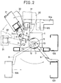
- Fig. 2 is a side view of the apparatus shown in Fig. 1, particularly illustrating that the foot starts turning-down movement in response to rearward movement of the movable platform.
- Fig. 3 is a fragmentary side view of the apparatus, particularly illustrating that the foot assumes an intermediate position (represented by two-dot chain lines) slightly in front of the upright standing position as well as the upright standing position (represented by solid lines) by forward turning movement of a guide arm with the aid of a resilient force derived from a plurality of coil springs.
- Fig. 4 is a fragmentary side view of the apparatus, particularly illustrating the operational relationship between a pair of link plates and a pair of tongue-shaped projections when the foot is fully raised up to assume the upright standing position.
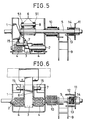
- Fig. 5 is a sectional plan view of the apparatus taken along line IV1 - IV1 and line IV2 - IV2 in Fig. 4.
- Fig. 6 is a front view of the apparatus as seen in the operative state in Fig. 4.
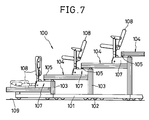
- Fig. 7 is a partially sectioned side view of the telescopic seating system for which a number of apparatuses of the present invention are employed.
- a telescopic seating system generally designated by reference numeral 100 for which an apparatus for automatically turning up and down a number of seats (hereinafter referred to simply as an apparatus) according to the present invention is employed.
- Fig. 7 is a fragmentary side view of the telescopic seating system 100. When the telescopic seating system 100 is practically used, the whole telescopic seating system 100 is forwardly displaced along a floor surface 109.
- a plurality of movable platforms 104 having a number of spectators' seats 108 mounted side by side in the transverse direction thereon are successively drawn from the lower stage side in the forward direction together with base boards 101 and support columns 103 fixedly secured to the movable platforms 104 with the aid of a number of rollers 102 which are driven by an actuating mechanism (not shown).
- the telescopic seating system 100 On completion of the slidable movement of the movable platform 104 in the forward direction, the telescopic seating system 100 exhibits the fully extended state and all the platforms 104 are arranged in tiers, as shown in Fig. 7. After a certain performance is over, the telescopic seating system 100 should be brought in the inoperative state.
- Each movable platform 104 to be arranged in tiers in the operative state includes a plurality of seats 108 in the side-by-side relationship each of which is allocated to one of plural blocks equally spaced along the transversely extending movable platform 104.
- FIG. 7 the apparatus in accordance with the embodiment of the present invention designated by reference numeral 107 in Fig. 7 will be described below with reference to Fig. 1 to Fig. 6.
- two apparatuses 107 are arranged on the both sides of each spectator's seat 108.
- description will be made below as to one of the two apparatuses 107 for the purpose of simplification of description, because all components constituting each of the left-hand and right-hand apparatuses are same to each other with the exception that they are arranged in the symmetrical relationship.
- the apparatus 107 is basically composed of a base frame 1, a support shaft 2, a foot 3, a pair of coil springs 4 each adapted to normally turn the foot 3 in the clockwise direction as seen in Fig. 2 by the resilient force derived therefrom, a center shaft 5, a pair of link plates 6, a guide arm 9, a coil spring 10 adapted to normally turn the guide arm 9 in the clockwise direction as seen in Fig. 1 by the resilient force derived therefrom, a turn plate 11, an opposing pair of stoppers 12 and 13 and a coil spring 14 adapted to normally turn the guide arm 9 by the resilient force derived therefrom.
- the base frame 1 is designed in the substantially U-shaped cross-sectional configuration of which front side is opened to the outside.
- the foot 3 is designed in the substantially square cross-sectional configuration and includes a foot member 31 and a transverse member having the substantially L-shaped cross-sectional configuration so as to allow a spectator's seat 108 to be fixedly mounted thereon (see Fig. 3).
- the foot 3 is turnably supported by the support shaft 2 extending through the base end part thereof in the transverse direction to turn about the support shaft 2 in the clockwise/ anticlockwise direction.
- the pair of coil springs 4 each having a large magnitude of resilient force are mounted on the support shaft 2 such that one end of each of the coil springs 4 is fixedly secured to the base frame 1 and the other end of the same is fixedly secured to the foot 3, whereby the foot 3 is normally biased in the raising-up direction by the resilient force derived from the coil springs 4.
- a front transverse shaft 7 is inserted through the foot 3 at the intermediate position of the same while extending in parallel with the support shaft 2.
- a foot member 31 constituting the lower end part of the spectator's seat 108 is fixedly attached to the foot 3 such that the spectator's seat 108 is turned in the raising-up/lowering directions together with the foot 3.
- the center shaft 5 is located behind the support shaft 2 while extending through the base frame 1 in the transverse direction of the spectator's seat 108. It is obvious that the center shaft 5 is inserted through the opposite base frame 1 (not shown) in the same manner.
- a pair of tongue-shaped projections 51 are integrated with a larger diameter portion of the center shaft 5 within the hollow space of the base frame 1 to turn about the center shaft 5 together with the same (see Fig. 4 and Fig. 5). It should be noted that the tongue-shaped projections 51 rearwardly extend in the slantwise downward direction when the foot 3 stands upright.
- the front transverse shaft 7 is inserted through the pair of link plates 6 in parallel with the center shaft 5 and a rear transverse shaft 8 is inserted through the pair of tongue-shaped projections 51 in parallel with the center shaft 5, whereby the foot 3 is operatively connected to the projections 51 via the link plates 6, the fore transverse shaft 7 and the rear transverse shaft 8.
- the center shaft 5 has an extension outside of one outer side wall of the base frame 1, and the base end of the guide arm 9 is rotatably mounted on the extension of the center shaft 5.
- the coil spring 10 adapted to normally bias the foot 3 in the raising-up direction by the resilient force derived therefrom is mounted on the extension of the center shaft 5 between the base frame 1 and the guide arm 9 such that one end of the coil spring 10 is fixedly secured to the base frame 1 and the other end of the same is fixedly secured to the guide frame 9. While any outer force is not exerted on the guide arm 9, the fore end part of the guide arm 9 is turnably displaced in the forward direction by the resilient force of the coil spring 10 only.
- the guide arm 9 when an outer force is exerted on the guide arm 9 from the front side, the guide arm 9 is turnably displaced in the rearward direction.
- the guide arm 9 is dimensioned to have a length enough to turn within the range where a rear transverse beam 106 of the movable platform 104 at the lower stage moves in the forward/rearward directions (see Fig. 1 and Fig. 2).
- a circular rotary member 11 is fixedly mounted on the extension of the center shaft 5 at the outermost end of the same in the coaxial relationship, and the stoppers 12 and 13 are projected inside of the rotary member 11 (extending toward the base frame 1) in the spaced relationship such that one of them, i.e., the stopper 12 comes in contact with the front surface of the guide arm 9 and the other one, i.e., the stopper 13 comes in the rear surface of the guide arm 9.
- the both stoppers 12 and 13 may be integrated with the rotary member 11 by employing a casting process.
- a coil spring 14 adapted to normally bias the guide arm 9 in the clockwise direction by the resilient force derived therefrom is mounted on the extension of the center shaft 5 between the guide arm 9 and the rotary member 11.
- the apparatus 107 of the present invention is constituted by the aforementioned components to provide a single assembly.
- the apparatus 107 serves as a base portion of each spectator's seat 108 adjacent to the support column 103.
- a plurality of spectator's seats 108 are arranged side by side in the transverse direction in the spaced relationship on the movable platform 104 at each stage and each spectator's seat 108 is allocated to one of a plurality of blocks along the movable platform 104.
- an operator controls a controller (not shown) such that the movable platform 104 are successively displaced in the forward direction one after another starting with the lowermost movable platform 104.
- a movable body (not shown) arranged on the bottom side of the movable platform 104 at the lowermost stage stars forward movement.
- the operator controls the controller so as to operate the driving unit for the telescopic seating system 100 in the opposite direction, whereby the movable platforms 104 are successively displaced in the rearward direction starting with the lowermost movable platform 104.
- the movable platform 104 at the lower stage (the movable body (not shown) on the bottom side in a case of the movable platform 104 at the lowermost stage) is displaced in the rearward direction
- the foremost end of the guide arm 9 at the present stage is brought in contact with the front surface of the rectangular steel plate of the movable platform 104 at the present stage.
- the transverse beams 106 at the lower stage is displaced in the rearward direction
- the foremost end of the guide arm 9 at the present stage is turnably displaced in the rearward direction against the resilient force of the coil spring 10 (see Fig. 2).
- the stopper 13 which has been brought in contact with the rear surface of the guide arm 9 is rotated in the anticlockwise direction as the guide arm 9 is turned.
- This causes the foot 3 which has been fully raised up to be forwardly turned to the intermediate position via the link plates 6 which are operatively connected to the rotary member 11 integrated with the center shaft 5 (see Fig. 2).
- the foremost end of the guide arm 9 continues rearward turning movement of the guide arm 9 and is then forcibly placed on the upper surface of the transverse beam 106 for the movable platform 104 at the lower stage, the movable platform 104 at the present stage starts rearward movement.
- an abutment plate 32 fastened to the rear surface of a foot stand 31 collide against a front nose 105 at the foremost end of the movable platform 104 at the upper stage, whereby the foot 3 is increasingly turned down until it assumes the horizontally laid attitude. Consequently, a series of spectators' seats 108 arranged side by side in the transverse direction on the movable platform 104 at the present stage 104 can completely be laid down in the inoperative state on the upper surface of the movable platform 104, as represented by two-dot chain lines in Fig. 2.
- the present invention has been described above as to a case where a number of spectators' seats 108 are arranged in the transverse direction in the equally spaced relationship for the telescopic seating system 100.
- the present invention may equally be applied to a singe seat with the same advantages as those mentioned above.
- the apparatus of the present invention is provided with a pair of coil springs within the interior of the U-shaped base frame each adapted to normally bias the foot in the raising-up direction and a coil spring mounted on an extension of the center shaft between the base frame and the guide arm to normally bias the guide arm in the direction of forward turning movement.
- the arrangement of the coil springs in that way generates a large magnitude of resilient force effective for raising up the foot and thereby assures that the foot can quickly and reliably stand upright without necessity for any extra power to be derived from an electric motor or the like means when the telescopic seating system is in use. Consequently, a function of the telescopic seating system can substantially be improved at an inexpensive cost of installation with a minimized quantity of consumed electricity.
- the aforementioned springs i.e., essential components for the apparatus of the present invention are arranged in the positionally well-balanced state not only within the interior of the base beam but also outside of the base frame, a magnitude of reactive force against the resilient force derived from the aforementioned coil springs can be reduced when each spectator's seat is laid down to assume the horizontally laid position after completion of the practical use of the telescopic seating system. Therefore, a turning-down operation can be performed for all the spectators' seats with a small magnitude of extra force when the telescopic seating system is not in use.
Landscapes
- Engineering & Computer Science (AREA)
- Architecture (AREA)
- Civil Engineering (AREA)
- Structural Engineering (AREA)
- Health & Medical Sciences (AREA)
- Dentistry (AREA)
- General Health & Medical Sciences (AREA)
- Chairs For Special Purposes, Such As Reclining Chairs (AREA)
Claims (6)
- Vorrichtung, um für ein teleskopierbares Bestuhlungssystem (100) eine Anzahl von Sitzen (108) automatisch nach oben und unten zu drehen, enthaltend eine Mehrzahl von beweglichen Plattformen (104), die in Reihen angeordnet sein sollen, wenn sich das teleskopierbare Bestuhlungssystem (100) im Gebrauch befindet, wobei die beweglichen Plattformen zum Ausfahren und Zusammenziehen in Vorwärts/Rückwärtsrichtung aufeinanderfolgend funktionell miteinander verbunden sind, während die Sitze (108) nebeneinander in Querrichtung auf jeder beweglichen Plattform (104) angeordnet sind, wobei die Vorrichtung weiter umfaßt,
ein Fuß (3) mit einem fest darauf angebrachten einzelnen Sitz (108) wird um eine Tragwelle (2) nach oben und unten gedreht,
ein Gehäuse (1) in Form eines Grundrahmens mit einer im wesentlichen U-förmigen Querschnittausbildung hält die Tragwelle (2) für den Fuß (3), welche unbeweglich durch das Gehäuse (1) in Querrichtung an dessen vorderem Endteil eingesetzt ist,
eine Mittelwelle (5) ist drehbar durch das Gehäuse (1) in Querrichtung am mittleren Teil des Gehäuses (1) eingesetzt, während sie sich parallel zur Tragwelle (2) erstreckt und eine Verlängerung außerhalb der äußeren Seitenwand des Gehäuses (1) einschließt
ein Führungsarm (9) ist derart drehbar auf der Verlängerung der Mittelwelle (5) angebracht, daß das vorderste Endteil des Führungsarms (9) auf der Oberseite eines hinteren Querträgers (106) für eine bewegliche Plattform (104) auf der tieferen Stufe liegt, wenn sich das teleskopierbare Bestuhlungssystem (100) nicht im Gebrauch befindet, und gegen die hintere Oberfläche eines vorderen Querträgers (106) anstößt, wenn sich das teleskopierbare Bestuhlungssystem im Gebrauch befindet,
ein Paar erste Schraubenfedern (4) ist auf beiden Seiten des Fußes (3) innerhalb des Gehäuseinneren (1) auf der Tragwelle (2) angebracht, wobei ein Ende jeder der ersten Schraubenfedern (4) fest am Fuß (3) befestigt ist, und das andere Ende derselben fest an der Tragwelle (2) befestigt ist, um es zu ermöglichen, daß der Fuß (3) durch die von den ersten Schraubenfedern (4) stammende Federkraft normalerweise in Richtung des Nachobendrehens vorgespannt ist,
eine zweite Schraubenfeder (10) ist auf der Verlängerung der Mittelwelle (5) außerhalb der äußeren Seitenwand des Gehäuses (1) zwischen dem Gehäuse (1) und dem Führungsarm (9) angebracht, wobei ein Ende der zweiten Schraubenfeder (5) fest an der Mittelwelle (5) befestigt ist, und das andere Ende derselben fest am Führungsarm (9) befestigt ist, um es zu ermöglichen, daß der Führungsarm (9) durch die von der zweiten Schraubenfeder (10) stammende Federkraft normalerweise drehbar in Vorwärtsrichtung vorgespannt ist,
ein Paar zungenförmiger Vorsprünge (51) ist innerhalb des Gehäuseinneren (1) fest auf der Mittelwelle (5) angebracht, während sie sich von der Mittelwelle (5) aus in schräg nach unten geneigter Richtung nach hinten erstrecken, wobei die zungenförmigen Vorsprünge (51) eine durch sie hindurch in Querrichtung an ihrem äußeren Ende eingesetzte hintere Welle (8) aufweisen, und
ein Paar Verbindungsplatten (8) erstreckt sich zwischen einer in Querrichtung durch den Fuß (3) eingesetzten vorderen Welle (7) und einer hinteren Welle (8) auf den zungenförmigen Vorsprüngen, so daß eine funktionelle Verbindung zwischen dem Fuß (13) und dem Führungsarm (9) über die zungenförmigen Vorsprünge (51) und die Mittelwelle (5) eingerichtet wird, wobei sich die Verbindungsplatten (6) hinter der Mittelwelle (5) von der vorderen Welle (7) auf dem Fuß (3) gekrümmt nach unten zur hinteren Welle (8) auf den zungenförmigen Vorsprüngen (51) erstrecken,
wodurch als Reaktion auf eine Vorwärtsbewegung der beweglichen Plattform (104) auf der tieferen Stufe der Führungsarm (9) durch die von den zweiten Schraubenfedern (10) stammende Federkraft in Vorwärtsrichtung gedreht wird, und dadurch über die Mittelwelle (5), die zungenförmigen Vorsprünge (51) und die Verbindungsplatten (6) der Fuß mit Hilfe der von den ersten Schraubenfedern (4) stammenden Federkraft drehbar aufgerichtet wird, so daß er die aufrechtstehende Stellung einnimmt. - Vorrichtung um für ein teleskopierbares Bestuhlungssystem (100) eine Anzahl von Sitzen (108) automatisch nach oben und unten zu drehen, nach Anspruch 1, dadurch gekennzeichnet, daß bei Abschluß der praktischen Nutzung des teleskopierbaren Bestuhlungssystems (100) die bewegliche Plattform (104) auf der tieferen Stufe in Rückwärtsrichtung verschoben wird, und dadurch der Führungsarm (9), der in Berührung mit der hinteren Oberfläche des hinteren Querträgers (106) der beweglichen Plattform (104) auf der tieferen Stufe gebracht worden ist, gegen den hinteren Querträger (106) der beweglichen Plattform (104) auf der vorliegenden Stufe anstößt, wodurch die Rückwärts-Drehbewegung des Führungsarms (9) über die Mittelwelle (5), die zungenförmigen Vorsprünge (51) und die Verbindungsplatten (6) auf den Fuß (3) übertragen wird, der aufrecht gestanden hat, so daß es ermöglicht wird, den Fuß (3) nach unten zu drehen.
- Vorrichtung um für ein teleskopierbares Bestuhlungssystem (100) eine Anzahl von Sitzen (108) automatisch nach oben und unten zu drehen, nach Anspruch 1, dadurch gekennzeichnet, daß die bewegliche Plattform (104) auf der vorliegenden Stufe in Rückwärtsrichtung verschoben wird, die hintere Oberfläche des Fußes (3) gegen eine vordere Nase (105) einer beweglichen Plattform (104) auf der oberen Stufe anstößt, wodurch der Fuß (3) entgegen der Federkraft der ersten Schraubenfedern (4) vollständig nach unten gedreht wird, so daß er die horizontal niedergelegte Stellung einnimmt.
- Vorrichtung um für ein teleskopierbares Bestuhlungssystem (100) eine Anzahl von Sitzen (108) automatisch nach oben und nach unten zu drehen, nach Anspruch 1, dadurch gekennzeichnet, daß ein Drehteil (11) fest auf der Verlängerung der Mittelwelle (5) außerhalb des Führungsarms (9) angebracht ist, wobei das Drehteil (11) ein Paar einander gegenüberliegender Anschläge (12, 13) aufweist, welche in axialer Richtung der Mittelwelle (5) aus diesem in Richtung des Führungsarms (9) überstehen, wobei einer (12) der Anschläge (12, 13), der vor der Mittelwelle (5) angebracht ist, in Berührung mit der vorderen Oberfläche des Führungsarms (9) gebracht wird, so daß er eine Vorwärts-Drehbewegung des Führungsarms (9) begrenzt, und der andere (13) derselben, der hinter der Mittelwelle (5) angeordnet ist, in Berührung mit der hinteren Oberfläche des Führungsarms (9) gebracht wird, so daß es ermöglicht wird, daß eine Rückwärts-Drehbewegung des Führungsarms (9) über diesen Anschlag (13), das Drehteil (11), die Mittelwelle (5), die zungenförmigen Vorsprünge (51) und die Verbindungsplatten (6) auf den Fuß (3) übertragen wird.
- Vorrichtung um für ein teleskopierbares Bestuhlungssystem (100) eine Anzahl von Sitzen (108) automatisch nach oben und unten zu drehen, nach Anspruch 1, dadurch gekennzeichnet, daß eine dritte Schraubenfeder (14) auf der Verlängerung der Mittelwelle zwischen dem Führungsarm (9) und dem Drehteile (11) angebracht ist, wobei ein Ende der dritten Schraubenfeder (14) fest am Führungsarm (9) befestigt ist, und das andere Ende desselben fest am Drehteil (11) befestigt ist, um es zu ermöglichen, daß der Führungsarm (9) normalerweise drehbar in Vorwärtsrichtung vorgespannt ist, zusätzlich zur Federkraft der zweiten Schraubenfeder (10).
- Vorrichtung um für ein teleskopierbares Bestuhlungssystem (100) eine Anzahl von Sitzen (108) automatisch nach oben und nach unten zu drehen, nach Anspruch 1, dadurch gekennzeichnet, daß der Führungsarm (9) während einer Vorwärts-Drehbewegung desselben an einer Zwischenposition gegen einen vorderen Querträger (110) der beweglichen Plattform (104) auf der vorliegenden Stufe anstößt, und danach der Fuß (3) weiter drehbar aufgerichtet wird, bis die aufrechtstehende Position erreicht ist, lediglich mit Hilfe der Federkraft, die von den ersten Schraubenfedern (4) stammt, wobei die Zwischenposition geringfügig vor der aufrechtstehenden Position angeordnet ist.
Applications Claiming Priority (2)
| Application Number | Priority Date | Filing Date | Title |
|---|---|---|---|
| JP2102551A JPH041371A (ja) | 1990-04-18 | 1990-04-18 | 伸縮式階段状観覧席の椅子自動起立転倒装置 |
| JP102551/90 | 1990-04-18 |
Publications (2)
| Publication Number | Publication Date |
|---|---|
| EP0452918A1 EP0452918A1 (de) | 1991-10-23 |
| EP0452918B1 true EP0452918B1 (de) | 1994-01-26 |
Family
ID=14330382
Family Applications (1)
| Application Number | Title | Priority Date | Filing Date |
|---|---|---|---|
| EP91106209A Expired - Lifetime EP0452918B1 (de) | 1990-04-18 | 1991-04-18 | Vorrichtung zum automatischen Aufrichten von Sitzen für eine Teleskoptribüne |
Country Status (4)
| Country | Link |
|---|---|
| US (1) | US5228246A (de) |
| EP (1) | EP0452918B1 (de) |
| JP (1) | JPH041371A (de) |
| DE (1) | DE69101073D1 (de) |
Families Citing this family (8)
| Publication number | Priority date | Publication date | Assignee | Title |
|---|---|---|---|---|
| JP3097015B2 (ja) * | 1993-10-22 | 2000-10-10 | 株式会社コトブキ | 床高可変伸縮式階段状移動観覧席 |
| JP2948516B2 (ja) * | 1995-09-29 | 1999-09-13 | 株式会社コトブキ | 伸縮式階段状観覧席の起立転倒装置 |
| FR2746434B1 (fr) * | 1996-03-20 | 1998-06-19 | Husson Collectivites Sa | Tribune telescopique a manoeuvre automatique |
| US6625932B1 (en) | 1998-03-03 | 2003-09-30 | Dexter Littlefield | Variable rise vertically retractable arena seating assembly |
| DE10152509A1 (de) * | 2001-10-24 | 2003-05-08 | Werner Hansal | Tribünensitzanordnung |
| US20070200409A1 (en) * | 2006-02-28 | 2007-08-30 | Interkal, Llc | Forward folding seat assembly |
| JP2009166387A (ja) | 2008-01-17 | 2009-07-30 | Ricoh Co Ltd | 画像形成方法および画像形成記録物 |
| US8490335B2 (en) * | 2008-11-21 | 2013-07-23 | Gestion Laforest Inc. | Removable seats system |
Family Cites Families (7)
| Publication number | Priority date | Publication date | Assignee | Title |
|---|---|---|---|---|
| US4063392A (en) * | 1977-02-11 | 1977-12-20 | American Seating Company | Telescoping seating system with automatically folding chairs |
| US4155202A (en) * | 1978-04-03 | 1979-05-22 | American Seating Company | Telescoping seating system with automatically folding chairs |
| US4446659A (en) * | 1982-12-20 | 1984-05-08 | American Seating Company | Automatic seating for telescoping row systems |
| JPS60102468A (ja) * | 1983-11-07 | 1985-06-06 | 株式会社コトブキ | 伸縮式階段状観覧席の椅子起立転倒装置 |
| US4557080A (en) * | 1984-07-18 | 1985-12-10 | American Seating Company | Automatic seating for telescoping row systems |
| JPS62201109A (ja) * | 1986-02-28 | 1987-09-04 | 株式会社コトブキ | 伸縮式階段状観覧席の椅子自動起立転倒装置 |
| JP2751060B2 (ja) * | 1988-11-18 | 1998-05-18 | 株式会社岡村製作所 | 移動観覧席の座席起立装置 |
-
1990
- 1990-04-18 JP JP2102551A patent/JPH041371A/ja active Pending
-
1991
- 1991-04-18 EP EP91106209A patent/EP0452918B1/de not_active Expired - Lifetime
- 1991-04-18 DE DE91106209T patent/DE69101073D1/de not_active Expired - Lifetime
- 1991-04-18 US US07/687,392 patent/US5228246A/en not_active Expired - Lifetime
Also Published As
| Publication number | Publication date |
|---|---|
| DE69101073D1 (de) | 1994-03-10 |
| US5228246A (en) | 1993-07-20 |
| EP0452918A1 (de) | 1991-10-23 |
| JPH041371A (ja) | 1992-01-06 |
Similar Documents
| Publication | Publication Date | Title |
|---|---|---|
| EP0452918B1 (de) | Vorrichtung zum automatischen Aufrichten von Sitzen für eine Teleskoptribüne | |
| CA2229680A1 (en) | A moveable ramp assembly | |
| US5829201A (en) | Theater with seat and wheelchair platform movement | |
| US20070216210A1 (en) | Motor vehicle seat lift assembly | |
| US5018322A (en) | Electrically-operated folding stage system | |
| US5069006A (en) | Electrically-operated folding stage system | |
| US4569162A (en) | Apparatus for turning up and down seats for a telescopic seating system | |
| US4702043A (en) | Apparatus for turning up and down seats for a telescopic seating system | |
| JP3904664B2 (ja) | 車両用シート | |
| JPS6316777Y2 (de) | ||
| US2683292A (en) | Stage | |
| JP2522368Y2 (ja) | 伸縮式階段状観覧席の中間段ストッパー装置 | |
| EP0492643B1 (de) | Apparat zum Stellen der Betriebsposition von Möbel in eine Möbel-Versenkeinrichtung | |
| JP3345796B2 (ja) | 幕板付き折り畳みテーブル | |
| JP2002235452A (ja) | 駐車装置の車両停止パネル固定装置 | |
| JP3163200B2 (ja) | 多目的スタジアム | |
| JPS6243090Y2 (de) | ||
| JP3206524B2 (ja) | 移動観覧席 | |
| JPH0125161Y2 (de) | ||
| JPH035640Y2 (de) | ||
| GB2262880A (en) | Flat-folding seats | |
| EP0651958B1 (de) | Wippvorrichtung für einen Stuhl | |
| JPH035642Y2 (de) | ||
| JP2963841B2 (ja) | 車両用座席の方向転換装置 | |
| JP3134833B2 (ja) | 移動観覧席 |
Legal Events
| Date | Code | Title | Description |
|---|---|---|---|
| PUAI | Public reference made under article 153(3) epc to a published international application that has entered the european phase |
Free format text: ORIGINAL CODE: 0009012 |
|
| 17P | Request for examination filed |
Effective date: 19910418 |
|
| AK | Designated contracting states |
Kind code of ref document: A1 Designated state(s): DE ES FR GB IT |
|
| 17Q | First examination report despatched |
Effective date: 19930526 |
|
| GRAA | (expected) grant |
Free format text: ORIGINAL CODE: 0009210 |
|
| AK | Designated contracting states |
Kind code of ref document: B1 Designated state(s): DE ES FR GB IT |
|
| PG25 | Lapsed in a contracting state [announced via postgrant information from national office to epo] |
Ref country code: IT Free format text: LAPSE BECAUSE OF FAILURE TO SUBMIT A TRANSLATION OF THE DESCRIPTION OR TO PAY THE FEE WITHIN THE PRE;WARNING: LAPSES OF ITALIAN PATENTS WITH EFFECTIVE DATE BEFORE 2007 MAY HAVE OCCURRED AT ANY TIME BEFORE 2007. THE CORRECT EFFECTIVE DATE MAY BE DIFFERENT FROM THE ONE RECORDED.SCRIBED TIME-LIMIT Effective date: 19940126 Ref country code: FR Effective date: 19940126 Ref country code: ES Free format text: THE PATENT HAS BEEN ANNULLED BY A DECISION OF A NATIONAL AUTHORITY Effective date: 19940126 Ref country code: DE Effective date: 19940126 |
|
| REF | Corresponds to: |
Ref document number: 69101073 Country of ref document: DE Date of ref document: 19940310 |
|
| EN | Fr: translation not filed | ||
| PLBE | No opposition filed within time limit |
Free format text: ORIGINAL CODE: 0009261 |
|
| STAA | Information on the status of an ep patent application or granted ep patent |
Free format text: STATUS: NO OPPOSITION FILED WITHIN TIME LIMIT |
|
| 26N | No opposition filed | ||
| REG | Reference to a national code |
Ref country code: GB Ref legal event code: IF02 |
|
| PGFP | Annual fee paid to national office [announced via postgrant information from national office to epo] |
Ref country code: GB Payment date: 20020919 Year of fee payment: 12 |
|
| PG25 | Lapsed in a contracting state [announced via postgrant information from national office to epo] |
Ref country code: GB Free format text: LAPSE BECAUSE OF NON-PAYMENT OF DUE FEES Effective date: 20030418 |
|
| GBPC | Gb: european patent ceased through non-payment of renewal fee |
Effective date: 20030418 |