EP0452792A1 - Knochenchirurgischer Halter - Google Patents
Knochenchirurgischer Halter Download PDFInfo
- Publication number
- EP0452792A1 EP0452792A1 EP91105668A EP91105668A EP0452792A1 EP 0452792 A1 EP0452792 A1 EP 0452792A1 EP 91105668 A EP91105668 A EP 91105668A EP 91105668 A EP91105668 A EP 91105668A EP 0452792 A1 EP0452792 A1 EP 0452792A1
- Authority
- EP
- European Patent Office
- Prior art keywords
- nuts
- fork
- projections
- threaded rod
- fork head
- Prior art date
- Legal status (The legal status is an assumption and is not a legal conclusion. Google has not performed a legal analysis and makes no representation as to the accuracy of the status listed.)
- Granted
Links
Images
Classifications
-
- A—HUMAN NECESSITIES
- A61—MEDICAL OR VETERINARY SCIENCE; HYGIENE
- A61B—DIAGNOSIS; SURGERY; IDENTIFICATION
- A61B17/00—Surgical instruments, devices or methods, e.g. tourniquets
- A61B17/56—Surgical instruments or methods for treatment of bones or joints; Devices specially adapted therefor
- A61B17/58—Surgical instruments or methods for treatment of bones or joints; Devices specially adapted therefor for osteosynthesis, e.g. bone plates, screws, setting implements or the like
- A61B17/68—Internal fixation devices, including fasteners and spinal fixators, even if a part thereof projects from the skin
- A61B17/70—Spinal positioners or stabilisers ; Bone stabilisers comprising fluid filler in an implant
- A61B17/7049—Connectors, not bearing on the vertebrae, for linking longitudinal elements together
- A61B17/7052—Connectors, not bearing on the vertebrae, for linking longitudinal elements together of variable angle or length
-
- A—HUMAN NECESSITIES
- A61—MEDICAL OR VETERINARY SCIENCE; HYGIENE
- A61B—DIAGNOSIS; SURGERY; IDENTIFICATION
- A61B17/00—Surgical instruments, devices or methods, e.g. tourniquets
- A61B17/56—Surgical instruments or methods for treatment of bones or joints; Devices specially adapted therefor
- A61B17/58—Surgical instruments or methods for treatment of bones or joints; Devices specially adapted therefor for osteosynthesis, e.g. bone plates, screws, setting implements or the like
- A61B17/68—Internal fixation devices, including fasteners and spinal fixators, even if a part thereof projects from the skin
- A61B17/70—Spinal positioners or stabilisers ; Bone stabilisers comprising fluid filler in an implant
- A61B17/7001—Screws or hooks combined with longitudinal elements which do not contact vertebrae
- A61B17/7002—Longitudinal elements, e.g. rods
- A61B17/7004—Longitudinal elements, e.g. rods with a cross-section which varies along its length
- A61B17/7008—Longitudinal elements, e.g. rods with a cross-section which varies along its length with parts of, or attached to, the longitudinal elements, bearing against an outside of the screw or hook heads, e.g. nuts on threaded rods
-
- A—HUMAN NECESSITIES
- A61—MEDICAL OR VETERINARY SCIENCE; HYGIENE
- A61B—DIAGNOSIS; SURGERY; IDENTIFICATION
- A61B17/00—Surgical instruments, devices or methods, e.g. tourniquets
- A61B17/56—Surgical instruments or methods for treatment of bones or joints; Devices specially adapted therefor
- A61B17/58—Surgical instruments or methods for treatment of bones or joints; Devices specially adapted therefor for osteosynthesis, e.g. bone plates, screws, setting implements or the like
- A61B17/68—Internal fixation devices, including fasteners and spinal fixators, even if a part thereof projects from the skin
- A61B17/70—Spinal positioners or stabilisers ; Bone stabilisers comprising fluid filler in an implant
- A61B17/7001—Screws or hooks combined with longitudinal elements which do not contact vertebrae
- A61B17/7032—Screws or hooks with U-shaped head or back through which longitudinal rods pass
Definitions
- the invention relates to a bone surgical holder with a threaded rod and a holding part which has a fork head to be fastened between a pair of nuts on the threaded rod.
- Holders of this type are primarily used for distraction and contraction in spinal surgery and for the internal or external fixation of bone fractures.
- the fork head of the holding part often has to absorb considerable forces, which force it to dimension the fork fingers and also the fork web connecting the fork fingers.
- efforts are made to keep the dimensions of parts intended for temporary or permanent implantation as small as possible.
- the nuts should hold the fork head securely on the threaded rod for a certain period of time without the position of the holder relative to the threaded rod being able to change.
- the invention tries to achieve that on the one hand the nuts have a high resistance to loosening and that on the other hand, even if a nut should have loosened, the angular connection between the holder and the threaded rod is not endangered.
- the higher resistance to loosening of the arrangement according to the invention results from the fact that the clamping force of the nuts or at least a substantial part of them is transmitted via the flat conically abutting conical surfaces of the projections or depressions on the fork head or on the nut.
- the mean surface pressure is determined by the quotient of the transmitted force and the force transmission surface, in the case of force transmission over an inclined surface, the surface pressure is greater by a factor of 1 / sin alpha, where alpha is the angle between the inclined surface and the direction of force transmission. For a conical surface, this relationship also applies approximately, where alpha is the angle between a surface line and the axis.
- the arrangement according to the invention has a significantly higher security against unintentional loosening of the nuts than known arrangements.
- This also applies to the known arrangement (WO 89/00028), in which the projections on the fork head and on the nuts are spherical because there due to the possibility of deformation of the fork head inward of the spherical force transmission surfaces, only the areas with the smallest inclination angle can be considered for the force transmission.
- the angular connection between the holding part and the threaded rod is not lost even if a nut should loosen slightly because the non-pivoting engagement of the conical projections in the fork head in the conical recesses of the nuts is still present is.
- the invention offers the advantage that the protrusions of the fork head held in the recesses of the nuts prevent the fork head from bending open.
- the fixation of the holding part during the operation is also facilitated by the fact that the nuts, when they have approached the fork head a certain distance, embrace the protrusions of the fork head and thereby provide security against engagement.
- the surgeon can then tighten the nuts to adjust or raise the holding part without having to pay attention to the correct fit; because as the nuts get closer to the fork head, it is raised.
- the conical recess of the nuts is formed by an annular collar which runs out as a thin edge.
- This feature gives the possibility of a simple and secure locking of the nuts by slightly denting the edge in the space between the fingers of the fork head, preferably adjacent to the inside edge of a fork finger or the projection formed therein. If the nut tries to turn in the loosening direction, the deformed point of the edge strikes the inner edge of a fork finger or projection, which prevents further rotation as long as the turning forces acting on the nut do not reach a certain threshold that is expected in practical use exceed.
- the thin edge of the ring collar interacts with a surface surrounding the projection on the fork, which surface runs transversely to the direction of force transmission (that is to say generally flat).
- a surface surrounding the projection on the fork which surface runs transversely to the direction of force transmission (that is to say generally flat).
- Such a cooperation can also take place if a substantial part of the force is transmitted via the cone surfaces, because under this force they deform a little inwards and thus give the edge of the ring collar the opportunity to interact with the surface surrounding the conical projection .
- the thin edge of the ring collar deforms a little, projecting a little further in the area of the space between the fork heads in the direction of force transmission than on the surface mentioned. This results in a strong release resistance even if the edge in the space between the forks has not been separately deformed.
- a nut according to the invention is expediently equipped with an abutment for a corresponding deformation tool.
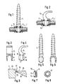
- the holder consists of the threaded rod 1, the nuts 2, 3 and at least one holding part, namely the bone screw 4 or the hook 5.
- the bone screw 4 or the hook 5 are connected to the threaded rod 1 or the nuts 2 by means of the fork head 6 , 3 connected.
- the fork head 6 forms two fork fingers 7, which are connected to one another by the fork web 8, which in turn is connected to the screw part or hook part.
- the fork head 6 has an annular projection 9 running through the fork fingers 7 and the web 8, the outer contour 10 of which is conical with the outer diameter decreasing from the fingers 7.
- the cone angle (measured between two diametrically opposed surface lines) is 60 ° in the example shown and is preferably between 30 and 120 °, preferably between 45 and 90 °.
- the shape shown is generally useful because it ensures a safe "catching" of the projection 9 by the nuts with a comparatively small space requirement even with a relatively large oblique position of the fork head relative to the direction of the threaded rod 1 and at a certain distance of the nuts from the fork head .
- the nuts In their peripheral region 11, the nuts have suitable formations for attacking a key, preferably hexagonal surfaces. In the area 12 they are expediently cylindrical to form the annular collar 13, the inner contour 14 of which is conical in the example shown and corresponds to the conical contour 10 of the clevis protrusions 9. In the assembled state, the configuration shown in FIGS. 1 and 2 results, with play 15 between the interacting conical surfaces is indicated, which is not present in the practical implementation.
- the nuts and the fork head interact via the flat end face 16 of the fork head, which can be expedient for transmitting a bending moment and for the nut fixing explained below can. In other cases, the sole force transmission over the interacting cone surfaces is preferred.
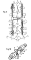
- Fig. 10 which essentially corresponds to the embodiment of FIGS. 1 to 8 and differs therefrom only by the limitation of the projections 9a to the region of the fork head fingers 7, clearly shows that the invention allows the holding part 4 in front of the Contraction of the nuts 2, 3 with respect to the threaded rod 1 is highly misaligned and can nevertheless be correctly grasped by the interaction of the clevis protrusions 9a with the ring collar 13 of the nuts and forced into the desired, rectangular position relative to the threaded rod 1.
- two holders 17, 18 according to the invention are used for distraction of vertebral bodies, wherein they are connected to one another by a web 18 to form an H-frame.
- the annular collar 14 ends in an edge 19 which is thin and can therefore be easily deformed using suitable tools.
- the center line 20 extends from the main body of the nut not only in the axial direction but also obliquely outwards. If a force is now exerted on the edge 19 with the aid of a suitable tool in the direction of the arrow 21, it will bend, as is indicated at 22. As a result of the beveling of the center line 20, the deformation does not only take place radially inwards, but also somewhat in the axial direction.
- the deformation 22 results in a bulge bordered by the edges 23 of the fork fingers 7 or the projections 9, which provides the positive locking of the nut in the position. It is expedient for the fixation that the fork fingers 7 the edge 19 of the ring collar 13 at the point at which the edge 19 over the inner edge of the Fork fingers run away, protrude. However, this is not absolutely necessary, since even a mere deformation radially inwards causes a deformation point which cooperates with a projection, provided that the projection is sufficiently adjacent to the edge in cross section.
Abstract
Description
- Die Erfindung betrifft einen knochenchirurgischen Halter mit einer Gewindestange und einem Halteteil, der einen zwischen einem Mutternpaar an der Gewindestange zu befestigten Gabelkopf aufweist.
- Halter dieser Art werden vornehmlich zur Distraktion und Kontraktion in der Wirbelsäulenchirurgie und bei der internen oder externen Fixation von Knochenfrakturen verwendet. Der Gabelkopf des Halteteils hat oftmals beträchtliche Kräfte aufzunehmen, die dazu zwingen, die Gabelfinger und auch den die Gabelfinger verbindenden Gabelsteg kräftig zu dimensionieren. Jedoch ist man andererseits bestrebt, die Abmessungen von zur zeitweiligen oder dauernden Implantation bestimmten Teilen möglichst gering zu halten. Dabei sollen die Muttern den Gabelkopf während einer gewissen Zeitspanne sicher an der Gewindestange halten, ohne daß sich die Position des Halters gegenüber der Gewindestange verändern kann. Zu diesem Zweck versucht die Erfindung zu erreichen, daß einerseits die Muttern einen hohen Lösewiderstand aufweisen und daß andererseits selbst dann, wenn eine Mutter sich gelockert haben sollte, der winkelfeste Verbund zwischen Halter und Gewindestange nicht gefährdet wird.
- Diese Ziele werden nicht erreicht von bekannten Anordnungen (WO 89/00028 und DE-A 36 39 810), bei denen keine Maßnahmen zur Erhöhung des Lösewiderstands der Muttern getroffen sind und eine Winkelbeweglichkeit des Halters zur Gewindestange bei gelockerten Muttern gegeben ist.
- Die Erfindung erreicht das angegebene Ziel durch die Merkmale des Anspruchs 1.
- Der höhere Lösewiderstand der erfindungsgemäßen Anordnung ergibt sich daraus, daß die Spannkraft der Muttern oder zumindest ein wesentlicher Teil derselben über die flächig konisch aneinander anliegenden Konusflächen der Vorsprünge bzw. Vertiefungen am Gabelkopf bzw. an der Mutter übertragen werden. Während bei einer Kraftübertragungsfläche, die lotrecht zur Kraftübertragungsrichtung verläuft, die mittlere Flächenpressung durch den Quotienten aus der übertragenden Kraft und der Kraftübertragungsfläche bestimmt wird, ist im Falle einer Kraftübertragung über eine Schrägfläche die Flächenpressung um den Faktor 1/sin alpha größer, wobei alpha der Winkel zwischen der Schrägfläche und der Kraftübertragungsrichtung ist. Bei einer Konusfläche gilt diese Beziehung gleichfalls angenähert, wobei alpha der Winkel zwischen einer Mantellinie und der Achse ist. Bei Wahl von alpha gleich 30 Grad wird auf diese Weise die Flächenpressung etwa verdoppelt. Entsprechend erhöht ist auch der Lösewiderstand. Daher besitzt die erfindungsgemäße Anordnung eine wesentlich höhere Sicherheit gegen unbeabsichtigtes Lösen der Muttern als bekannte Anordnungen. Dies gilt auch gegenüber derjenigen bekannten Anordnung (WO 89/00028), bei welcher die Vorsprünge am Gabelkopf und an den Muttern sphärisch ausgebildet sind, weil dort infolge der Verformungsmöglichkeit des Gabelkopfs nach innen von den sphärischen Kraftübertragungsflächen lediglich die Bereiche mit geringstem Neigungswinkel für die Kraftübertragung in Betracht kommen.
- Ferner wird durch die erfindungsgemäßen Merkmale erreicht, daß die winkelfeste Verbindung zwischen dem Halteteil und der Gewindestange selbst dann nicht verloren geht, wenn eine Mutter sich geringfügig lockern sollte, weil dann immer noch der unschwenkbare Eingriff der Konusvorsprünge in des Gabelkopfs in die Konusvertiefungen der Muttern vorhanden ist.
- Wie auch bei den bekannten Anordnungen mit sphärischen Zusammenwirken von Gabelkopf und Muttern, bietet die Erfindung den Vorteil, daß die in den Vertiefungen der Muttern gehaltenen Vorsprünge des Gabelkopfes diesen daran hindern, sich aufzubiegen. Auch wird die Fixierung des Halteteils während der Operation dadurch erleichtert, daß die Muttern schon dann, wenn sie sich dem Gabelkopf eine gewisse Distanz genähert haben, die Vorsprünge des Gabelkopfs umfassen und dadurch Eingriffssicherheit geben. Der Operateur kann anschließend die Muttern zum Justieren oder Aufrichten des Halteteils festziehen, ohne auf dem korrekten Sitz achten zu müssen; denn mit zunehmender Annäherung der Muttern an den Gabelkopf wird dieser aufgerichtet. Nach einem besonderen Merkmal der Erfindung wird die konische Vertiefung der Muttern von einem als dünner Rand auslaufenden Ringkragen gebildet. Dieses Merkmal gibt die Möglichkeit einer einfachen und sicheren Arretierung der Muttern, in dem der Rand im Zwischenraum zwischen den Fingern des Gabelkopfs, vorzugsweise benachbart der Innenkante eines Gabelfingers bzw. des darin gebildeten Vorsprungs, ein wenig eingebeult wird. Sollte sich die Mutter in Löserichtung zu drehen versuchen, schlägt die verformte Stelle des Rands an der Innenkante eines Gabelfingers oder Vorsprungs an, wodurch die weitere Drehung verhindert wird, solange die auf die Mutter wirkenden Drehkräfte eine bestimmte, in der praktischen Anwendung zu erwartende Schwelle nicht überschreiten.
- Ferner kann nach der Erfindung vorgesehen sein, daß der dünne Rand des Ringkragens mit einer an der Gabel den Vorsprung umgebenden Fläche zusammenwirkt, die quer zur Kraftübertragungsrichtung (also in der Regel eben) verläuft. Ein solches Zusammenwirken kann auch dann stattfinden, wenn ein wesentlicher Teil der Kraft über die Konusflächen übertragen wird, weil diese sich unter dieser Kraft ein wenig nach innen verformen und damit dem Rand des Ringkragens die Möglichkeit geben, mit der genannten, dem Konusvorsprung umgebenden Fläche zusammenzuwirken. Dabei verformt sich der dünne Rand des Ringkragens ein wenig, wobei er im Bereich des Zwischenraums des Gabelkopfs ein wenig weiter in Kraftübertragungsrichtung vorragt als an der genannten Fläche. Daraus resultiert ein kräftiger Lösewiderstand selbst dann, wenn der Rand in den Gabelzwischenraum hinein nicht noch gesondert verformt wurde.
- Um aber eine solche, besondere Verformung möglich zu machen, ist eine Mutter nach der Erfindung zweckmäßigerweise mit einem Widerlager für ein entsprechendes Verformungswerkzeug ausgerüstet.
- Die Erfindung wird im folgenden näher unter Bezugnahme auf die Zeichnung erläutert, die vorteilhafte Ausführungsbeispiele veranschaulicht. Darin zeigen:
- Fig. 1
- eine teilweise geschnittene Ansicht des Halters unter Verwendung einer Knochenschraube als Halteteil,
- Fig. 2
- eine der Fig. 1 entsprechende Ansicht unter Verwendung eines Hakens als Halteteil,
- Fig. 3 und 4
- zwei Ansichten des Hakens,
- Fig. 5 und 6
- zwei Ansichten der Knochenschraube,
- Fig. 7 und 8
- zwei Ansichten einer Mutter,
- Fig. 9
- ein Detail im Schnitt
- Fig. 10
- eine perspektivische Ansicht des Halters während der Montage und
- Fig. 11
- ein Anwendungsbeispiel des Halters in der Wirbelsäulenchirurgie.
- Der Halter besteht aus der Gewindestange 1, den Muttern 2, 3 und wenigstens einem Halteteil, nämlich der Knochenschraube 4 bzw. dem Haken 5. Die Knochenschraube 4 bzw. der Haken 5 sind mittels des Gabelkopfs 6 mit der Gewindestange 1 bzw. den Muttern 2, 3 verbunden. Der Gabelkopf 6 bildet zwei Gabelfinger 7, die durch den Gabelsteg 8 miteinander verbunden sind, der seinerseits mit dem Schraubenteil bzw. Hakenteil verbunden ist. Auf beiden Stirnseiten weist der Gabelkopf 6 einen an den Gabelfingern 7 und dem Steg 8 durchlaufenden Ringvorsprung 9 auf, dessen Außenkontur 10 konisch ist mit von den Fingern 7 aus geringer werdendem Außendurchmesser. Der Konuswinkel (gemessen zwischen zwei diametral gegenüberliegenden Mantellinien) beträgt in dem dargestellten Beispiel 60° und liegt vorzugsweise zwischen 30 und 120°, vorzugsweise zwischen 45 und 90°. Es ist nicht erforderlich, daß es sich um eine Kegelform im mathematischen Sinne handelt. Jedoch ist die dargestellte Form im allgemeinen zweckmäßig, weil sie auch bei verhältnismäßig großer Schräglage des Gabelkopfs gegenüber der Richtung der Gewindestange 1 und schon in einer gewissen Entfernung der Muttern vom Gabelkopf ein sicheres "Fangen" des Vorsprungs 9 durch die Muttern bei vergleichsweise geringem Raumbedarf gewährleistet.
- Die Muttern tragen in ihrem Umfangsbereich 11 geeignete Formationen für den Angriff eines Schlüssels, vorzugsweise Sechskantflächen. Im Bereich 12 sind sie zweckmäßigerweise zylindrisch zur Bildung des Ringkragens 13, dessen Innenkontur 14 im dargestellten Beispiel konisch ist und übereinstimmt mit der konischen Kontur 10 der Gabelkopfvorsprünge 9. Im montierten Zustand ergibt sich die in Fig. 1 und 2 dargestellte Konfiguration, wobei Spiel 15 zwischen den zusammenwirkenden Konusflächen angedeutet ist, das bei der praktischen Ausführung nicht vorhanden ist. Außerdem wirken die Muttern und der Gabelkopf über die ebene Stirnfläche 16 des Gabelkopfs zusammen, was zur Übertragung eines Biegemoments sowie zu der weiter unten erläuterten Mutternfixierung zweckmäßig sein kann. In anderen Fällen zieht man die alleinige Kraftübertragung über die zusammenwirkenden Konusflächen vor.
- Fig. 10, die im wesentlichen mit der Ausführung gemäß Fig. 1 bis 8 übereinstimmt und sich davon nur durch die Beschränkung der Vorsprünge 9a auf den Bereich der Gabelkopffinger 7 unterscheidet, zeigt deutlich, daß die Erfindung es gestattet, daß der Halteteil 4 vor dem Zusammenziehen der Muttern 2, 3 gegenüber der Gewindestange 1 in hohem Maße unausgerichtet ist und dennoch durch das Zusammenwirken der Gabelkopfvorsprünge 9a mit dem Ringkragen 13 der Muttern richtig erfaßt und in die gewünschte, rechtwinklige Lage zur Gewindestange 1 gezwungen werden kann.
- In dem Anwendungsbeispiel gemäß Fig. 11 sind zwei erfindungsgemäße Halter 17, 18 zur Distraktion von Wirbelkörpern eingesetzt, wobei sie durch einen Steg 18 miteinander zu einem H-Rahmen verbunden sind.
- Wie man der vergrößerten Darstellung in Fig. 9 entnimmt, läuft der Ringkragen 14 in einem Rand 19 aus, der dünn ist und daher leicht mit geeigneten Werkzeugen verformt werden kann. Die Mittellinie 20 verläuft, vom Hauptkörper der Mutter her, nicht nur in axialer Richtung, sondern auch schräg nach außen. Wird nun mit Hilfe eines geeigneten Werkzeugs in Richtung des Pfeils 21 eine Kraft auf den Rand 19 ausgeübt, so wird er sich verbiegen, wie dies bei 22 angedeutet ist. Infolge der Schrägung der Mittellinie 20 erfolgt die Verformung nicht nur radial nach innen, sondern auch ein wenig in axialer Richtung. Nimmt man diese Verformung zwischen zwei Gabelkopffingern 7 vor, und zwar möglichst benachbart der Innenkante 23 dieser Finger, so erreicht man durch die Verformung 22 eine von den Kanten 23 der Gabelfinger 7 oder der Vorsprünge 9 eingefaßte Einbeulung, die die formschlüssige Sicherung der Mutter in der jeweiligen Stellung bewirkt. Zweckmäßig für die Fixierung ist, daß die Gabelfinger 7 den Rand 19 des Ringkragens 13 an derjenigen Stelle, an der der Rand 19 über die Innenkante der Gabelfinger hinwegläuft, überragen. Jedoch ist das nicht unbedingt erforderlich, da auch schon eine bloße Verformung radial nach innen bewirkt, daß eine mit einem Vorsprung zusammenwirkende Verformungsstelle entsteht, sofern der Vorsprung im Querschnitt dem Rand hinreichend benachbart ist.
Claims (5)
- Knochenchirurgischer Halter mit einer Gewindestange (1) und einem Halteteil (4, 5), der einen zwischen einem Mutternpaar (2, 3) an der Gewindestange (1) zu befestigenden Gabelkopf (6) aufweist, wobei der Gabelkopf konzentrisch zu der vorgesehenen Stangenposition angeordnete Vorsprünge (9) und die Muttern (2, 3) Vertiefungen (14) aufweisen, die mit den Vorsprüngen (9) kraftübertragend zusammenwirken, dadurch gekennzeichnet, daß die Vorsprünge (9) und Vertiefungen (14) konisch ausgebildet sind.
- Halter nach Anspruch 1, dadurch gekennzeichnet, daß die Vorsprünge (9) von einem an den Gabelfingern (7) und dem Gabelsteg (8) durchlaufenden Ringvorsprung gebildet sind.
- Halter nach Anspruch 1 oder 2, dadurch gekennzeichnet, daß die konische Vertiefung (14) der Muttern von einem als dünner Rand (19) auslaufenden Ringkragen (13) gebildet ist.
- Halter nach Anspruch 3, dadurch gekennzeichnet, daß der dünne Rand (19) des Ringkragens (13) mit einer an der Gabel (6) den Vorsprung (9) umgebenden Fläche zusammenwirkt.
- Halter nach Anspruch 3 oder 4, dadurch gekennzeichnet, daß eine Mutter (2, 3) ein Widerlager für ein Werkzeug zum Verformen des Ringkragens (13) aufweist.
Applications Claiming Priority (2)
| Application Number | Priority Date | Filing Date | Title |
|---|---|---|---|
| DE9004240U DE9004240U1 (de) | 1990-04-11 | 1990-04-11 | |
| DE9004240U | 1990-04-11 |
Publications (2)
| Publication Number | Publication Date |
|---|---|
| EP0452792A1 true EP0452792A1 (de) | 1991-10-23 |
| EP0452792B1 EP0452792B1 (de) | 1995-03-01 |
Family
ID=6852861
Family Applications (1)
| Application Number | Title | Priority Date | Filing Date |
|---|---|---|---|
| EP91105668A Expired - Lifetime EP0452792B1 (de) | 1990-04-11 | 1991-04-10 | Knochenchirurgischer Halter |
Country Status (3)
| Country | Link |
|---|---|
| EP (1) | EP0452792B1 (de) |
| DE (2) | DE9004240U1 (de) |
| ES (1) | ES2071148T3 (de) |
Cited By (10)
| Publication number | Priority date | Publication date | Assignee | Title |
|---|---|---|---|---|
| FR2684866A1 (fr) * | 1991-12-12 | 1993-06-18 | Jbs Sa | Perfectionnements aux procedes et aux dispositifs de redressement, fixation, compression, elongation du rachis. |
| EP0558883A1 (de) * | 1992-03-02 | 1993-09-08 | Howmedica GmbH | Vorrichtung zum Verspannen von Wirbeln der menschlichen Wirbelsäule |
| US5275600A (en) * | 1992-10-05 | 1994-01-04 | Zimmer, Inc. | Telescoping rod to rod coupler for a spinal system |
| WO1994006361A2 (en) * | 1992-09-10 | 1994-03-31 | H.D. Medical, Inc. | System and method for stabilizing bone segments |
| WO1994017745A1 (de) * | 1993-02-09 | 1994-08-18 | Plus Endoprothetik Ag | Vorrichtung zur wirbelsäulen-versteifung und/oder -korrektur |
| DE4316541C1 (de) * | 1993-05-18 | 1994-08-18 | Schaefer Micomed Gmbh | Knochenchirurgische Haltevorrichtung |
| EP0671151A1 (de) * | 1994-03-10 | 1995-09-13 | Schäfer micomed GmbH | Osteosynthesevorrichtung |
| FR2718945A1 (fr) * | 1994-04-25 | 1995-10-27 | Soprane Sa | Dispositif de retenue d'une tige de liaison d'un fixateur de rachis sur une vis pédiculaire. |
| EP1101449A1 (de) | 1994-06-04 | 2001-05-23 | Howmedica GmbH | Vorrichtung zum Stabilisieren bzw. Komprimieren oder Distrahieren von Abschnitten der Wirbelsäule |
| CN100376219C (zh) * | 1998-07-06 | 2008-03-26 | 株式会社率高 | 脊椎固定装置 |
Families Citing this family (6)
| Publication number | Priority date | Publication date | Assignee | Title |
|---|---|---|---|---|
| CH686610A5 (de) * | 1991-10-18 | 1996-05-15 | Pina Vertriebs Ag | Kompressionsimplantat. |
| WO1993021847A1 (en) * | 1992-04-29 | 1993-11-11 | Danek Medical, Inc. | Positionable spinal fixation device |
| DE4316543C1 (de) * | 1993-05-18 | 1994-07-21 | Schaefer Micomed Gmbh | Knochenchirurgische Haltevorrichtung |
| DE4316542C1 (de) * | 1993-05-18 | 1994-07-21 | Schaefer Micomed Gmbh | Osteosynthesevorrichtung |
| DE19835816C2 (de) * | 1998-08-08 | 2002-02-07 | Schaefer Micomed Gmbh | Osteosynthesevorrichtung |
| DE19951145C2 (de) * | 1999-10-23 | 2003-11-13 | Schaefer Micomed Gmbh | Osteosynthesevorrichtung |
Citations (5)
| Publication number | Priority date | Publication date | Assignee | Title |
|---|---|---|---|---|
| BE496725A (de) * | ||||
| GB2041139A (en) * | 1979-02-07 | 1980-09-03 | Radisic B | Locking of nuts |
| DE3639810A1 (de) * | 1986-11-21 | 1988-05-26 | Heinrich Ulrich | Implantat zur wirbelsaeulenkorrektur und/oder -stabilisierung |
| WO1989000028A1 (en) * | 1987-07-08 | 1989-01-12 | Lutz Biedermann | Positioning device |
| WO1991001115A1 (de) * | 1989-07-20 | 1991-02-07 | Lutz Biedermann | Aufnahmeteil für eine pedikelschraube und pedikelschraube |
-
1990
- 1990-04-11 DE DE9004240U patent/DE9004240U1/de not_active Expired - Lifetime
-
1991
- 1991-04-10 ES ES91105668T patent/ES2071148T3/es not_active Expired - Lifetime
- 1991-04-10 EP EP91105668A patent/EP0452792B1/de not_active Expired - Lifetime
- 1991-04-10 DE DE59104736T patent/DE59104736D1/de not_active Expired - Fee Related
Patent Citations (5)
| Publication number | Priority date | Publication date | Assignee | Title |
|---|---|---|---|---|
| BE496725A (de) * | ||||
| GB2041139A (en) * | 1979-02-07 | 1980-09-03 | Radisic B | Locking of nuts |
| DE3639810A1 (de) * | 1986-11-21 | 1988-05-26 | Heinrich Ulrich | Implantat zur wirbelsaeulenkorrektur und/oder -stabilisierung |
| WO1989000028A1 (en) * | 1987-07-08 | 1989-01-12 | Lutz Biedermann | Positioning device |
| WO1991001115A1 (de) * | 1989-07-20 | 1991-02-07 | Lutz Biedermann | Aufnahmeteil für eine pedikelschraube und pedikelschraube |
Cited By (20)
| Publication number | Priority date | Publication date | Assignee | Title |
|---|---|---|---|---|
| WO1993011715A1 (fr) * | 1991-12-12 | 1993-06-24 | Jbs Sa | Perfectionnements aux procedes et aux dispositifs de redressement, fixation, compression, elongation du rachis |
| FR2684866A1 (fr) * | 1991-12-12 | 1993-06-18 | Jbs Sa | Perfectionnements aux procedes et aux dispositifs de redressement, fixation, compression, elongation du rachis. |
| US6261287B1 (en) | 1992-03-02 | 2001-07-17 | Stryker Trauma Gmbh | Apparatus for bracing vertebrae |
| EP0558883A1 (de) * | 1992-03-02 | 1993-09-08 | Howmedica GmbH | Vorrichtung zum Verspannen von Wirbeln der menschlichen Wirbelsäule |
| US8007520B2 (en) | 1992-03-02 | 2011-08-30 | Stryker Trauma Gmbh | Apparatus for bracing vertebrae |
| US7988713B2 (en) | 1992-03-02 | 2011-08-02 | Stryker Trauma Gmbh | Apparatus for bracing vertebrae |
| US7128743B2 (en) | 1992-03-02 | 2006-10-31 | Stryker Trauma Gmbh | Apparatus for bracing vertebrae |
| WO1994006361A3 (en) * | 1992-09-10 | 1994-05-26 | H.D. Medical, Inc. | System and method for stabilizing bone segments |
| US5382248A (en) * | 1992-09-10 | 1995-01-17 | H. D. Medical, Inc. | System and method for stabilizing bone segments |
| WO1994006361A2 (en) * | 1992-09-10 | 1994-03-31 | H.D. Medical, Inc. | System and method for stabilizing bone segments |
| AU665673B2 (en) * | 1992-10-05 | 1996-01-11 | Bristol-Myers Squibb Company | Telescopic rod to rod coupler for a spinal system |
| US5275600A (en) * | 1992-10-05 | 1994-01-04 | Zimmer, Inc. | Telescoping rod to rod coupler for a spinal system |
| US5562660A (en) * | 1993-02-09 | 1996-10-08 | Plus Endoprothetik Ag | Apparatus for stiffening and/or correcting the vertebral column |
| WO1994017745A1 (de) * | 1993-02-09 | 1994-08-18 | Plus Endoprothetik Ag | Vorrichtung zur wirbelsäulen-versteifung und/oder -korrektur |
| DE4316541C1 (de) * | 1993-05-18 | 1994-08-18 | Schaefer Micomed Gmbh | Knochenchirurgische Haltevorrichtung |
| EP0671151A1 (de) * | 1994-03-10 | 1995-09-13 | Schäfer micomed GmbH | Osteosynthesevorrichtung |
| FR2718945A1 (fr) * | 1994-04-25 | 1995-10-27 | Soprane Sa | Dispositif de retenue d'une tige de liaison d'un fixateur de rachis sur une vis pédiculaire. |
| EP0679369A1 (de) * | 1994-04-25 | 1995-11-02 | Societe De Fabrication De Materiel Orthopedique Sofamor | Vorrichtung zur Befestigung eines spinalen Verbindungsstabes an einer Pedikelschraube |
| EP1101449A1 (de) | 1994-06-04 | 2001-05-23 | Howmedica GmbH | Vorrichtung zum Stabilisieren bzw. Komprimieren oder Distrahieren von Abschnitten der Wirbelsäule |
| CN100376219C (zh) * | 1998-07-06 | 2008-03-26 | 株式会社率高 | 脊椎固定装置 |
Also Published As
| Publication number | Publication date |
|---|---|
| EP0452792B1 (de) | 1995-03-01 |
| DE59104736D1 (de) | 1995-04-06 |
| ES2071148T3 (es) | 1995-06-16 |
| DE9004240U1 (de) | 1991-08-08 |
Similar Documents
| Publication | Publication Date | Title |
|---|---|---|
| EP3117787B1 (de) | Pedikelschraube mit tulpe | |
| EP1579817B1 (de) | Schraubendreher für Knochenschrauben | |
| DE60015636T2 (de) | Kompressionsknochenschraube und Hilfsinstrumente zu ihrer Befestigung | |
| EP1440664B1 (de) | Implantat für Osteosynthese | |
| EP1608278B1 (de) | Aufnahme für ein verblockungselement und verblockungselement | |
| EP0452792B1 (de) | Knochenchirurgischer Halter | |
| DE69813807T2 (de) | Implantat als platzhalter zwischen wirbelkörpern | |
| DE19851370C2 (de) | Endoskopisches Einsetzinstrumentarium | |
| DE10065398C2 (de) | Längenverstellbarer Platzhalter zum Einsetzen zwischen zwei Wirbelkörper | |
| DE4425357C2 (de) | Verankerungselement | |
| DE69729387T2 (de) | Mehrachsige knochenschraubeanordnung | |
| DE60024798T2 (de) | Anordnung zum anbringen eines abstandselementes an einem implantat mittels einer schraube | |
| EP1277444A2 (de) | Gewindebolzen, Gewindemutterabschnitt und Gewindeverbindung | |
| EP0988833B1 (de) | Osteosyntheseplatte mit mehreren Knochenschrauben | |
| DE102016108504A1 (de) | Medizintechnisches Instrument zur provisorischen Fixierung einer polyaxialen Pedikelschraube | |
| WO1994026194A1 (de) | Knochenchirurgische haltevorrichtung | |
| EP0671151A1 (de) | Osteosynthesevorrichtung | |
| WO2005041796A1 (de) | Knochenplatte | |
| DE69815166T2 (de) | Trennbare Vorrichtung für eine Knochenplatte oder zur Fixierung zweier Knochenfragmente | |
| EP2976031A1 (de) | Wirbelsäulenstabilisierungssystem und chirurgisches befestigungselement für ein wirbelsäulenstabilisierungssystem | |
| EP1545357B1 (de) | System für die osteosynthese | |
| EP0539536B1 (de) | Schraubeneinheit | |
| EP1539006B1 (de) | Intramedullärer osteosynthese-nagel zum versorgen von röhrenknochenfrakturen | |
| EP1364621B1 (de) | Vorrichtung zum Positionieren und Fixieren von Knochen und/oder Knochenfragmenten | |
| EP2436325B1 (de) | Wirbelsäulenimplantat zur Stabilisierung und Versteifung von Wirbelkörpern |
Legal Events
| Date | Code | Title | Description |
|---|---|---|---|
| PUAI | Public reference made under article 153(3) epc to a published international application that has entered the european phase |
Free format text: ORIGINAL CODE: 0009012 |
|
| AK | Designated contracting states |
Kind code of ref document: A1 Designated state(s): CH DE ES FR GB IT LI NL SE |
|
| 17P | Request for examination filed |
Effective date: 19911018 |
|
| 17Q | First examination report despatched |
Effective date: 19940428 |
|
| GRAA | (expected) grant |
Free format text: ORIGINAL CODE: 0009210 |
|
| AK | Designated contracting states |
Kind code of ref document: B1 Designated state(s): CH DE ES FR GB IT LI NL SE |
|
| REF | Corresponds to: |
Ref document number: 59104736 Country of ref document: DE Date of ref document: 19950406 |
|
| ITF | It: translation for a ep patent filed |
Owner name: UFFICIO TECNICO ING. A. MANNUCCI |
|
| ET | Fr: translation filed | ||
| REG | Reference to a national code |
Ref country code: ES Ref legal event code: FG2A Ref document number: 2071148 Country of ref document: ES Kind code of ref document: T3 |
|
| GBT | Gb: translation of ep patent filed (gb section 77(6)(a)/1977) |
Effective date: 19950612 |
|
| PLBE | No opposition filed within time limit |
Free format text: ORIGINAL CODE: 0009261 |
|
| STAA | Information on the status of an ep patent application or granted ep patent |
Free format text: STATUS: NO OPPOSITION FILED WITHIN TIME LIMIT |
|
| 26N | No opposition filed | ||
| REG | Reference to a national code |
Ref country code: GB Ref legal event code: IF02 |
|
| PGFP | Annual fee paid to national office [announced via postgrant information from national office to epo] |
Ref country code: GB Payment date: 20050331 Year of fee payment: 15 |
|
| PGFP | Annual fee paid to national office [announced via postgrant information from national office to epo] |
Ref country code: NL Payment date: 20050418 Year of fee payment: 15 |
|
| PGFP | Annual fee paid to national office [announced via postgrant information from national office to epo] |
Ref country code: FR Payment date: 20050419 Year of fee payment: 15 |
|
| PGFP | Annual fee paid to national office [announced via postgrant information from national office to epo] |
Ref country code: ES Payment date: 20050421 Year of fee payment: 15 |
|
| PGFP | Annual fee paid to national office [announced via postgrant information from national office to epo] |
Ref country code: SE Payment date: 20050422 Year of fee payment: 15 Ref country code: CH Payment date: 20050422 Year of fee payment: 15 |
|
| PGFP | Annual fee paid to national office [announced via postgrant information from national office to epo] |
Ref country code: DE Payment date: 20050621 Year of fee payment: 15 |
|
| PG25 | Lapsed in a contracting state [announced via postgrant information from national office to epo] |
Ref country code: GB Free format text: LAPSE BECAUSE OF NON-PAYMENT OF DUE FEES Effective date: 20060410 |
|
| PG25 | Lapsed in a contracting state [announced via postgrant information from national office to epo] |
Ref country code: SE Free format text: LAPSE BECAUSE OF NON-PAYMENT OF DUE FEES Effective date: 20060411 Ref country code: ES Free format text: LAPSE BECAUSE OF NON-PAYMENT OF DUE FEES Effective date: 20060411 |
|
| PG25 | Lapsed in a contracting state [announced via postgrant information from national office to epo] |
Ref country code: LI Free format text: LAPSE BECAUSE OF NON-PAYMENT OF DUE FEES Effective date: 20060430 Ref country code: CH Free format text: LAPSE BECAUSE OF NON-PAYMENT OF DUE FEES Effective date: 20060430 |
|
| PGFP | Annual fee paid to national office [announced via postgrant information from national office to epo] |
Ref country code: IT Payment date: 20060430 Year of fee payment: 16 |
|
| PG25 | Lapsed in a contracting state [announced via postgrant information from national office to epo] |
Ref country code: NL Free format text: LAPSE BECAUSE OF NON-PAYMENT OF DUE FEES Effective date: 20061101 Ref country code: DE Free format text: LAPSE BECAUSE OF NON-PAYMENT OF DUE FEES Effective date: 20061101 |
|
| REG | Reference to a national code |
Ref country code: CH Ref legal event code: PL |
|
| EUG | Se: european patent has lapsed | ||
| GBPC | Gb: european patent ceased through non-payment of renewal fee |
Effective date: 20060410 |
|
| NLV4 | Nl: lapsed or anulled due to non-payment of the annual fee |
Effective date: 20061101 |
|
| REG | Reference to a national code |
Ref country code: FR Ref legal event code: ST Effective date: 20061230 |
|
| REG | Reference to a national code |
Ref country code: ES Ref legal event code: FD2A Effective date: 20060411 |
|
| PG25 | Lapsed in a contracting state [announced via postgrant information from national office to epo] |
Ref country code: FR Free format text: LAPSE BECAUSE OF NON-PAYMENT OF DUE FEES Effective date: 20060502 |
|
| PG25 | Lapsed in a contracting state [announced via postgrant information from national office to epo] |
Ref country code: IT Free format text: LAPSE BECAUSE OF NON-PAYMENT OF DUE FEES Effective date: 20070410 |