EP0452530A1 - Dispositif de mélange - Google Patents
Dispositif de mélange Download PDFInfo
- Publication number
- EP0452530A1 EP0452530A1 EP90107519A EP90107519A EP0452530A1 EP 0452530 A1 EP0452530 A1 EP 0452530A1 EP 90107519 A EP90107519 A EP 90107519A EP 90107519 A EP90107519 A EP 90107519A EP 0452530 A1 EP0452530 A1 EP 0452530A1
- Authority
- EP
- European Patent Office
- Prior art keywords
- component
- rotor
- mixing substances
- rotation
- housing
- Prior art date
- Legal status (The legal status is an assumption and is not a legal conclusion. Google has not performed a legal analysis and makes no representation as to the accuracy of the status listed.)
- Withdrawn
Links
Images
Classifications
-
- B—PERFORMING OPERATIONS; TRANSPORTING
- B01—PHYSICAL OR CHEMICAL PROCESSES OR APPARATUS IN GENERAL
- B01F—MIXING, e.g. DISSOLVING, EMULSIFYING OR DISPERSING
- B01F25/00—Flow mixers; Mixers for falling materials, e.g. solid particles
- B01F25/70—Spray-mixers, e.g. for mixing intersecting sheets of material
- B01F25/74—Spray-mixers, e.g. for mixing intersecting sheets of material with rotating parts, e.g. discs
-
- Y—GENERAL TAGGING OF NEW TECHNOLOGICAL DEVELOPMENTS; GENERAL TAGGING OF CROSS-SECTIONAL TECHNOLOGIES SPANNING OVER SEVERAL SECTIONS OF THE IPC; TECHNICAL SUBJECTS COVERED BY FORMER USPC CROSS-REFERENCE ART COLLECTIONS [XRACs] AND DIGESTS
- Y10—TECHNICAL SUBJECTS COVERED BY FORMER USPC
- Y10S—TECHNICAL SUBJECTS COVERED BY FORMER USPC CROSS-REFERENCE ART COLLECTIONS [XRACs] AND DIGESTS
- Y10S366/00—Agitating
- Y10S366/601—Motor control
Definitions
- the invention relates to a method for mixing substances, wherein a first component, in particular bulk material, is to be introduced in a metered manner at a lower pressure into a second component which is under higher pressure, in particular a liquid.
- the object of the invention is to provide a method and a device which make it possible to mix a component with a lower pressure with a component under a higher pressure.
- the metered admixing of bulk goods into a liquid component should be made possible as a continuous process.
- the procedural task is solved in that the second component subjected to the higher pressure is subjected to such acceleration by rotation that the pressure difference to the first component is largely compensated for.
- the pressure in the center is reduced to such an extent that another component, such as, for example, powdery bulk goods, can be added in a metered manner.
- the kinetic energy contained in the rotation can advantageously be recovered in a diffuser by increasing the pressure, so that the method requires less energy.
- the rotation can also be generated by suitable guidance of the component flowing in under pressure.
- the rotating bodies can have different angular velocities.
- the measure also has the same purpose if the first component is added to one or more of the rotating bodies.
- the measure contributes that the second component is fed tangentially to the rotation, in particular in the direction of the rotation.
- Dosing tasks in continuous processes can be solved particularly simply and effectively in that the rotating bodies are at a distance from a second or from the housing, which is regulated depending on at least one component flow and / or depending on the pressure difference.
- the operational reliability of the method is increased by regulating the rotation as a function of the pressure difference. Even with pressure fluctuations, the second component does not pass into the feed line of the first component.
- a device for mixing substances is suitable for carrying out the method, a first component, in particular bulk material, to be introduced in a metered manner at a lower pressure into a second component which is under higher pressure, in particular a liquid, with a housing into which an inlet line opens out for the second component, an admixing line for the first component and an outlet line for the mixed product, at least one preferably plate-shaped rotor being arranged in the housing.
- the rotor rotates at an angular speed which corresponds approximately to the rotation of the second component. It supports the addition and distribution of the first component to be mixed. It is also possible to arrange a plurality of rotors which, for example, form a number of rotating circular gap openings in the form of plates, through which the first component to be mixed is introduced into the second.
- An energy loss of the device can advantageously be reduced if the feed line of the second component has an axis which is arranged tangentially entering the housing, in particular in the direction of rotation of the rotor.
- the supply of the first component to be mixed can be solved particularly favorably if the admixing line of the first component has an axis which is arranged parallel to the direction of the axis of rotation of the rotor.
- the device can be adapted to changing operating conditions in continuous processes in a particularly simple and reliable manner if a distance control of the rotor to the housing and / or to further rotors and / or a speed control of at least one rotor is provided.
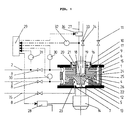
- Numeral 1 denotes a rotationally symmetrical housing, into which an inlet line 2 opens laterally and from which an outlet line 3 leads out.
- the cylindrical middle part 4 of the housing 1 is closed at the bottom by a base plate 5 and at the top by the head plate 6.
- a drain opening 7 In the base plate 5 there is a drain opening 7 to which a drain line with valve 8 connects.
- a vent opening 9 with a vent line 10 and a vent valve 11 is provided in the top plate 6.
- a plate-shaped rotor 12 is rotatably arranged, which is mounted in the base plate 5 (not shown) and is fixedly connected to the rotor of the motor 14 via shaft 13.
- the rotor 12 is opposite a second rotor 15, which is sealed with a seal 16 to the pipe socket 17.
- Pipe socket 17 is firmly connected to the head plate 6.
- the rotor 15 has a central opening 18 which is provided with an internal thread. With the help of this internal thread, the second rotor 15 is screwed onto the pipe section 19, which carries a corresponding external thread.
- a clamping plate 20 is also arranged on the external thread of the pipe section 19 by means of a corresponding internal thread.
- the clamping plate 20 has circular holes for clamping screws 21, of which only the axes are shown in dash-dot lines. These screws engage in corresponding threaded holes in the second rotor 15. By tightening the tensioning screws, the rotor 15 is thus firmly clamped in a fluid manner on the pipe section 19.
- the connecting webs 22 provided between the pipe section 17 and the lower rotor 12 join the lower rotor 12, the pipe section 19, the second rotor 15 and the clamping plate 20 to form a rotating unit 23.
- annular space 24 is formed, which is connected to the interior of the tube piece 19 via the gap 25 formed by the two rotors 12 and 15 and the openings 26 remaining between the webs 22 is.
- a mixing line 27 is arranged opening into the pipe section 19.
- both lines are shown opening at right angles into the cylindrical middle part 4, but both lines can also be advantageous be connected tangentially to the housing 1. If, as in this example, the rotors are driven, the tangential arrangement of the inlet supports the suction effect of the rotors due to the entrainment effect, while the tangential arrangement of the outlet promotes the pressure build-up downstream.
- a frequency converter 28 is provided for the energy supply of the rotor, which makes it possible to regulate the speed of the motor via controller 29.
- the input signals to the controller are the measurement signals of the pressure transmitters 30 in the inlet and outlet lines and the signal of the flow meter 31 in the inlet line 2. Together with the flow meter 32 in the admixing line 27, the mixture ratio of the two components can be kept constant after inputting a corresponding setpoint the controller 29 influences the metering element 36 of the admixing line 27 accordingly.
- the speed of the motor is preferably regulated as a function of the pressure difference between the pressure in the interior of the pipe section 19 and the inlet or outlet line 2, 3. As a result, the position of the liquid boundary layer which forms between the rotors 15 and 12 is kept largely constant.
- the connecting web 22 can be omitted, so that the second rotor is either dragged by the liquid film forming on rotor 12.
- a separate drive can also be provided for the second rotor 15.
- a metered flow of the first component is fed to the pipe section 19 through admixing line 27, for example by means of a screw conveyor or a regulated vibrating trough.
- the second component enters the annular space 24 through the feed line 2 and is partially carried along by the rotating assembly 23 due to its viscosity.
- the second component tries to flow through the gap 25 in the direction of the admixing line 27.
- such a rotation is impressed on it that the resulting centrifugal force compensates for the pressure difference, so that a defined interface is formed in the gap 25, through which the first component can be metered in.
Landscapes
- Chemical & Material Sciences (AREA)
- Chemical Kinetics & Catalysis (AREA)
- Mixers Of The Rotary Stirring Type (AREA)
Priority Applications (2)
| Application Number | Priority Date | Filing Date | Title |
|---|---|---|---|
| EP90107519A EP0452530A1 (fr) | 1990-04-20 | 1990-04-20 | Dispositif de mélange |
| US07/529,904 US5071257A (en) | 1990-04-20 | 1990-05-29 | Method of and arrangement for mixing |
Applications Claiming Priority (1)
| Application Number | Priority Date | Filing Date | Title |
|---|---|---|---|
| EP90107519A EP0452530A1 (fr) | 1990-04-20 | 1990-04-20 | Dispositif de mélange |
Publications (1)
| Publication Number | Publication Date |
|---|---|
| EP0452530A1 true EP0452530A1 (fr) | 1991-10-23 |
Family
ID=8203894
Family Applications (1)
| Application Number | Title | Priority Date | Filing Date |
|---|---|---|---|
| EP90107519A Withdrawn EP0452530A1 (fr) | 1990-04-20 | 1990-04-20 | Dispositif de mélange |
Country Status (2)
| Country | Link |
|---|---|
| US (1) | US5071257A (fr) |
| EP (1) | EP0452530A1 (fr) |
Cited By (2)
| Publication number | Priority date | Publication date | Assignee | Title |
|---|---|---|---|---|
| DE102007025832A1 (de) * | 2006-06-03 | 2007-12-27 | Frymakoruma Ag | Homogenisator-Vorrichtung mit horizontal gelagerten Zahnkränzen |
| CN111097299A (zh) * | 2019-12-26 | 2020-05-05 | 煤科院节能技术有限公司 | 一种调压混合器 |
Families Citing this family (14)
| Publication number | Priority date | Publication date | Assignee | Title |
|---|---|---|---|---|
| US6376558B1 (en) * | 2000-01-06 | 2002-04-23 | Babcock-Bsh Gmbh | Method of producing a porous paste, especially a porous plaster slurry, and a mixer for preparing such paste or slurry |
| AT414101B (de) * | 2000-01-31 | 2006-09-15 | Stelzer C Ekkehard Dr | Verfahren und vorrichtung zum mischen fliessfähiger stoffe |
| US6494609B1 (en) * | 2001-07-16 | 2002-12-17 | United States Gypsum Company | Slurry mixer outlet |
| US7048432B2 (en) * | 2003-06-19 | 2006-05-23 | Halliburton Energy Services, Inc. | Method and apparatus for hydrating a gel for use in a subterranean formation |
| US20060243171A1 (en) * | 2005-04-27 | 2006-11-02 | United States Gypsum Company | Wet gypsum accelerator and methods, composition, and product relating thereto |
| US7718019B2 (en) * | 2005-04-27 | 2010-05-18 | United States Gypsum Company | Methods of and systems for preparing a heat resistant accelerant slurry and adding the accelerant slurry to a post-mixer aqueous dispersion of calcined gypsum |
| US8016960B2 (en) * | 2005-04-27 | 2011-09-13 | United States Gypsum Company | Methods of and systems for adding a high viscosity gypsum additive to a post-mixer aqueous dispersion of calcined gypsum |
| US8240908B2 (en) * | 2005-09-01 | 2012-08-14 | The Procter & Gamble Company | Control system for and method of combining materials |
| US20070047384A1 (en) * | 2005-09-01 | 2007-03-01 | Mclaughlin Jon K | Control system for and method of combining materials |
| US20080031085A1 (en) * | 2005-09-01 | 2008-02-07 | Mclaughlin Jon K | Control system for and method of combining materials |
| US8616760B2 (en) * | 2005-09-01 | 2013-12-31 | The Procter & Gamble Company | Control system for and method of combining materials |
| US20090323458A1 (en) * | 2006-04-11 | 2009-12-31 | Wolfgang Fischer | Continuous process for performing a chemical reaction in which a gaseous phase is added to a charge system comprising one or more solid phases which have been dissolved or dispersed in water |
| JP2009226261A (ja) * | 2008-03-19 | 2009-10-08 | Fujifilm Corp | 液体混合方法および液体混合装置 |
| US10537863B2 (en) | 2015-12-31 | 2020-01-21 | United States Gypsum Company | Constrictor valve with webbing, cementitious slurry mixing and dispensing assembly, and method for making cementitious product |
Citations (9)
| Publication number | Priority date | Publication date | Assignee | Title |
|---|---|---|---|---|
| US3326536A (en) * | 1962-05-09 | 1967-06-20 | Dow Chemical Co | Mixing apparatus |
| DE2241113A1 (de) * | 1972-08-22 | 1974-02-28 | Polysius Ag | Vorrichtung zum einfuehren eines festen, fluessigen oder gasfoermigen stoffes in einen bewegten materialstrom mit einer duese |
| US3850643A (en) * | 1971-07-28 | 1974-11-26 | Eastman Kodak Co | Process for making coupler dispersions |
| US3920225A (en) * | 1974-10-01 | 1975-11-18 | Raymond Lee Organization Inc | Centrifugal chemical mixer |
| WO1981003143A1 (fr) * | 1980-04-28 | 1981-11-12 | J Arribau | Appareil melangeur |
| US4460276A (en) * | 1982-08-16 | 1984-07-17 | Geo Condor, Inc. | Open inlet blender |
| US4690834A (en) * | 1985-02-04 | 1987-09-01 | Appelgren Curt H | Process for coating solid particles |
| EP0241056A1 (fr) * | 1986-03-27 | 1987-10-14 | Compagnie Des Services Dowell Schlumberger | Mélangeurs pour des matériaux pulvérulents et liquides ou des matériaux liquide-liquide |
| US4808004A (en) * | 1988-05-05 | 1989-02-28 | Dowell Schlumberger Incorporated | Mixing apparatus |
Family Cites Families (4)
| Publication number | Priority date | Publication date | Assignee | Title |
|---|---|---|---|---|
| US4329066A (en) * | 1980-09-22 | 1982-05-11 | Nemo Ivarson | Method and apparatus for continuously mixing a liquid and powder |
| US4614435A (en) * | 1985-03-21 | 1986-09-30 | Dowell Schlumberger Incorporated | Machine for mixing solid particles with a fluid composition |
| EP0223907B1 (fr) * | 1985-11-28 | 1991-08-07 | Matsushita Electric Industrial Co., Ltd. | Appareil pour mélanger des fluides multiples |
| US4884893A (en) * | 1987-07-10 | 1989-12-05 | Gaston County Dyeing Machine Co. | Method and apparatus for generating and dispersing immiscible liquid particles in a carrier liquid and dispensing said carrier liquid |
-
1990
- 1990-04-20 EP EP90107519A patent/EP0452530A1/fr not_active Withdrawn
- 1990-05-29 US US07/529,904 patent/US5071257A/en not_active Expired - Lifetime
Patent Citations (9)
| Publication number | Priority date | Publication date | Assignee | Title |
|---|---|---|---|---|
| US3326536A (en) * | 1962-05-09 | 1967-06-20 | Dow Chemical Co | Mixing apparatus |
| US3850643A (en) * | 1971-07-28 | 1974-11-26 | Eastman Kodak Co | Process for making coupler dispersions |
| DE2241113A1 (de) * | 1972-08-22 | 1974-02-28 | Polysius Ag | Vorrichtung zum einfuehren eines festen, fluessigen oder gasfoermigen stoffes in einen bewegten materialstrom mit einer duese |
| US3920225A (en) * | 1974-10-01 | 1975-11-18 | Raymond Lee Organization Inc | Centrifugal chemical mixer |
| WO1981003143A1 (fr) * | 1980-04-28 | 1981-11-12 | J Arribau | Appareil melangeur |
| US4460276A (en) * | 1982-08-16 | 1984-07-17 | Geo Condor, Inc. | Open inlet blender |
| US4690834A (en) * | 1985-02-04 | 1987-09-01 | Appelgren Curt H | Process for coating solid particles |
| EP0241056A1 (fr) * | 1986-03-27 | 1987-10-14 | Compagnie Des Services Dowell Schlumberger | Mélangeurs pour des matériaux pulvérulents et liquides ou des matériaux liquide-liquide |
| US4808004A (en) * | 1988-05-05 | 1989-02-28 | Dowell Schlumberger Incorporated | Mixing apparatus |
Cited By (3)
| Publication number | Priority date | Publication date | Assignee | Title |
|---|---|---|---|---|
| DE102007025832A1 (de) * | 2006-06-03 | 2007-12-27 | Frymakoruma Ag | Homogenisator-Vorrichtung mit horizontal gelagerten Zahnkränzen |
| DE102007025832B4 (de) * | 2006-06-03 | 2016-01-14 | Frymakoruma Ag | Homogenisator-Vorrichtung mit horizontal gelagerten Zahnkränzen |
| CN111097299A (zh) * | 2019-12-26 | 2020-05-05 | 煤科院节能技术有限公司 | 一种调压混合器 |
Also Published As
| Publication number | Publication date |
|---|---|
| US5071257A (en) | 1991-12-10 |
Similar Documents
| Publication | Publication Date | Title |
|---|---|---|
| EP0452530A1 (fr) | Dispositif de mélange | |
| DE2838897C2 (fr) | ||
| CH663376A5 (de) | Verfahren zum beleimen von holz-spaenen mit fluessigleim und vorrichtung zur durchfuehrung des verfahrens. | |
| WO1995015209A1 (fr) | Procede et dispositif de concentration de melanges solides/liquides selon une technologie faisant appel a des membranes | |
| DE69704143T2 (de) | Dosierungsförderschnecke mit mehreren eingeschnittenen Schneckengängen | |
| WO1992021436A1 (fr) | Dispositif de dispersion, suspension ou emulsion de gaz, liquides et/ou matieres solides coulantes | |
| DE2453810A1 (de) | Verfahren und vorrichtung zum dispergieren eines pulvers in einer fluessigkeit | |
| EP0029165A2 (fr) | Installation pour la fabrication en continu d'un lait d'amidon | |
| WO2007045589A1 (fr) | Dispositif pour appliquer en nappe une matiere a deux composants sur un support | |
| DE2236200C3 (de) | GieBerefmischmaschine zum Mischen eines körnigen oder pulverförmigen Formmaterials mit flüssigem Binder | |
| DE19911492A1 (de) | Vorrichtung und Verfahren zur Entgasung eines Fluids | |
| DE2438818A1 (de) | Vorrichtung zum kontinuierlichen beleimen von fasern | |
| DE2108181A1 (de) | Verfahren und Vorrichtung zum kontinuierlichen Aufbereiten von körnigem Material, beispielsweise Giessereisand | |
| DE2701508C3 (de) | Verfahren zur Regelung des Mischungsverhältnisses einer zu fördernden Mischung aus körnigem oder pulverförmigen Trockengut und einer Flüssigkeit und Vorrichtung zur Durchführung des Verfahrens | |
| EP3953029B1 (fr) | Procédé permettent de vider un dispositif de fabrication de granulats ou de produits extrudés | |
| DE2511971C3 (de) | Verfahren zum Herstellen von Zusatzstoffe enthaltenden Polyvinylchlorid-Mischungen | |
| DE3703132C1 (de) | Vorrichtung zum Auftragen eines fliessfaehigen,Schaumstoff bildenden Reaktionsgemisches auf eine Unterlage zum Herstellen von Schaumstoffbahnen oder-platten | |
| DE2631622A1 (de) | Verfahren und vorrichtung zum gleichzeitigen und kontinuierlichen zufuehren von pulverfoermigen feststoffen und fluessigkeiten in behandlungsmaschinen | |
| DE10010287B4 (de) | Verfahren zur Herstellung von flüssigen Gemischen für das chemisch-mechanische Polieren von Wafern | |
| DE69906133T2 (de) | Gerät und verfahren zum kontinuierlichen mischen | |
| DE2701305C2 (de) | Vorrichtung zur flotativen Aufbereitung von Feststoffen | |
| EP0162357B1 (fr) | Dispositif d'addition d'un premier produit granulé à un deuxième produit granulé | |
| EP3953028B1 (fr) | Dispositif de fabrication de granulats ou de produits extrudés | |
| DE20009961U1 (de) | Dosierreaktor für die Aufbereitung von Rohwasser und Anlage für die Aufbereitung von Trinkwasser | |
| DE4133604C2 (de) | Vorrichtung zum Fördern und Mischen eines Feststoffes mit einer Flüssigkeit |
Legal Events
| Date | Code | Title | Description |
|---|---|---|---|
| PUAI | Public reference made under article 153(3) epc to a published international application that has entered the european phase |
Free format text: ORIGINAL CODE: 0009012 |
|
| AK | Designated contracting states |
Kind code of ref document: A1 Designated state(s): AT CH DE ES FR GB IT LI NL |
|
| 17P | Request for examination filed |
Effective date: 19911102 |
|
| 17Q | First examination report despatched |
Effective date: 19921116 |
|
| STAA | Information on the status of an ep patent application or granted ep patent |
Free format text: STATUS: THE APPLICATION IS DEEMED TO BE WITHDRAWN |
|
| 18D | Application deemed to be withdrawn |
Effective date: 19940614 |