EP0452519A1 - Dispositif pour retenir une voiture à une rampe - Google Patents
Dispositif pour retenir une voiture à une rampe Download PDFInfo
- Publication number
- EP0452519A1 EP0452519A1 EP90107193A EP90107193A EP0452519A1 EP 0452519 A1 EP0452519 A1 EP 0452519A1 EP 90107193 A EP90107193 A EP 90107193A EP 90107193 A EP90107193 A EP 90107193A EP 0452519 A1 EP0452519 A1 EP 0452519A1
- Authority
- EP
- European Patent Office
- Prior art keywords
- hook
- arm
- housing
- ramp
- cover plate
- Prior art date
- Legal status (The legal status is an assumption and is not a legal conclusion. Google has not performed a legal analysis and makes no representation as to the accuracy of the status listed.)
- Granted
Links
Images


Classifications
-
- B—PERFORMING OPERATIONS; TRANSPORTING
- B65—CONVEYING; PACKING; STORING; HANDLING THIN OR FILAMENTARY MATERIAL
- B65G—TRANSPORT OR STORAGE DEVICES, e.g. CONVEYORS FOR LOADING OR TIPPING, SHOP CONVEYOR SYSTEMS OR PNEUMATIC TUBE CONVEYORS
- B65G69/00—Auxiliary measures taken, or devices used, in connection with loading or unloading
- B65G69/003—Restraining movement of a vehicle at a loading station using means not being part of the vehicle
Definitions
- the invention relates to a device for holding a vehicle to a loading ramp, which takes effect after docking and thus prevents unintentional rolling away or early departure of the vehicle during the loading process, and releases the vehicle again after the loading process has ended.
- the aim of the present invention is therefore to provide a device for holding a vehicle on a ramp, which is suitable for as many vehicle types as possible and also for ramps with self-supporting dock levellers which have cutouts for inserting vehicle tail lifts.
- the device should also be easy to install, require no special structural measures and make the "interface ramp" safe.
- a device comprising a low housing (3), a rotatable hook (4) therein, a drive and a locking device therefor, which are constructed in such a way that vehicles with tail lifts can also be easily locked.
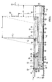
- FIG. 1 shows a ramp (1) in which a dock leveler can be installed.
- the space (38) under the dock leveler (39) is open.
- the tail lifts that may be attached to the vehicles are pushed into this room.
- a housing (3) which is preferably rectangular or trapezoidal and made, for example, of steel or plastic, is anchored in the floor (2) with fastenings (24) on the ramp floor (2).
- the hook (4) holds an underride guard (37), which is located in area (a) at height (h) from the floor of the ramp in front of the ramp.
- the underrun protection can be no less than the distance (b) from the ramp, since the distance (b) depends on the thickness of the crash bumpers (40) and the minimum width of the underride guard (37) are calculated and the length of the rear cover plate (15) corresponds to the device according to the invention.
- the housing (3) is of low construction, since its height (y) is decisive for whether tail lifts can still be pushed over the housing (3) of the holding structure into the existing tail gate opening (38).
- the maximum height (y) is preferably about 200 mm.
- a bevel (41) can be attached in front of the housing (3) to protect it, which prevents damage when docking with the tail lifts lowered.
- the system can also be equipped with an optical lighting system, such as a red-green traffic light outside the cargo area and a red-orange-green traffic light inside the cargo area.
- an optical lighting system such as a red-green traffic light outside the cargo area and a red-orange-green traffic light inside the cargo area.
- the hook drive and the traffic lights are controlled from a control box. Operation is carried out by operating switches and buttons.
- the switches can preferably be limit switches or proximity switches.
- the entire loading process then proceeds as follows:
- the hook (4) is in the horizontal rest position in the housing (3), the traffic light in the hall is red so that it cannot be loaded.
- the traffic light outside shows green, the arriving vehicle can drive backwards onto the ramp (1).
- the ramp staff actuates the hook (4) using appropriate electrical means, the traffic light on the outside switching to red, while the traffic light in the cargo area also lights up red.
- the hook (4) now turns to the vertical position and is automatically pushed towards the ramp against the underrun protection (37). As soon as this is reached, the vehicle is locked. It can no longer roll away or drive away.
- the traffic light inside now shows green, the charging process can begin, the traffic light outside remains red.
- the hook (4) is automatically unlocked again by the ramp personnel by actuating the appropriate electrical means.
- the traffic light jumps to red on the inside, and remains red on the outside until the hook (4) is in the horizontal rest position again. Then the traffic light on the outside changes to green again, the vehicle can now leave the ramp (1) again.
- the traffic light is red inside and green outside.
- the vehicle can drive up to the ramp (1).
- the ramp staff actuates the hook (4) that is still in retirement at the push of a button, the traffic light on the outside jumps to red, and the inside it stays on red.
- the hook (4) reaches the vertical position and then moves the entire area (a) towards the ramp in this position.
- the traffic light in the hall switches to an orange flashing light.
- the ramp personnel know that the vehicle is now not secured.
- a bypass is consciously operated manually, which moves the hook (4) back into the rest position. If the hook (4) is now in the rest position, the traffic light on the inside switches to orange continuous light and the traffic light remains red. Now an "unsecured charging process" can take place.
- the starting position of the traffic lights red inside and green outside
- the vehicle can then leave the ramp again.
- control box for control preferably has three basic operating switches, namely “locking”, unlocking ”and“ bypass for unsecured charging. ”All further switching and movements then take place automatically.
- the dock leveler (39) can only be used when the hook (4) holds the vehicle and can only be released when the dock leveler (39) is in the rest position again.
- FIGS. 2-4 The mechanism of the holding device according to the invention is shown in FIGS. 2-4 and is explained below:
- the hook (4) of the device according to the invention is in the starting or rest position horizontally in the housing (3) and adjoins the front cover plate (13) of the housing (3).
- the vehicle drives backwards on ramp (1).
- the underrun protection (37), or other fastening means, of the vehicle is located at height (h) in area (a) in front of the ramp (1).
- the hook (4) is mounted with the axis (5) between the upper hook guide (20) and the lower hook guide (21).
- the axis (5) is also rotatably supported in a tube (6) on which a rack (7) with a locking device is fastened in the direction of the front cover plate (13).
- the tube (6) is connected to a pull cable (8) which runs over deflection rollers (17) to the edge of the housing and then in the direction of the front cover plate (13) via a tensioning element (18) and is fixed in the abutment (19) of the housing (3).
- the tensioning element (18) is preferably a spring with a linear force distribution.
- the locking device of the rack (7) consists of three parts.
- Part 1 consists of an arm (33) and an approximately vertically arranged bolt (35), both of which are firmly connected and can rotate about the axis (32).
- Part 2 is an arm (31) which is vertically connected on the one hand to the arm (33) via axis (43), this connection having a margin. This margin is preferably an elongated hole.
- the arm (31) is connected via axis (42) to the rotatable arm (28), preferably via a round hole.
- Arm (28) is part of the third part of the locking device.
- This third part represents the operating arm of the entire mechanism and consists of an arm (28) which can be rotated about the axis (27) and which is connected at its lower end to the abutment (30) of the housing (3) via a spring element (29) .
- Part 1 bolt (35)
- Part 2 arm (31)
- the locking element can preferably have a spring element (34) to support the bolt (35), the spring force of which, however, must be so small that it does not influence the action of the operating arm (28) with the spring element (29).
- the device according to the invention also has a drive device (16) for the hook (4) located under the hook (4), which is connected to the corresponding fastening (9).
- the fastening (9) is in turn connected to the front support plate (11) via the guide rod (10) and furthermore has a lower and an upper guide (25, 26). In the rest position there is a second support plate (12) on the guide (23) above the support plate (11). Support plates (11) and (12) continue to have a lower support plate guide (22).
- the guide rod (10) also has a driver, not shown here, for the support plate (12).
- the drive or cylinder (16) is now activated for pushing out via known electrical / electronic means and pushes the attachment (9) onto the arm (28) (cf. FIG. 3).
- the front support plate (11) is pulled away from the ramp (1) via the guide rod (10).
- the driver (not shown) also pulls the support plate (12) as soon as the support plate (11) is on the guide (23).
- Support plate (11) presses against the hook (4).
- the resulting torque turns the hook (4) into the vertical position.
- the front cover plate (13) supports the upward movement of the hook (4), since the underside of the hook (4) slides over the cover plate (13).
- the support plate (11) thus pushes the hook (4) forward and at the same time slowly rotates it vertically.
- the pull cable (8) tensions the tensioning element (18) slowly and pulls it in the direction of the ramp (1). Finally, the axis (5) of the hook (4) abuts the abutment (36) and the support plate (11) turns the hook (4) in the vertical position.
- the drive or cylinder (16) reaches its maximum position.
- the attachment (9) then presses the operating arm (28) towards the front cover plate (14), the tension element (29) tensions, arm (31) pulls arm (33), possibly supported by a spring (34), also in the direction the front cover plate (14) and the bolt (35) then engage in the rack (7) (see FIG. 4).
- the tensioning element (18) now pulls the hook (4) in the (x) direction via the pull cable (8) until the hook (4) underrun protection of the vehicle hits, max. So over the area (a).
- the hook (4) is now in the holding position. If the vehicle tries to drive away, the underride guard presses against the hook (4) at height (h). Since the support plates (11) and (12) fill the entire guide area between positions (21) and (22), the hook (4) can no longer be turned back into the horizontal position in the entire work area (a).
- the bolt (35) prevents the rack (7) from being moved away from the ramp (1). The vehicle is therefore safely held in front of the ramp (1), and loading can now take place.
- arm (31) In order to ensure trouble-free functioning even when the vehicle presses the hook (4) away from the ramp (1), arm (31) has a clearance, preferably an elongated hole, at point (43). If the rack (7) presses against the bolt (35) with great force, the arm (33) tends to turn in the direction of the ramp (1). If there were a connection (43) without clearance, the voltages would also be transmitted to the drive (16) via arm (31) and (28).
- Unlocking after the positioning process is completed is as follows:
- the drive or cylinder (16) retracts in the direction of the ramp (1), the fastening (9) releases the arm (28) again, the spring element (29) pulls the arm (28) and, via the arm (31), also the arm (33) in the direction of the ramp (1), the latch (35) lifts out of the rack (7).
- the fastening (9) pushes the support plate (11) over the guide (23) in the direction of the ramp (1) via the guide rod (10).
- the support plate (11) first pushes the support plate (12) towards the ramp (1) until it comes to rest on the guide (23) in the rest position and then pushes over the support plate (12) also in the rest position.
- the device according to the invention can also be installed lowered into the floor (2) in front of the ramp (1) and instead of the underrun protection (37) e.g. block the wheels of the vehicle.
- This is possible by adapting the drive (16), which can then preferably be a chain drive or the like.
- the hook (4) can be made of a mechanically resistant material such as Plastic or a steel beam.
- the advantage of the device according to the invention lies in the fact that vehicles with tail lifts can also be locked, and optimum safety through special designs with regard to the chronological sequence of the charging process. Furthermore, no complicated, expensive construction measures are required for this.
- the device can be used to hold onto underrun protection or similar fastening means on vehicles or can also be used to lock wheels if no other fastening means are available.
Landscapes
- Engineering & Computer Science (AREA)
- Mechanical Engineering (AREA)
- Auxiliary Methods And Devices For Loading And Unloading (AREA)
- Motorcycle And Bicycle Frame (AREA)
- Control Of The Air-Fuel Ratio Of Carburetors (AREA)
- Non-Silver Salt Photosensitive Materials And Non-Silver Salt Photography (AREA)
- Steering Control In Accordance With Driving Conditions (AREA)
- Lock And Its Accessories (AREA)
Priority Applications (5)
| Application Number | Priority Date | Filing Date | Title |
|---|---|---|---|
| EP90107193A EP0452519B1 (fr) | 1990-04-14 | 1990-04-14 | Dispositif pour retenir une voiture à une rampe |
| DK90107193.6T DK0452519T3 (da) | 1990-04-14 | 1990-04-14 | Indretning til fastholdelse af et køretøj ved en rampe |
| ES90107193T ES2045621T3 (es) | 1990-04-14 | 1990-04-14 | Dispositivo para la sujecion de un vehiculo en una rampa. |
| AT90107193T ATE95794T1 (de) | 1990-04-14 | 1990-04-14 | Vorrichtung zum festhalten eines fahrzeuges an einer rampe. |
| DE90107193T DE59003090D1 (de) | 1990-04-14 | 1990-04-14 | Vorrichtung zum Festhalten eines Fahrzeuges an einer Rampe. |
Applications Claiming Priority (1)
| Application Number | Priority Date | Filing Date | Title |
|---|---|---|---|
| EP90107193A EP0452519B1 (fr) | 1990-04-14 | 1990-04-14 | Dispositif pour retenir une voiture à une rampe |
Publications (2)
| Publication Number | Publication Date |
|---|---|
| EP0452519A1 true EP0452519A1 (fr) | 1991-10-23 |
| EP0452519B1 EP0452519B1 (fr) | 1993-10-13 |
Family
ID=8203885
Family Applications (1)
| Application Number | Title | Priority Date | Filing Date |
|---|---|---|---|
| EP90107193A Expired - Lifetime EP0452519B1 (fr) | 1990-04-14 | 1990-04-14 | Dispositif pour retenir une voiture à une rampe |
Country Status (5)
| Country | Link |
|---|---|
| EP (1) | EP0452519B1 (fr) |
| AT (1) | ATE95794T1 (fr) |
| DE (1) | DE59003090D1 (fr) |
| DK (1) | DK0452519T3 (fr) |
| ES (1) | ES2045621T3 (fr) |
Cited By (9)
| Publication number | Priority date | Publication date | Assignee | Title |
|---|---|---|---|---|
| WO2004078618A1 (fr) * | 2003-01-10 | 2004-09-16 | Bengt-Olov Eriksson | Dispositif de calage |
| CN102700886A (zh) * | 2012-05-18 | 2012-10-03 | 张家港化工机械股份有限公司 | 伸缩式u型管用运输平台 |
| US8869948B2 (en) | 2009-12-01 | 2014-10-28 | 4Front Engineered Solutions, Inc. | Wheel chocks and associated methods and systems |
| WO2017067723A1 (fr) | 2015-10-21 | 2017-04-27 | CATAC CAPITAL GmbH | Dispositif de sécurisation de rampe de chargement |
| US9751702B1 (en) | 2016-06-06 | 2017-09-05 | ASSA ABLOY Entrance Systems, Inc. | Wheel chock systems |
| US10329104B2 (en) | 2016-04-04 | 2019-06-25 | Assa Abloy Entrance Systems Ab | Vehicle restraint |
| CN110441075A (zh) * | 2019-09-10 | 2019-11-12 | 邢台职业技术学院 | 具有制动功能的辊筒组测试架 |
| US10988329B2 (en) | 2019-02-15 | 2021-04-27 | Assa Abloy Entrance Systems Ab | Vehicle restraint |
| US11618642B2 (en) | 2020-08-20 | 2023-04-04 | Assa Abloy Entrance Systems Ab | Vehicle restraint systems and methods |
Families Citing this family (2)
| Publication number | Priority date | Publication date | Assignee | Title |
|---|---|---|---|---|
| GB2307464B (en) * | 1995-11-27 | 1998-01-14 | Fortress Doors Ltd | Vehicle restaint |
| DE29912260U1 (de) | 1999-07-14 | 1999-09-30 | Wijk Nederland | Festhaltevorrichtung für Räder eines Fahrzeugs |
Citations (3)
| Publication number | Priority date | Publication date | Assignee | Title |
|---|---|---|---|---|
| WO1988008403A1 (fr) * | 1987-04-22 | 1988-11-03 | Anthony Michael Harris | Systeme de positionnement pour vehicules commerciaux |
| US4818170A (en) * | 1987-02-24 | 1989-04-04 | Nova Technologies, Inc | Driveway truck restraining apparatus |
| EP0356073A2 (fr) * | 1988-08-16 | 1990-02-28 | Serco Corporation | Dispositif de retenue pour véhicules |
-
1990
- 1990-04-14 DE DE90107193T patent/DE59003090D1/de not_active Expired - Fee Related
- 1990-04-14 EP EP90107193A patent/EP0452519B1/fr not_active Expired - Lifetime
- 1990-04-14 DK DK90107193.6T patent/DK0452519T3/da active
- 1990-04-14 AT AT90107193T patent/ATE95794T1/de not_active IP Right Cessation
- 1990-04-14 ES ES90107193T patent/ES2045621T3/es not_active Expired - Lifetime
Patent Citations (3)
| Publication number | Priority date | Publication date | Assignee | Title |
|---|---|---|---|---|
| US4818170A (en) * | 1987-02-24 | 1989-04-04 | Nova Technologies, Inc | Driveway truck restraining apparatus |
| WO1988008403A1 (fr) * | 1987-04-22 | 1988-11-03 | Anthony Michael Harris | Systeme de positionnement pour vehicules commerciaux |
| EP0356073A2 (fr) * | 1988-08-16 | 1990-02-28 | Serco Corporation | Dispositif de retenue pour véhicules |
Cited By (14)
| Publication number | Priority date | Publication date | Assignee | Title |
|---|---|---|---|---|
| WO2004078618A1 (fr) * | 2003-01-10 | 2004-09-16 | Bengt-Olov Eriksson | Dispositif de calage |
| US7537095B2 (en) | 2003-01-10 | 2009-05-26 | Bengt-Olov Eriksson | Chocking apparatus |
| US8869948B2 (en) | 2009-12-01 | 2014-10-28 | 4Front Engineered Solutions, Inc. | Wheel chocks and associated methods and systems |
| CN102700886A (zh) * | 2012-05-18 | 2012-10-03 | 张家港化工机械股份有限公司 | 伸缩式u型管用运输平台 |
| CN102700886B (zh) * | 2012-05-18 | 2014-04-09 | 张家港化工机械股份有限公司 | 伸缩式u型管用运输平台 |
| DE102015117957A1 (de) | 2015-10-21 | 2017-04-27 | CATAC CAPITAL GmbH | Laderampensicherungseinrichtung |
| WO2017067723A1 (fr) | 2015-10-21 | 2017-04-27 | CATAC CAPITAL GmbH | Dispositif de sécurisation de rampe de chargement |
| DE102015117957B4 (de) | 2015-10-21 | 2020-07-09 | CATAC CAPITAL GmbH | Laderampensicherungseinrichtung |
| US10329104B2 (en) | 2016-04-04 | 2019-06-25 | Assa Abloy Entrance Systems Ab | Vehicle restraint |
| US9751702B1 (en) | 2016-06-06 | 2017-09-05 | ASSA ABLOY Entrance Systems, Inc. | Wheel chock systems |
| US10329105B2 (en) | 2016-06-06 | 2019-06-25 | Assa Abloy Entrance Systems Ab | Wheel chock systems |
| US10988329B2 (en) | 2019-02-15 | 2021-04-27 | Assa Abloy Entrance Systems Ab | Vehicle restraint |
| CN110441075A (zh) * | 2019-09-10 | 2019-11-12 | 邢台职业技术学院 | 具有制动功能的辊筒组测试架 |
| US11618642B2 (en) | 2020-08-20 | 2023-04-04 | Assa Abloy Entrance Systems Ab | Vehicle restraint systems and methods |
Also Published As
| Publication number | Publication date |
|---|---|
| EP0452519B1 (fr) | 1993-10-13 |
| DK0452519T3 (da) | 1993-11-22 |
| ES2045621T3 (es) | 1994-01-16 |
| ATE95794T1 (de) | 1993-10-15 |
| DE59003090D1 (de) | 1993-11-18 |
Similar Documents
| Publication | Publication Date | Title |
|---|---|---|
| EP2380833B1 (fr) | Déflecteur de pneu pour le guidage d'un camion | |
| EP0416539B1 (fr) | Dispositif d'accès pour véhicules automobiles, en particulier pour autobus | |
| EP0589158A1 (fr) | Serrure commandable à distance, en particulier pour des portières de véhicule automobile | |
| EP3549900B1 (fr) | Élévateur pour véhicules automobiles | |
| EP0452519B1 (fr) | Dispositif pour retenir une voiture à une rampe | |
| DE4301627A1 (de) | Schüttgutplaniervorrichtung | |
| DE2242691A1 (de) | Unterirdisches automatisches parksystem fuer fahrzeuge | |
| DE2318774A1 (de) | Antrieb fuer eine fahrzeugtuer | |
| EP0235492A1 (fr) | Bloc-tiroir avec un volet obturateur pour un dispositif sectionneur | |
| DE4327084C2 (de) | Vorrichtung für das automatische Öffnen und Schließen einer Gleittür | |
| DE4125448C2 (de) | Elektromotorischer Stellantrieb für eine zentrale Türverriegelungsanlage eines Kraftfahrzeugs | |
| EP0678639B1 (fr) | Dispositif de verrouillage pour volets, portes et éléments similaires mobiles sur un rail fixe | |
| DE3127019A1 (de) | "vorrichtung fuer einen submast-hublader mit in fahrzeugrichtung laengsbeweglich gehaltenem batteriewagen" | |
| EP1748009B1 (fr) | Dispositif de blocage pour véhicule utilitaire | |
| DE2849194A1 (de) | Teleskoptransportbehaelter | |
| EP1057696A2 (fr) | Dispositif à arceau de sécurité pour véhicules | |
| DE2221575A1 (de) | Eisenbahnwagen zur personenbefoerderung mit trittstufen | |
| DE4311287C2 (de) | Sicherheitsentriegelung für über Kopf bewegbare Torblätter | |
| EP0781892B1 (fr) | Porte coulissante automatique avec au moins un vantail | |
| EP0158735A1 (fr) | Appareil de levage et de garage pour avions | |
| DE19622290C1 (de) | Elektromechanischer Antrieb für eine Schiebetür | |
| EP0698545A1 (fr) | Chariot à deux étages | |
| DE19638741C2 (de) | Elektromechanischer Antrieb für eine Schiebetür | |
| EP0548633B1 (fr) | Dispositif pour retenir un véhicule à une rampe | |
| DE2132189C3 (fr) |
Legal Events
| Date | Code | Title | Description |
|---|---|---|---|
| PUAI | Public reference made under article 153(3) epc to a published international application that has entered the european phase |
Free format text: ORIGINAL CODE: 0009012 |
|
| AK | Designated contracting states |
Kind code of ref document: A1 Designated state(s): AT BE CH DE DK ES FR GB GR IT LI LU NL SE |
|
| 17P | Request for examination filed |
Effective date: 19911114 |
|
| 17Q | First examination report despatched |
Effective date: 19920907 |
|
| GRAA | (expected) grant |
Free format text: ORIGINAL CODE: 0009210 |
|
| AK | Designated contracting states |
Kind code of ref document: B1 Designated state(s): AT BE CH DE DK ES FR GB GR IT LI LU NL SE |
|
| REF | Corresponds to: |
Ref document number: 95794 Country of ref document: AT Date of ref document: 19931015 Kind code of ref document: T |
|
| REF | Corresponds to: |
Ref document number: 59003090 Country of ref document: DE Date of ref document: 19931118 |
|
| REG | Reference to a national code |
Ref country code: DK Ref legal event code: T3 |
|
| ITF | It: translation for a ep patent filed |
Owner name: ING. A. GIAMBROCONO & C |
|
| GBT | Gb: translation of ep patent filed (gb section 77(6)(a)/1977) |
Effective date: 19931108 |
|
| REG | Reference to a national code |
Ref country code: ES Ref legal event code: FG2A Ref document number: 2045621 Country of ref document: ES Kind code of ref document: T3 |
|
| ET | Fr: translation filed | ||
| REG | Reference to a national code |
Ref country code: GR Ref legal event code: FG4A Free format text: 3010224 |
|
| EPTA | Lu: last paid annual fee | ||
| PLBE | No opposition filed within time limit |
Free format text: ORIGINAL CODE: 0009261 |
|
| STAA | Information on the status of an ep patent application or granted ep patent |
Free format text: STATUS: NO OPPOSITION FILED WITHIN TIME LIMIT |
|
| 26N | No opposition filed | ||
| EAL | Se: european patent in force in sweden |
Ref document number: 90107193.6 |
|
| PGFP | Annual fee paid to national office [announced via postgrant information from national office to epo] |
Ref country code: LU Payment date: 20000218 Year of fee payment: 11 |
|
| PGFP | Annual fee paid to national office [announced via postgrant information from national office to epo] |
Ref country code: SE Payment date: 20000310 Year of fee payment: 11 |
|
| PGFP | Annual fee paid to national office [announced via postgrant information from national office to epo] |
Ref country code: DK Payment date: 20000405 Year of fee payment: 11 |
|
| PGFP | Annual fee paid to national office [announced via postgrant information from national office to epo] |
Ref country code: GR Payment date: 20000427 Year of fee payment: 11 |
|
| PG25 | Lapsed in a contracting state [announced via postgrant information from national office to epo] |
Ref country code: LU Free format text: LAPSE BECAUSE OF NON-PAYMENT OF DUE FEES Effective date: 20010414 Ref country code: DK Free format text: LAPSE BECAUSE OF NON-PAYMENT OF DUE FEES Effective date: 20010414 |
|
| PG25 | Lapsed in a contracting state [announced via postgrant information from national office to epo] |
Ref country code: SE Free format text: LAPSE BECAUSE OF NON-PAYMENT OF DUE FEES Effective date: 20010415 |
|
| PG25 | Lapsed in a contracting state [announced via postgrant information from national office to epo] |
Ref country code: GR Free format text: LAPSE BECAUSE OF NON-PAYMENT OF DUE FEES Effective date: 20010430 |
|
| EUG | Se: european patent has lapsed |
Ref document number: 90107193.6 |
|
| REG | Reference to a national code |
Ref country code: GB Ref legal event code: IF02 |
|
| PGFP | Annual fee paid to national office [announced via postgrant information from national office to epo] |
Ref country code: ES Payment date: 20020311 Year of fee payment: 13 |
|
| PGFP | Annual fee paid to national office [announced via postgrant information from national office to epo] |
Ref country code: CH Payment date: 20020415 Year of fee payment: 13 |
|
| PGFP | Annual fee paid to national office [announced via postgrant information from national office to epo] |
Ref country code: AT Payment date: 20020422 Year of fee payment: 13 |
|
| PGFP | Annual fee paid to national office [announced via postgrant information from national office to epo] |
Ref country code: GB Payment date: 20030324 Year of fee payment: 14 |
|
| PG25 | Lapsed in a contracting state [announced via postgrant information from national office to epo] |
Ref country code: AT Free format text: LAPSE BECAUSE OF NON-PAYMENT OF DUE FEES Effective date: 20030414 |
|
| PG25 | Lapsed in a contracting state [announced via postgrant information from national office to epo] |
Ref country code: ES Free format text: LAPSE BECAUSE OF NON-PAYMENT OF DUE FEES Effective date: 20030415 |
|
| PGFP | Annual fee paid to national office [announced via postgrant information from national office to epo] |
Ref country code: NL Payment date: 20030416 Year of fee payment: 14 |
|
| PGFP | Annual fee paid to national office [announced via postgrant information from national office to epo] |
Ref country code: FR Payment date: 20030417 Year of fee payment: 14 |
|
| PGFP | Annual fee paid to national office [announced via postgrant information from national office to epo] |
Ref country code: BE Payment date: 20030425 Year of fee payment: 14 |
|
| PGFP | Annual fee paid to national office [announced via postgrant information from national office to epo] |
Ref country code: DE Payment date: 20030428 Year of fee payment: 14 |
|
| PG25 | Lapsed in a contracting state [announced via postgrant information from national office to epo] |
Ref country code: LI Free format text: LAPSE BECAUSE OF NON-PAYMENT OF DUE FEES Effective date: 20030430 Ref country code: CH Free format text: LAPSE BECAUSE OF NON-PAYMENT OF DUE FEES Effective date: 20030430 |
|
| REG | Reference to a national code |
Ref country code: CH Ref legal event code: PL |
|
| PG25 | Lapsed in a contracting state [announced via postgrant information from national office to epo] |
Ref country code: GB Free format text: LAPSE BECAUSE OF NON-PAYMENT OF DUE FEES Effective date: 20040414 |
|
| PG25 | Lapsed in a contracting state [announced via postgrant information from national office to epo] |
Ref country code: BE Free format text: LAPSE BECAUSE OF NON-PAYMENT OF DUE FEES Effective date: 20040430 |
|
| REG | Reference to a national code |
Ref country code: ES Ref legal event code: FD2A Effective date: 20030415 |
|
| BERE | Be: lapsed |
Owner name: *VAN WIJK NEDERLAND B.V. Effective date: 20040430 |
|
| PG25 | Lapsed in a contracting state [announced via postgrant information from national office to epo] |
Ref country code: NL Free format text: LAPSE BECAUSE OF NON-PAYMENT OF DUE FEES Effective date: 20041101 |
|
| PG25 | Lapsed in a contracting state [announced via postgrant information from national office to epo] |
Ref country code: DE Free format text: LAPSE BECAUSE OF NON-PAYMENT OF DUE FEES Effective date: 20041103 |
|
| GBPC | Gb: european patent ceased through non-payment of renewal fee |
Effective date: 20040414 |
|
| PG25 | Lapsed in a contracting state [announced via postgrant information from national office to epo] |
Ref country code: FR Free format text: LAPSE BECAUSE OF NON-PAYMENT OF DUE FEES Effective date: 20041231 |
|
| NLV4 | Nl: lapsed or anulled due to non-payment of the annual fee |
Effective date: 20041101 |
|
| REG | Reference to a national code |
Ref country code: FR Ref legal event code: ST |
|
| PG25 | Lapsed in a contracting state [announced via postgrant information from national office to epo] |
Ref country code: IT Free format text: LAPSE BECAUSE OF NON-PAYMENT OF DUE FEES;WARNING: LAPSES OF ITALIAN PATENTS WITH EFFECTIVE DATE BEFORE 2007 MAY HAVE OCCURRED AT ANY TIME BEFORE 2007. THE CORRECT EFFECTIVE DATE MAY BE DIFFERENT FROM THE ONE RECORDED. Effective date: 20050414 |