EP0452379B1 - Bruleur lineaire a gaz ayant une largeur reglable - Google Patents
Bruleur lineaire a gaz ayant une largeur reglable Download PDFInfo
- Publication number
- EP0452379B1 EP0452379B1 EP90901598A EP90901598A EP0452379B1 EP 0452379 B1 EP0452379 B1 EP 0452379B1 EP 90901598 A EP90901598 A EP 90901598A EP 90901598 A EP90901598 A EP 90901598A EP 0452379 B1 EP0452379 B1 EP 0452379B1
- Authority
- EP
- European Patent Office
- Prior art keywords
- gas
- tube
- air
- injectors
- burner
- Prior art date
- Legal status (The legal status is an assumption and is not a legal conclusion. Google has not performed a legal analysis and makes no representation as to the accuracy of the status listed.)
- Expired - Lifetime
Links
- 230000008878 coupling Effects 0.000 claims description 5
- 238000010168 coupling process Methods 0.000 claims description 5
- 238000005859 coupling reaction Methods 0.000 claims description 5
- 230000000903 blocking effect Effects 0.000 claims 8
- 238000007789 sealing Methods 0.000 abstract description 5
- 239000007789 gas Substances 0.000 description 58
- 239000004744 fabric Substances 0.000 description 7
- 238000002485 combustion reaction Methods 0.000 description 6
- 238000001035 drying Methods 0.000 description 5
- 125000006850 spacer group Chemical group 0.000 description 4
- 238000010438 heat treatment Methods 0.000 description 3
- 229910000831 Steel Inorganic materials 0.000 description 2
- 238000009998 heat setting Methods 0.000 description 2
- 238000009434 installation Methods 0.000 description 2
- VNWKTOKETHGBQD-UHFFFAOYSA-N methane Chemical compound C VNWKTOKETHGBQD-UHFFFAOYSA-N 0.000 description 2
- 239000010959 steel Substances 0.000 description 2
- 229910000906 Bronze Inorganic materials 0.000 description 1
- 241001080024 Telles Species 0.000 description 1
- 239000010974 bronze Substances 0.000 description 1
- 238000010276 construction Methods 0.000 description 1
- KUNSUQLRTQLHQQ-UHFFFAOYSA-N copper tin Chemical compound [Cu].[Sn] KUNSUQLRTQLHQQ-UHFFFAOYSA-N 0.000 description 1
- 238000001514 detection method Methods 0.000 description 1
- 230000001627 detrimental effect Effects 0.000 description 1
- 239000000975 dye Substances 0.000 description 1
- 238000005485 electric heating Methods 0.000 description 1
- 230000005611 electricity Effects 0.000 description 1
- 238000005516 engineering process Methods 0.000 description 1
- 210000004907 gland Anatomy 0.000 description 1
- 239000003915 liquefied petroleum gas Substances 0.000 description 1
- 238000004519 manufacturing process Methods 0.000 description 1
- 239000002184 metal Substances 0.000 description 1
- 239000000203 mixture Substances 0.000 description 1
- 239000003345 natural gas Substances 0.000 description 1
- 230000005855 radiation Effects 0.000 description 1
- 230000000717 retained effect Effects 0.000 description 1
- 239000004753 textile Substances 0.000 description 1
- 238000009988 textile finishing Methods 0.000 description 1
- 238000011282 treatment Methods 0.000 description 1
Images

Classifications
-
- F—MECHANICAL ENGINEERING; LIGHTING; HEATING; WEAPONS; BLASTING
- F26—DRYING
- F26B—DRYING SOLID MATERIALS OR OBJECTS BY REMOVING LIQUID THEREFROM
- F26B13/00—Machines and apparatus for drying fabrics, fibres, yarns, or other materials in long lengths, with progressive movement
- F26B13/10—Arrangements for feeding, heating or supporting materials; Controlling movement, tension or position of materials
- F26B13/22—Arrangements of gas flames
-
- F—MECHANICAL ENGINEERING; LIGHTING; HEATING; WEAPONS; BLASTING
- F23—COMBUSTION APPARATUS; COMBUSTION PROCESSES
- F23D—BURNERS
- F23D14/00—Burners for combustion of a gas, e.g. of a gas stored under pressure as a liquid
- F23D14/20—Non-premix gas burners, i.e. in which gaseous fuel is mixed with combustion air on arrival at the combustion zone
- F23D14/22—Non-premix gas burners, i.e. in which gaseous fuel is mixed with combustion air on arrival at the combustion zone with separate air and gas feed ducts, e.g. with ducts running parallel or crossing each other
-
- F—MECHANICAL ENGINEERING; LIGHTING; HEATING; WEAPONS; BLASTING
- F26—DRYING
- F26B—DRYING SOLID MATERIALS OR OBJECTS BY REMOVING LIQUID THEREFROM
- F26B13/00—Machines and apparatus for drying fabrics, fibres, yarns, or other materials in long lengths, with progressive movement
- F26B13/10—Arrangements for feeding, heating or supporting materials; Controlling movement, tension or position of materials
- F26B13/14—Rollers, drums, cylinders; Arrangement of drives, supports, bearings, cleaning
- F26B13/18—Rollers, drums, cylinders; Arrangement of drives, supports, bearings, cleaning heated or cooled, e.g. from inside, the material being dried on the outside surface by conduction
- F26B13/183—Arrangements for heating, cooling, condensate removal
- F26B13/186—Arrangements for heating, cooling, condensate removal using combustion
Definitions
- the present invention relates to a linear gas and blown air burner, comprising an air distributor tube connected to a pressurized air supply, a gas distributor tube mounted inside the air distributor tube and provided with a gas inlet connected to a pressurized gas supply, and at least one longitudinal row of gas injectors, these injectors extending substantially radially from the gas distributor tube through air injectors mounted on orifices air outlet formed in the wall of the air distributor tube, each gas injector being mounted on a gas outlet orifice formed in the wall of the gas distributor tube.
- Such a linear gas burner described in European patent N ° 0190091, has great advantages from the point of view of safety, since the mixing of the gas with the blown air takes place only at the entrance to the combustion zone. , and from the point of view of operating convenience since it has a very high ratio between its maximum power and its minimum power. This is why it is very widely used, especially in the food industry and in the textile industry. This is the case in particular in textile finishing machines, especially the drying and heat setting reams, where it allows both an optimal distribution of heat over the entire surface of the product to be treated and a power modulation which will up to 1:50 and which allows, in applications as different as drying fabrics or heat setting dyes, work at very precise temperatures whatever the heat requirement.
- the present invention therefore aims to provide a linear gas burner of the type indicated in the preamble, equipped with a device for precisely adjusting the active width of the flame, keeping it engaged or not, in a way individual, at least the injectors located near one end of the row.
- the burner according to the invention comprises a gas distributor tube closed internally by at least one sliding shutter member arranged to block the supply of gas to a section of this tube comprising one or more gas injectors, said shutter member being coupled to a control bar disposed longitudinally in this tube and connected to control means located outside this tube, and all the air injectors of said row continue to be supplied with air when the gas supply to one or more gas injectors is blocked by said shutter member.
- control bar is rotatable about its axis and comprises at least one threaded section which is engaged in a corresponding threaded bore of the shutter member, and the shutter member is provided with means preventing it from rotating in the gas distributor tube.
- the control bar can be rotatably mounted in two elements closing the ends of the gas distributor tube, the bar passing through at least one of the elements to be connected to the control means.
- the gas distributor tube has a circular cross section, as does the closure member, and to prevent the closure member from rotating in the tube, the bar control and the threaded bore of this member are arranged along an axis which is offset from the axis of the tube.
- the gas distributor tube is equipped with two sliding shutter members and a lateral gas inlet located between these two members.
- the control bar comprises two elements threaded in opposite directions and engaged respectively in the two shutter members, so as to slide these two members simultaneously in opposite directions.
- the control bar can be connected to the control means by means of a removable coupling.
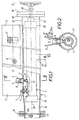
- the linear burner shown comprises an external air distributor tube 1, a gas distributor tube 2 mounted inside the tube 1 in an adjustable position by means of a pair of threaded rods 3 screwed into the wall of the tube 2 and provided with locking nuts 4, and a row of gas injectors 5 fixed to the tube 2 perpendicular thereto and extending outwards, each through an air injector 6 formed by a tubular opening fixed in an orifice 7 of the tube 1.
- Each air injector contains a swirl ring 8, favoring the mixing of the gas and the combustion air at the outlet of the gas injector 5.
- This type of injector is fine known and it is described in more detail in EP-A-0 190 091.
- each gas injector 5 is provided with a threaded base 9 which is screwed into a threaded bore 10 of the gas distributor tube 2 .
- the injectors 5 and 6 are arranged in a row and all open into a combustion zone 11 defined by a flame guide 12 made of refractory steel, which is fixed externally to the tube 1 by bolting in slides (not shown), themselves same bolted to the tube 1.
- the flame guide 12 carries an electric igniter 16 and a flame control device 17, for example by detection of ultraviolet radiation.
- the arrangements mentioned above are well known in the field of gas and supply air burners.
- the gas distributor tube 2 is a straight cylindrical tube, having a longitudinal axis 20 disposed approximately, but not necessarily, in the center of the tube 1.
- the tube 2 is provided with '' a side gas inlet nozzle 21 connected to a supply pipe 22 which passes through the wall of the tube 1 and which supplies the burner with gas coming, as indicated by arrow G, from a control valve not shown .
- This valve allows to regulate the gas flow, therefore the power of the burner.
- the gas may for example be natural gas, liquefied petroleum gas or a manufactured gas such as town or blast furnace gas.
- One end 24 of the air distributor tube 1 is connected to an air supply pipe 25, by a flange assembly 26 equipped with a diaphragm 26a controlling the air flow, which is blown at low pressure and arrives as indicated by arrow A, then passes around the gas distributor tube 2 to reach the air injectors 6 which mix it with the gas at the entrance to the combustion zone 11.
- the other end 27 of the tube 1 is closed by a cover 28 fixed to a flange 29 of the tube and traversed by a control shaft 30 provided with a manual flywheel 31 or with an automatic control.
- the gas distributor tube 2 is shown in more detail in FIGS. 3 and 4. It is a straight cylindrical steel tube, supported by the threaded rods 3 and carrying the gas injectors 5. For simplicity, there is n 'has shown that five gas injectors 5a to 5e. Each end of the tube 2 is closed by a plate 32, 33 fixed by means of a threaded cap 34, 35 screwed externally to the tube 2.
- Two closure nuts 36, 37 are slidably mounted in the inner bore of the tube 2 and each of them closes this bore in a sealed manner between the corresponding end of the tube and the gas inlet nozzle 21.
- Each of these nuts can be formed for example by a cylindrical piece of bronze pierced with an eccentric longitudinal bore provided with a thread 38, 39 and centered on an axis 40 which is offset by a distance E with respect to l 'axis 20 of the tube 2 and the outer surface of the nut. In this example, this offset E is lateral, but it could be provided in another direction.
- a rotary bar 41 also centered on the axis 40, extends longitudinally in the tube 2 and is carried by gland bearings 42, 43 mounted in the plates 32 and 33.
- One end 44 of the bar 41 passes through the cap 35 and is connected to the control shaft 30 by means of a suitable coupling 45 (FIG. 1), for example a fork coupling.
- a suitable coupling 45 for example a fork coupling.
- the rotary bar 41 is subdivided into two symmetrical elements 48 and 49 which are made integral in rotation by a coupling sleeve 50 and elastic pins 51, approximately in the middle of the length of the tube 2.
- each element 48, 49 has a cylindrical section 52, 53 rotatably supported by a respective spacer 54, 55 fixed in the tube 2 by screws 56.
- the element 48, 49 is retained longitudinally by an elastic ring of the "circlip" type 57.
- each spacer 54, 55 is pierced with several holes 60, 61 for the passage of gas along the tube 2.
- the two nuts 36 and 37 cannot turn thanks to the fact that the bar 41 is held by its bearings in an eccentric position, and slides in the tube while approaching symmetrically one from the other, while they move away if the bar 41 is turned in the opposite.
- the nuts 36 and 37 will close the orifices 10 in which are mounted the two injectors 5a and 5e located at the end of the row.
- the linear flame of the burner will be symmetrically shortened by a small distance at its two ends, each time that the nuts 36, 37 block the supply of an additional pair of injectors 5.
- the flame will widen if the 'the handwheel 31 and the bar 41 are turned in the opposite direction.
- provision can be made to adjust the gas supply flow at the same time. This adjustment can be done automatically using a pressure sensor on the supply line 22. In another embodiment, it can be controlled by a motorized control of the flame width adjustment mechanism, actuating the rotary bar 41. During this time, the air continues to be supplied to the combustion zone 11 by all the injectors 6, even where the injectors 5 no longer receive gas. In a drying drum as mentioned above, this has the advantage of helping to cool the end regions of the drum.
- each nut 36, 37 is replaced by nuts 66, 67 having a threaded bore centered on the axis 20 of the tube 2
- each nut is provided with a lateral groove 68 which slides on a corresponding longitudinal key 69, fixed in the tube 2 by screws 70 and extending over the entire length of the stroke of the 'nut.
- This arrangement makes it possible to dispense with the spacers 54, 55 of the previous example and to use a bar 41 in one piece.
- the eccentric arrangement has the advantage of facilitating sealing and manufacturing.
- each nut 36, 37 or 66, 67 could also be designed in two elements, one of which provides sealing and the other serves as the nut proper on the thread of the bar 41.
- shutter members constituted by the nuts 36, 37 could be replaced by members controlled in a different manner, for example by means of sliding rods controlled from the outside of the burner by a linear actuator.
Landscapes
- Engineering & Computer Science (AREA)
- Mechanical Engineering (AREA)
- General Engineering & Computer Science (AREA)
- Chemical & Material Sciences (AREA)
- Combustion & Propulsion (AREA)
- Textile Engineering (AREA)
- Gas Burners (AREA)
- Pre-Mixing And Non-Premixing Gas Burner (AREA)
- Glass Melting And Manufacturing (AREA)
Applications Claiming Priority (3)
| Application Number | Priority Date | Filing Date | Title |
|---|---|---|---|
| FR8900240A FR2641601A1 (fr) | 1989-01-06 | 1989-01-06 | Bruleur lineaire a gaz ayant une largeur reglable |
| FR8900240 | 1989-01-06 | ||
| PCT/FR1990/000004 WO1990007680A1 (fr) | 1989-01-06 | 1990-01-04 | Bruleur lineaire a gaz ayant une largeur reglable |
Publications (2)
| Publication Number | Publication Date |
|---|---|
| EP0452379A1 EP0452379A1 (fr) | 1991-10-23 |
| EP0452379B1 true EP0452379B1 (fr) | 1994-12-07 |
Family
ID=9377602
Family Applications (1)
| Application Number | Title | Priority Date | Filing Date |
|---|---|---|---|
| EP90901598A Expired - Lifetime EP0452379B1 (fr) | 1989-01-06 | 1990-01-04 | Bruleur lineaire a gaz ayant une largeur reglable |
Country Status (8)
| Country | Link |
|---|---|
| US (1) | US5152685A (cg-RX-API-DMAC7.html) |
| EP (1) | EP0452379B1 (cg-RX-API-DMAC7.html) |
| JP (1) | JPH04502664A (cg-RX-API-DMAC7.html) |
| AT (1) | ATE115262T1 (cg-RX-API-DMAC7.html) |
| CA (1) | CA2045521A1 (cg-RX-API-DMAC7.html) |
| DE (1) | DE69014858T2 (cg-RX-API-DMAC7.html) |
| FR (1) | FR2641601A1 (cg-RX-API-DMAC7.html) |
| WO (1) | WO1990007680A1 (cg-RX-API-DMAC7.html) |
Families Citing this family (10)
| Publication number | Priority date | Publication date | Assignee | Title |
|---|---|---|---|---|
| FR2675242B1 (fr) * | 1991-04-15 | 1993-07-09 | Gaz De France | Bruleur lineaire. |
| NL9401723A (nl) * | 1994-10-18 | 1996-06-03 | Gastec Nv | Gasgestookte drooginrichting. |
| US5791065A (en) * | 1997-02-06 | 1998-08-11 | Asea Brown Boveri, Inc. | Gas heated paper dryer |
| ES2145681B1 (es) * | 1997-07-09 | 2001-04-01 | Gamero Llorca Jose | Cocina industrial. |
| US7975489B2 (en) * | 2003-09-05 | 2011-07-12 | Kawasaki Jukogyo Kabushiki Kaisha | Catalyst module overheating detection and methods of response |
| US8147240B2 (en) | 2009-03-17 | 2012-04-03 | Hni Technologies Inc. | Thin chamber burner |
| US10571117B1 (en) | 2015-08-04 | 2020-02-25 | Warming Trends, Llc | System and method for building ornamental flame displays |
| IT201800010597A1 (it) * | 2018-11-27 | 2020-05-27 | Andrea Battistin | Macchina per la produzione di carta di tipo tissue. |
| US12055300B2 (en) | 2020-11-24 | 2024-08-06 | Warming Trends, Llc | Flame burner |
| CN115289469A (zh) * | 2022-06-28 | 2022-11-04 | 大唐黑龙江发电有限公司哈尔滨第一热电厂 | 径向插入轴向点火型内燃燃烧器 |
Family Cites Families (7)
| Publication number | Priority date | Publication date | Assignee | Title |
|---|---|---|---|---|
| US1497954A (en) * | 1922-02-28 | 1924-06-17 | Joseph P Shaw | Low-pressure gas burner |
| GB204756A (en) * | 1922-06-30 | 1923-10-01 | Archie Ewing | Improvements in gas burners for fabric singeing and like machines |
| US1521493A (en) * | 1923-12-18 | 1924-12-30 | Whikehart John | Gas burner |
| US1656549A (en) * | 1927-03-19 | 1928-01-17 | Warmack George | Gas burner |
| US1820493A (en) * | 1929-08-22 | 1931-08-25 | Reagan Martin | Gas burner |
| FR2576087A1 (fr) * | 1985-01-15 | 1986-07-18 | Alsace Gaz Ind Sa | Bruleur lineaire a gaz et a air souffle |
| JPS6438512A (en) * | 1987-08-05 | 1989-02-08 | Rinnai Kk | Forced draft type combustion apparatus |
-
1989
- 1989-01-06 FR FR8900240A patent/FR2641601A1/fr active Granted
-
1990
- 1990-01-04 US US07/721,463 patent/US5152685A/en not_active Expired - Fee Related
- 1990-01-04 EP EP90901598A patent/EP0452379B1/fr not_active Expired - Lifetime
- 1990-01-04 WO PCT/FR1990/000004 patent/WO1990007680A1/fr not_active Ceased
- 1990-01-04 DE DE69014858T patent/DE69014858T2/de not_active Expired - Fee Related
- 1990-01-04 JP JP2501764A patent/JPH04502664A/ja active Pending
- 1990-01-04 AT AT90901598T patent/ATE115262T1/de not_active IP Right Cessation
- 1990-01-04 CA CA002045521A patent/CA2045521A1/fr not_active Abandoned
Also Published As
| Publication number | Publication date |
|---|---|
| CA2045521A1 (fr) | 1990-07-07 |
| US5152685A (en) | 1992-10-06 |
| ATE115262T1 (de) | 1994-12-15 |
| FR2641601A1 (fr) | 1990-07-13 |
| DE69014858T2 (de) | 1995-05-24 |
| JPH04502664A (ja) | 1992-05-14 |
| EP0452379A1 (fr) | 1991-10-23 |
| FR2641601B1 (cg-RX-API-DMAC7.html) | 1994-07-13 |
| DE69014858D1 (de) | 1995-01-19 |
| WO1990007680A1 (fr) | 1990-07-12 |
Similar Documents
| Publication | Publication Date | Title |
|---|---|---|
| EP0452379B1 (fr) | Bruleur lineaire a gaz ayant une largeur reglable | |
| FR2566087A1 (fr) | Robinet de permutation de flux pour le soufflage de fluides dans un creuset de metal fondu | |
| EP0010038A1 (fr) | Chalumeau à deux gaz | |
| FR2531177A1 (fr) | Vanne a obturateur spherique et a enveloppe chauffante | |
| FR2734621A1 (fr) | Dispositif d'actionnement combine de deux organes a commande rotative, et chalumeau le comportant | |
| FR2470317A1 (fr) | Vanne a disques de commande, utile notamment dans le domaine sanitaire | |
| EP0892113A1 (fr) | Machine pour la pose d'un revêtement thermosoudable en bande | |
| FR2837916A1 (fr) | Procede pour faire varier la position du point chaud d'une flamme | |
| EP0774620A1 (fr) | Brûleur à combustible liquide ou gazeux à très faible émission d'oxydes d'azote | |
| FR1464931A (fr) | Dispositif de commande du combustible pour appareil à brûleur principal et à brûleur-pilote | |
| FR3089590A1 (fr) | Cartouche thermostatique pour robinet mitigeur | |
| FR2683607A3 (fr) | Vanne de commande a dispositif magnetique de securite pour cuisinieres a gaz. | |
| EP0234991A1 (fr) | Régulateur d'alimentation pour brûleur à gaz et sa combinaison avec un brûleur | |
| EP0190091B1 (fr) | Brûleur linéaire à gaz et à air soufflé | |
| WO2020115195A1 (fr) | Cartouche thermostatique pour robinet mitigeur | |
| BE503720A (fr) | Perfectionnements a des vannes de melange controlees par un thermostat | |
| EP0080421A1 (fr) | Mitigeur d'eau | |
| FR2765953A1 (fr) | Bruleur pour dispositif de desherbage thermique | |
| WO1996018070A1 (fr) | Bruleur muni d'un dispositif de commande synchronise | |
| FR2623601A2 (fr) | Perfectionnements apportes aux systemes de securite totale a bi-metal pour chauffe-eau a gaz | |
| BE440484A (cg-RX-API-DMAC7.html) | ||
| BE506656A (cg-RX-API-DMAC7.html) | ||
| CA2288079A1 (fr) | Appareil de chauffage | |
| FR2641057A1 (en) | Combustion head for a gas burner, or combined gas-and-paraffin burner and burner equipped with such a head | |
| FR2722705A1 (fr) | Dispositif de melange air/gaz |
Legal Events
| Date | Code | Title | Description |
|---|---|---|---|
| PUAI | Public reference made under article 153(3) epc to a published international application that has entered the european phase |
Free format text: ORIGINAL CODE: 0009012 |
|
| 17P | Request for examination filed |
Effective date: 19910703 |
|
| AK | Designated contracting states |
Kind code of ref document: A1 Designated state(s): AT BE CH DE DK ES FR GB IT LI LU NL SE |
|
| 17Q | First examination report despatched |
Effective date: 19920824 |
|
| RAP1 | Party data changed (applicant data changed or rights of an application transferred) |
Owner name: COMESSA S.A. |
|
| GRAA | (expected) grant |
Free format text: ORIGINAL CODE: 0009210 |
|
| AK | Designated contracting states |
Kind code of ref document: B1 Designated state(s): AT BE CH DE DK ES FR GB IT LI LU NL SE |
|
| PG25 | Lapsed in a contracting state [announced via postgrant information from national office to epo] |
Ref country code: IT Free format text: LAPSE BECAUSE OF FAILURE TO SUBMIT A TRANSLATION OF THE DESCRIPTION OR TO PAY THE FEE WITHIN THE PRE;WARNING: LAPSES OF ITALIAN PATENTS WITH EFFECTIVE DATE BEFORE 2007 MAY HAVE OCCURRED AT ANY TIME BEFORE 2007. THE CORRECT EFFECTIVE DATE MAY BE DIFFERENT FROM THE ONE RECORDED.SCRIBED TIME-LIMIT Effective date: 19941207 Ref country code: ES Free format text: THE PATENT HAS BEEN ANNULLED BY A DECISION OF A NATIONAL AUTHORITY Effective date: 19941207 Ref country code: AT Effective date: 19941207 Ref country code: GB Effective date: 19941207 Ref country code: DK Effective date: 19941207 |
|
| REF | Corresponds to: |
Ref document number: 115262 Country of ref document: AT Date of ref document: 19941215 Kind code of ref document: T |
|
| PGFP | Annual fee paid to national office [announced via postgrant information from national office to epo] |
Ref country code: BE Payment date: 19941230 Year of fee payment: 6 |
|
| PGFP | Annual fee paid to national office [announced via postgrant information from national office to epo] |
Ref country code: DE Payment date: 19950107 Year of fee payment: 6 |
|
| REF | Corresponds to: |
Ref document number: 69014858 Country of ref document: DE Date of ref document: 19950119 |
|
| PGFP | Annual fee paid to national office [announced via postgrant information from national office to epo] |
Ref country code: CH Payment date: 19950124 Year of fee payment: 6 |
|
| PG25 | Lapsed in a contracting state [announced via postgrant information from national office to epo] |
Ref country code: LU Free format text: LAPSE BECAUSE OF NON-PAYMENT OF DUE FEES Effective date: 19950131 |
|
| PGFP | Annual fee paid to national office [announced via postgrant information from national office to epo] |
Ref country code: NL Payment date: 19950131 Year of fee payment: 6 |
|
| PG25 | Lapsed in a contracting state [announced via postgrant information from national office to epo] |
Ref country code: SE Effective date: 19950307 |
|
| GBV | Gb: ep patent (uk) treated as always having been void in accordance with gb section 77(7)/1977 [no translation filed] |
Effective date: 19941207 |
|
| PLBE | No opposition filed within time limit |
Free format text: ORIGINAL CODE: 0009261 |
|
| STAA | Information on the status of an ep patent application or granted ep patent |
Free format text: STATUS: NO OPPOSITION FILED WITHIN TIME LIMIT |
|
| 26N | No opposition filed | ||
| PG25 | Lapsed in a contracting state [announced via postgrant information from national office to epo] |
Ref country code: BE Effective date: 19960131 Ref country code: CH Effective date: 19960131 Ref country code: LI Effective date: 19960131 |
|
| BERE | Be: lapsed |
Owner name: S.A. COMESSA Effective date: 19960131 |
|
| PG25 | Lapsed in a contracting state [announced via postgrant information from national office to epo] |
Ref country code: NL Effective date: 19960801 |
|
| REG | Reference to a national code |
Ref country code: CH Ref legal event code: PL |
|
| NLV4 | Nl: lapsed or anulled due to non-payment of the annual fee |
Effective date: 19960801 |
|
| PG25 | Lapsed in a contracting state [announced via postgrant information from national office to epo] |
Ref country code: DE Effective date: 19961001 |
|
| PGFP | Annual fee paid to national office [announced via postgrant information from national office to epo] |
Ref country code: FR Payment date: 19970127 Year of fee payment: 8 |
|
| PG25 | Lapsed in a contracting state [announced via postgrant information from national office to epo] |
Ref country code: FR Free format text: THE PATENT HAS BEEN ANNULLED BY A DECISION OF A NATIONAL AUTHORITY Effective date: 19980131 |
|
| REG | Reference to a national code |
Ref country code: FR Ref legal event code: TP Ref country code: FR Ref legal event code: CD |
|
| REG | Reference to a national code |
Ref country code: FR Ref legal event code: ST |