EP0451925B1 - Ankersystem - Google Patents
Ankersystem Download PDFInfo
- Publication number
- EP0451925B1 EP0451925B1 EP19910200872 EP91200872A EP0451925B1 EP 0451925 B1 EP0451925 B1 EP 0451925B1 EP 19910200872 EP19910200872 EP 19910200872 EP 91200872 A EP91200872 A EP 91200872A EP 0451925 B1 EP0451925 B1 EP 0451925B1
- Authority
- EP
- European Patent Office
- Prior art keywords
- anchor
- recesses
- leg
- sheeting panel
- panel
- Prior art date
- Legal status (The legal status is an assumption and is not a legal conclusion. Google has not performed a legal analysis and makes no representation as to the accuracy of the status listed.)
- Expired - Lifetime
Links
Images
Classifications
-
- E—FIXED CONSTRUCTIONS
- E02—HYDRAULIC ENGINEERING; FOUNDATIONS; SOIL SHIFTING
- E02D—FOUNDATIONS; EXCAVATIONS; EMBANKMENTS; UNDERGROUND OR UNDERWATER STRUCTURES
- E02D19/00—Keeping dry foundation sites or other areas in the ground
- E02D19/06—Restraining of underground water
- E02D19/12—Restraining of underground water by damming or interrupting the passage of underground water
- E02D19/18—Restraining of underground water by damming or interrupting the passage of underground water by making use of sealing aprons, e.g. diaphragms made from bituminous or clay material
Definitions
- the invention relates to a system comprising a U-shaped anchor for a sheeting panel and a steel insertion member for said anchor.
- the object of the invention is to produce a connection between anchor and sheeting panel considerably more quickly without there being any risk of wedging occurring between insertion member and anchor as a result of which a sheeting panel would be pulled up with the insertion member during the raising of said member after the insertion of said sheeting panel and the locks between the panels could consequently spring apart.
- the system is to this end characterized in that the top piece of one of the legs of the U-shaped anchor is bent in the direction of the other leg to form an accommodation chamber for a thickened part at the bottom edge of the sheeting panel, that a space exists between the free edge of the inward bent leg part and the other leg allowing the bottom edge of the steel insertion member to move through this space, and that a number of substantially vertical recesses are provided in the anchor section said recesses extending from the free edge of said other leg.
- the virtually vertical-running recesses in the vertical leg of the U of the anchor section which can lie against the insertion member during the insertion of the sheeting panel, reduce the local rigidity of the anchor section.
- the correct wedging between anchor section and insertion member can be achieved by providing the correct number of such recesses over the length of the anchor section and/or adapting the length and/or the breadth of said recesses, depending on the shape of the anchor section and/or bottom part of the insertion member, as a result of which the insertion member can be removed from the anchor without too much force after the sheeting panel has been pressed into the lowest position and, in addition, the sheeting panel with its locks is not placed under unnecessary stress.
- the recesses can continue into a part of the bottom of the U.
- the breadth of the recesses preferably lies between 0.5 and 300 mm.
- projecting centring wings can be fixed on the anchor in both sides.
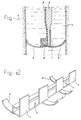
- Figure 1 shows a cross-section through the bottom part of an anchor according to the invention with insertion sheet and sheeting panel.
- Figure 2 shows a perspective view of the anchor.
- the steel anchor 1 shown in the figures is in the shape of a U of which one of the flanges is bent inwards at its top part for the purpose of forming a channel into which the thickened bottom edge 2 of a sheeting panel 3 is pushed.
- This sheeting panel is made of plastic, for example HDPE, and is connected in a manner which is known per se by edge locking sections to a sheeting panel already placed in the trenches.
- a steel insertion sheet for pressing the sheeting panel with anchor into a ground trench 4 filled with bentonite mixture is indicated by 5 and projects with its bottom edge into the anchor.
- centring wings 6 are fixed to the anchor 1, projecting on either side. These wings end in an upward-sloping part, so that during the downward movement of the anchor they cannot become jammed in the trench wall when they come into contact with said wall.
- the wings are welded to the bottom of the anchor section, but they can also be connected to the anchor section at other places.
- Vertical-running recesses 7 are provided in order to be able to adjust the local wedging between anchor section 1 and the insertion sheet 5. These recesses are preferably of a minimum breadth of 0.5 mm and a maximum breadth of 300 mm. They can continue into the bottom of the U.
Landscapes
- Engineering & Computer Science (AREA)
- Life Sciences & Earth Sciences (AREA)
- Environmental & Geological Engineering (AREA)
- Hydrology & Water Resources (AREA)
- General Life Sciences & Earth Sciences (AREA)
- Mining & Mineral Resources (AREA)
- Paleontology (AREA)
- Civil Engineering (AREA)
- General Engineering & Computer Science (AREA)
- Structural Engineering (AREA)
- Piles And Underground Anchors (AREA)
Claims (4)
- System, das einen U-förmig ausgebildeten Anker (1) für eine Abdeckplatte (3) und ein Einschubstahlelement (5) für den genannten Anker umfaßt, dadurch gekennzeichnet, daß das obere Stück von einem der Füße des U-förmig ausgebildeten Ankers zum anderen Fuß hin gebogen ausgeführt ist, um so eine Unterbringungskammer für ein verdicktes Teil (2) an der unteren Kante der Abdeckplatte zu bilden, daß ein Raum zwischen der freien Kante des nach innen gebogenen Fußteiles und dem anderen Fuß vorhanden ist, so daß sich die untere Kante des Einschubstahlelementes (5) durch diesen Raum bewegen kann, und daß eine Anzahl von im wesentlichen vertikalen Rücksprüngen (7) im Ankerabschnitt vorgesehen sind, wobei die genannten Rücksprünge von der freien Kante des genannten anderes Fußes aus verlaufen.
- System nach Anspruch 1, dadurch gekennzeichnet, daß die genannten Rücksprünge in einen Teil des Bodens des U-förmig ausgebildeten Ankers hinein verlaufen.
- System nach Anspruch 1 oder 2, dadurch gekennzeichnet, daß die Breite der Rücksprünge zwischen 0,5 und 300 mm beträgt.
- System nach einem der vorstehenden Ansprüche, dadurch gekennzeichnet, daß auf beiden Seiten hervorstehende Zentrierflügel (6) am Anker (1) befestigt sind.
Applications Claiming Priority (2)
| Application Number | Priority Date | Filing Date | Title |
|---|---|---|---|
| NL9000875 | 1990-04-12 | ||
| NL9000875A NL9000875A (nl) | 1990-04-12 | 1990-04-12 | Anker. |
Publications (2)
| Publication Number | Publication Date |
|---|---|
| EP0451925A1 EP0451925A1 (de) | 1991-10-16 |
| EP0451925B1 true EP0451925B1 (de) | 1993-07-14 |
Family
ID=19856923
Family Applications (1)
| Application Number | Title | Priority Date | Filing Date |
|---|---|---|---|
| EP19910200872 Expired - Lifetime EP0451925B1 (de) | 1990-04-12 | 1991-04-12 | Ankersystem |
Country Status (3)
| Country | Link |
|---|---|
| EP (1) | EP0451925B1 (de) |
| DE (1) | DE69100167T2 (de) |
| NL (1) | NL9000875A (de) |
Family Cites Families (3)
| Publication number | Priority date | Publication date | Assignee | Title |
|---|---|---|---|---|
| US3479933A (en) * | 1968-01-11 | 1969-11-25 | Brown Co D S | Elongated,hollow,elastomer sealing strip with elongated,laterally deformable spring |
| NL191153C (nl) * | 1981-09-15 | 1995-02-16 | Stevin Volker Beton Water | Werkwijze voor het vervaardigen van een de stroming van grondwater beperkend scherm in de grond alsmede vel en lans voor toepassing bij deze werkwijze. |
| DE3540270A1 (de) * | 1985-11-13 | 1987-05-14 | Wayss & Freytag Ag | Verfahren zur herstellung einer dichtwand und vorrichtung zur durchfuehrung des verfahrens |
-
1990
- 1990-04-12 NL NL9000875A patent/NL9000875A/nl not_active Application Discontinuation
-
1991
- 1991-04-12 EP EP19910200872 patent/EP0451925B1/de not_active Expired - Lifetime
- 1991-04-12 DE DE1991600167 patent/DE69100167T2/de not_active Expired - Fee Related
Also Published As
| Publication number | Publication date |
|---|---|
| NL9000875A (nl) | 1991-11-01 |
| DE69100167T2 (de) | 1993-10-28 |
| EP0451925A1 (de) | 1991-10-16 |
| DE69100167D1 (de) | 1993-08-19 |
Similar Documents
| Publication | Publication Date | Title |
|---|---|---|
| CA2495749C (en) | Reinforcing system for stackable retaining wall units | |
| US4699544A (en) | Protective frame device for drainage channel | |
| US5340234A (en) | Trench drain system and installation method | |
| US4384810A (en) | Locking beam to form a three-dimensional lattice in a construction system for plantable shoring walls | |
| EP0067551A1 (de) | Bewehrte Erdbauwerke und Verkleidungselemente dafür | |
| US5035095A (en) | Basement wall structure to prevent water leakage | |
| US5794393A (en) | Concrete foundation wall form apparatus and method | |
| US5399047A (en) | Trench forming assemblies having enhanced anchoring means | |
| EP1302598A2 (de) | Bewehrungsvorrichtung für ein stabelbares Stützmauersegment | |
| EP3362607B1 (de) | Wallsystem für bodenrückhaltung | |
| IE50212B1 (en) | Construction plate for a ditch construction device | |
| US3986310A (en) | Modular swimming pool structure and method for its erection | |
| US3064273A (en) | Swimming pool | |
| JPS6314124B2 (de) | ||
| EP0451925B1 (de) | Ankersystem | |
| US975665A (en) | Shoring. | |
| EP0041516A1 (de) | Konstruktion von flüssigkeitsbecken. | |
| US10508396B2 (en) | Water barrier element | |
| JP2548634B2 (ja) | 水底地盤打込み部材を用いた水域構造物 | |
| US20080170913A1 (en) | Seawall connector for attachment of geogrid material | |
| EP0026782B1 (de) | Erdreich- und wasserschutzmauer, die aus vorgefertigten plattenelementen zusammengesetzt ist | |
| EP0050166B1 (de) | Stützmauer | |
| JPS6033160Y2 (ja) | 土木建築用ブロツク | |
| JPH07127051A (ja) | 連続地中壁施工用鉄筋篭の構造及びその建込み方法 | |
| JPH0656001B2 (ja) | 土圧低減構造を有する壁体構築物 |
Legal Events
| Date | Code | Title | Description |
|---|---|---|---|
| PUAI | Public reference made under article 153(3) epc to a published international application that has entered the european phase |
Free format text: ORIGINAL CODE: 0009012 |
|
| AK | Designated contracting states |
Kind code of ref document: A1 Designated state(s): BE DE GB LU NL |
|
| 17P | Request for examination filed |
Effective date: 19911112 |
|
| 17Q | First examination report despatched |
Effective date: 19920427 |
|
| GRAA | (expected) grant |
Free format text: ORIGINAL CODE: 0009210 |
|
| AK | Designated contracting states |
Kind code of ref document: B1 Designated state(s): BE DE GB LU NL |
|
| REF | Corresponds to: |
Ref document number: 69100167 Country of ref document: DE Date of ref document: 19930819 |
|
| PLBE | No opposition filed within time limit |
Free format text: ORIGINAL CODE: 0009261 |
|
| STAA | Information on the status of an ep patent application or granted ep patent |
Free format text: STATUS: NO OPPOSITION FILED WITHIN TIME LIMIT |
|
| EPTA | Lu: last paid annual fee | ||
| 26N | No opposition filed | ||
| REG | Reference to a national code |
Ref country code: GB Ref legal event code: IF02 |
|
| PGFP | Annual fee paid to national office [announced via postgrant information from national office to epo] |
Ref country code: GB Payment date: 20050407 Year of fee payment: 15 |
|
| PGFP | Annual fee paid to national office [announced via postgrant information from national office to epo] |
Ref country code: BE Payment date: 20050421 Year of fee payment: 15 |
|
| PGFP | Annual fee paid to national office [announced via postgrant information from national office to epo] |
Ref country code: LU Payment date: 20050425 Year of fee payment: 15 |
|
| PGFP | Annual fee paid to national office [announced via postgrant information from national office to epo] |
Ref country code: DE Payment date: 20050427 Year of fee payment: 15 |
|
| PGFP | Annual fee paid to national office [announced via postgrant information from national office to epo] |
Ref country code: NL Payment date: 20050429 Year of fee payment: 15 |
|
| PG25 | Lapsed in a contracting state [announced via postgrant information from national office to epo] |
Ref country code: GB Free format text: LAPSE BECAUSE OF NON-PAYMENT OF DUE FEES Effective date: 20060412 |
|
| PG25 | Lapsed in a contracting state [announced via postgrant information from national office to epo] |
Ref country code: LU Free format text: LAPSE BECAUSE OF NON-PAYMENT OF DUE FEES Effective date: 20060430 Ref country code: BE Free format text: LAPSE BECAUSE OF NON-PAYMENT OF DUE FEES Effective date: 20060430 |
|
| PG25 | Lapsed in a contracting state [announced via postgrant information from national office to epo] |
Ref country code: NL Free format text: LAPSE BECAUSE OF NON-PAYMENT OF DUE FEES Effective date: 20061101 Ref country code: DE Free format text: LAPSE BECAUSE OF NON-PAYMENT OF DUE FEES Effective date: 20061101 |
|
| GBPC | Gb: european patent ceased through non-payment of renewal fee |
Effective date: 20060412 |
|
| NLV4 | Nl: lapsed or anulled due to non-payment of the annual fee |
Effective date: 20061101 |
|
| BERE | Be: lapsed |
Owner name: HOLLANDSCHE *BETON GROEP N.V. Effective date: 20060430 |