EP0449928B1 - Raccord de tubes - Google Patents
Raccord de tubes Download PDFInfo
- Publication number
- EP0449928B1 EP0449928B1 EP90900954A EP90900954A EP0449928B1 EP 0449928 B1 EP0449928 B1 EP 0449928B1 EP 90900954 A EP90900954 A EP 90900954A EP 90900954 A EP90900954 A EP 90900954A EP 0449928 B1 EP0449928 B1 EP 0449928B1
- Authority
- EP
- European Patent Office
- Prior art keywords
- pipe
- segments
- gripping
- ring
- coupling according
- Prior art date
- Legal status (The legal status is an assumption and is not a legal conclusion. Google has not performed a legal analysis and makes no representation as to the accuracy of the status listed.)
- Expired - Lifetime
Links
Images


Classifications
-
- F—MECHANICAL ENGINEERING; LIGHTING; HEATING; WEAPONS; BLASTING
- F16—ENGINEERING ELEMENTS AND UNITS; GENERAL MEASURES FOR PRODUCING AND MAINTAINING EFFECTIVE FUNCTIONING OF MACHINES OR INSTALLATIONS; THERMAL INSULATION IN GENERAL
- F16L—PIPES; JOINTS OR FITTINGS FOR PIPES; SUPPORTS FOR PIPES, CABLES OR PROTECTIVE TUBING; MEANS FOR THERMAL INSULATION IN GENERAL
- F16L21/00—Joints with sleeve or socket
- F16L21/08—Joints with sleeve or socket with additional locking means
-
- F—MECHANICAL ENGINEERING; LIGHTING; HEATING; WEAPONS; BLASTING
- F16—ENGINEERING ELEMENTS AND UNITS; GENERAL MEASURES FOR PRODUCING AND MAINTAINING EFFECTIVE FUNCTIONING OF MACHINES OR INSTALLATIONS; THERMAL INSULATION IN GENERAL
- F16L—PIPES; JOINTS OR FITTINGS FOR PIPES; SUPPORTS FOR PIPES, CABLES OR PROTECTIVE TUBING; MEANS FOR THERMAL INSULATION IN GENERAL
- F16L19/00—Joints in which sealing surfaces are pressed together by means of a member, e.g. a swivel nut, screwed on or into one of the joint parts
- F16L19/08—Joints in which sealing surfaces are pressed together by means of a member, e.g. a swivel nut, screwed on or into one of the joint parts with metal rings which bite into the wall of the pipe
- F16L19/083—Joints in which sealing surfaces are pressed together by means of a member, e.g. a swivel nut, screwed on or into one of the joint parts with metal rings which bite into the wall of the pipe the longitudinal cross-section of the ring not being modified during clamping
-
- F—MECHANICAL ENGINEERING; LIGHTING; HEATING; WEAPONS; BLASTING
- F16—ENGINEERING ELEMENTS AND UNITS; GENERAL MEASURES FOR PRODUCING AND MAINTAINING EFFECTIVE FUNCTIONING OF MACHINES OR INSTALLATIONS; THERMAL INSULATION IN GENERAL
- F16L—PIPES; JOINTS OR FITTINGS FOR PIPES; SUPPORTS FOR PIPES, CABLES OR PROTECTIVE TUBING; MEANS FOR THERMAL INSULATION IN GENERAL
- F16L25/00—Constructive types of pipe joints not provided for in groups F16L13/00 - F16L23/00 ; Details of pipe joints not otherwise provided for, e.g. electrically conducting or insulating means
- F16L25/10—Sleeveless joints between two pipes, one being introduced into the other
-
- F—MECHANICAL ENGINEERING; LIGHTING; HEATING; WEAPONS; BLASTING
- F16—ENGINEERING ELEMENTS AND UNITS; GENERAL MEASURES FOR PRODUCING AND MAINTAINING EFFECTIVE FUNCTIONING OF MACHINES OR INSTALLATIONS; THERMAL INSULATION IN GENERAL
- F16L—PIPES; JOINTS OR FITTINGS FOR PIPES; SUPPORTS FOR PIPES, CABLES OR PROTECTIVE TUBING; MEANS FOR THERMAL INSULATION IN GENERAL
- F16L47/00—Connecting arrangements or other fittings specially adapted to be made of plastics or to be used with pipes made of plastics
- F16L47/04—Connecting arrangements or other fittings specially adapted to be made of plastics or to be used with pipes made of plastics with a swivel nut or collar engaging the pipe
Definitions
- the present invention relates to a pipe coupling for connecting a pipe to a fitting.
- the pipes are generally circular in cross-section and the fittings may be of a variety of forms, for example fittings to interconnect two pipes end to end, fittings to connect a pipe to devices such as valve housings, and fitting to form elbows, T-junctions or the like.
- the present invention is applicable to any situations in which one end of a pipe has to be connected to any other component.
- Couplings have been devised which incorporate a sealing ring that not only provides a good fluid-type seal between the fitting and the pipe but also grip the pipe end to provide enhanced pull-out resistance.
- a sealing ring is described in British Patent Specification GB 2167145.
- a sealing ring is described which is fabricated from a resilient material in which gripping members are embedded.
- the coupling is assembled the sealing ring is compressed in such a manner that the gripping members are biased radially inwards against the outer wall of the pipe.
- the manufacture of such sealing rings incorporating embedded gripping members is however a relatively complex procedure and as a result the couplings are relatively expensive. This is of particular importance where a full range of couplings must be provided to enable the user to select from the range couplings appropriate to a variety of different pipe diameters. economiess of scale are therefore difficult to achieve.
- US-A-3744824 discloses a pipe coupling in which gripping elements are carried on a resilient ring.
- a pipe coupling for connecting a pipe to a fitting, the coupling comprising an annular assembly incorporating a gripping ring for insertion into a radial gap between the pipe and the fitting, and means for applying an axial load to the annular assembly so that the gripping ring is biased radially against the pipe, wherein the gripping ring is defined by a plurality of separable segments, adjacent segments of the gripping ring being directly interlocked, and at least a plurality of the segments are gripping segments which are dimensioned such that when the annular assembly is axially compressed the gripping segments are biased against the pipes.
- adjacent segments in the gripping ring may be interlocked by loose dovetail interengaging formations.
- Each segment may be a gripping segment, or alternatively a plurality of spacer segments may be provided, adjacent gripping segments in the gripping ring being interconnected by spacer segments with which the gripping segments are interlocked.
- the annular assembly comprises a resilient sealing ring.
- a force transmitting ring is preferably interposed between the gripping ring and the sealing ring.
- the force transmitting ring and the sealing ring could be incorporated together so that only one component part would be required in the annular assembly to perform both sealing and force transmission functions.
- the fitting may define a housing into which one end of the pipe is inserted, the annular assembly extending around the pipe inside the housing.
- the fitting may comprise an annular housing having a first end which is in sliding engagement with the socket and a second end defining a shoulder extending radially inwards and facing towards the first end, the sealing ring being received within the first end of the housing, the gripping ring being located between the sealing ring and the shoulder, and the axial load applying means comprising means for forcing the shoulder of the annular housing towards the socket so as to compress the annular assembly between the socket and the said shoulder.
- the fitting may comprise a tubular body one end of which is inserted in the end of the pipe, the annular assembly extending around the tubular body inside the pipe.
- the tubular body may have a radially outwardly extending shoulder adjacent its said end, and the axial load applying means may comprise means connected to the tubular body for pushing the annular assembly against the said shoulder.
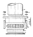
- the coupling comprises an annular housing 1 in which is received an annular assembly incorporating a resilient sealing ring 2, a metal ring 3, and a gripping ring made up from a plurality of individual segments 4.
- the annular housing 1 engages a tubular socket 5, the housing 1 and socket 5 defining a fitting to which a pipe 6 is to be connected.
- the fitting of which the socket 5 forms a part may be of any type and could be for example a straight connector for interconnecting two pipes end to end, in which case the components illustrated in Fig. 1 are duplicated at either end of the socket 5.
- the pipe 6 is of polyethylene and accordingly a metal insert 7 is provided in the pipe end to prevent the pipe end fro collapsing radially inwards.
- Tension bolts 8 extend through the annular housing 1 such that when nuts 9 are tightened the annular assembly is pulled against the socket 5 .
- the end of the annular housing 1 adjacent the socket 5 is a loose sliding fit over the socket 5.
- Fig. 2 is an exploded view of the components shown in Fig. 1 and Fig. 3 is a section through Fig. 1 on the line III-III.
- Fig. 4 illustrates two of the gripping segments 4 and it can be seen that each of the gripping segments is identical and incorporates a tongue 10 with an enlarged end and a keyhole-section socket 11 into which the tongue 10 of an adjacent segment can be lipped in the axial direction. This is one example of a "dovetail" type interengagement between segments.
- each of the segments can move relative to its two neighbours in both the axial and circumferential directions.
- the side of each segment facing the pipe 6 is provided with serrations 12.
- the sealing ring 2 in its free state defines a peripheral lip 13 extending radially outwards from a main body 14 which is of generally triangular cross-section.
- a groove 15 reduces the pressure required to cause some axial displacement between the lip 13 and the body 14.
- An inclined surface 16 is in use positioned adjacent the ring 3.
- An inner lip 17 has a diameter less than that of the minimum expected diameter of the pipe 7 onto which the assembly is to be fitted.
- the assembly comprising the housing 1, the sealing ring 2, the ring 3 and the gripping segments 4 is simply slipped over the pipe end.
- the segments 4 are only loosely retained within the housing they easily ride up over the end of the pipe and are prevented from being pushed out of the assembly by the engagement between the sealing ring lip 13 and the mating groove 18 in the housing 1.
- the sealing ring is initially distorted as a result of the internal diameter of the sealing ring being less than that of the pipe.
- the pipe end is then inserted into the socket 5, the bolts 8 are inserted and the nuts 9 are tightened up. This pulls the annular assembly onto the socket 5.
- the gripping ring is in the form of a series of segments 4 and can easily be pulled over even a distorted pipe of oval cross-section.
- the resistance to forces tending to pull the pipe away from the fitting is very large, typically grater than that required to result in failure of a polyethylene pipe for example.
- Fig. 7 illustrates an alternative embodiment of the invention suitable for forming a seal with the inner wall of a pipe.
- a pipe 20 receives a tubular fitting body 21 around which are positioned a sealing ring 22, a force transmitting ring 23, segments 24 (which may be identical to those illustrated in Fig. 4), a tubular push ring 25, and a nut 26 engaging a thread 27 provided on the body 21.
- the nut 26 can be tightened to apply an axial load to the ring assembly, thereby compressing the sealing ring against a shoulder 28 supported in the body 21.
- the axial load also forces the segments 24 radially outwards to grip the pipe 20.
- a significant advantage of the described arrangements is that gripping rings of different nominal diameter can be produced simply by adjusting the number of segments in each gripping ring.
- a single basic component can be used to form gripping rings suitable for a wide range of nominal pipe diameters. It is of course necessary to provide sealing rings and force transmitting rings matched to the particular pipe size but as these components are fabricated from a single material this can be done relatively cheaply.
- the coupling in accordance with the present invention can be fabricated from any suitable material.
- the gripping segments may be moulded from a hard plastics material such as acetal or fabricated from any appropriate metal.
- the sealing ring can be fabricated from any suitable elastomeric material.
- the invention can be used with plastics piping such as polyethylene or any other type of piping such as steel or other metal materials.
- the force transmitting ring interposed between the sealing and gripping rings may be manufactured from metal or a hard plastics material and may be supplied adhered to the sealing ring. Any appropriate mechanism may be provided for compressing the annular assembly, for example arrangements such as those shown in the accompanying drawings or any other arrangement capable of providing axial and radial compression.
- the couplings are also capable of resisting pressure fluctuations in which the internal pipe pressure is greater than or less than the external pressure. Furthermore more than one sealing ring and more than one gripping ring can be provided if this is required to meet operating conditions.
- the couplings are applicable in systems carrying gases, liquids, solids or combinations thereof, and can be supplied to the end user with the ring components ready assembled.
Abstract
Claims (10)
- Un raccord pour tuyaux destiné à raccorder un tuyau à une pièce de raccordement, le raccord comprenant un assemblage annulaire comportant une bague de serrage devant être insérée dans un intervalle radial entre le tuyau et la pièce de raccordement, et un moyen d'application d'une charge axiale sur l'assemblage annulaire de sorte que la bague de serrage soit poussée radialement contre le tuyau, dans lequel la bague de serrage est définie par une pluralité de segments capables de séparation, les segments adjacents de la bague de serrage étant en prise mutuelle directe, et au moins une pluralité des segments sont des serpents de serrage qui sont dimensionnés de telle façon que lorsque l'assemblage annulaire est comprimé axialement les segments de serrage sont poussés contre les tuyaux.
- Un raccord pour tuyaux selon la revendication 1, dans lequel des serpents adjacents dans la bague de serrage sont en prise mutuelle directe par des formations à engagement mutuel amovibles à queue d'aronde.
- Un raccord pour tuyaux selon une revendication précédente quelconque, dans lequel chaque segment est un dit segment de serrage.
- Un raccord pour tuyaux selon la revendication 1 ou 2, dans lequel une pluralité des segments sont des segments d'espacement, des segments adjacents de serrage dans la bague de serrage étant raccordés mutuellement par des serpents d'espacement avec lesquels les segments de serrage sont en prise mutuelle.
- Un raccord pour deux tuyaux selon une revendication précédente quelconque, dans lequel l'assemblage annulaire comprend une bague d'étanchéité élastique.
- Un raccord pour tuyaux selon la revendication 5, comprenant une bague de transmission de force interposée entre la bague de serrage et la bague d'étanchéité.
- Un raccord pour tuyaux selon la revendication 5 ou 6, dans lequel la pièce de raccordement définit un logement dans lequel une extrémité du tuyau est introduite, et l'assemblage annulaire se prolonge autour du tuyau à l'intérieur du logement.
- Un raccord pour tuyaux selon la revendication 7, dans lequel la pièce de raccordement comprend un logement annulaire présentant une première extrémité qui se trouve en engagement coulissant avec l'emboîtement et une deuxième extrémité définissant un épaulement se prolongeant radialement vers l'intérieur et faisant face à la première extrémité, la bague d'étanchéité est reçue dans la première extrémité du logement, la bague de serrage est située entre la bague d'étanchéité et l'épaulement, et le moyen d'application de charge axiale comporte un moyen pour forcer l'épaulement du logement annulaire vers l'emboîtement de manière à comprimer l'assemblage annulaire entre l'emboîtement et ledit épaulement.
- Un raccord pour tuyaux selon la revendication 3 ou 6, dans lequel la pièce de raccordement comporte un corps tubulaire dont une extrémité est insérée dans l'extrémité du tuyau, et l'assemblage annulaire se prolonge autour du corps tubulaire à l'intérieur du tuyau.
- Un raccord pour tuyaux selon la revendication 9, dans lequel le corps tubulaire présente un épaulement se prolongeant radialement vers l'extérieur adjacent à sa dite extrémité, et le moyen d'application de charge axiale comprend un moyen raccordé au corps tubulaire pour pousser l'assemblage annulaire contre ledit épaulement.
Priority Applications (1)
| Application Number | Priority Date | Filing Date | Title |
|---|---|---|---|
| AT90900954T ATE89062T1 (de) | 1988-12-23 | 1989-12-20 | Rohrkupplung. |
Applications Claiming Priority (2)
| Application Number | Priority Date | Filing Date | Title |
|---|---|---|---|
| GB888830202A GB8830202D0 (en) | 1988-12-23 | 1988-12-23 | Pipe coupling |
| GB8830202 | 1988-12-23 |
Publications (2)
| Publication Number | Publication Date |
|---|---|
| EP0449928A1 EP0449928A1 (fr) | 1991-10-09 |
| EP0449928B1 true EP0449928B1 (fr) | 1993-05-05 |
Family
ID=10649142
Family Applications (1)
| Application Number | Title | Priority Date | Filing Date |
|---|---|---|---|
| EP90900954A Expired - Lifetime EP0449928B1 (fr) | 1988-12-23 | 1989-12-20 | Raccord de tubes |
Country Status (6)
| Country | Link |
|---|---|
| US (1) | US5188401A (fr) |
| EP (1) | EP0449928B1 (fr) |
| AU (1) | AU4812090A (fr) |
| ES (1) | ES2040592T3 (fr) |
| GB (2) | GB8830202D0 (fr) |
| WO (1) | WO1990007671A1 (fr) |
Families Citing this family (38)
| Publication number | Priority date | Publication date | Assignee | Title |
|---|---|---|---|---|
| JP2670956B2 (ja) * | 1992-12-28 | 1997-10-29 | アズマ工業 株式会社 | 真空掃除機における吸引用補長管の接続機構 |
| GB2304163B (en) * | 1995-08-05 | 1999-03-17 | Uponor Ltd | Pipe joint and electrofusion coupling therefor |
| US5956920A (en) | 1997-08-25 | 1999-09-28 | L.B. Plastics Limited | Modular post cladding element, post cladding assembly, and method of cladding a post |
| NL1002514C2 (nl) | 1996-03-04 | 1997-09-05 | Fischer Georg Waga Nv | Koppelinrichting. |
| US6264395B1 (en) * | 2000-02-04 | 2001-07-24 | Jerry P. Allamon | Slips for drill pipe or other tubular goods |
| GB2363437B (en) * | 2000-06-13 | 2004-08-11 | Glynwed Pipe Systems Ltd | Method and apparatus for coupling pipe ends and a sealing and gripping assembly for the apparatus |
| US7415982B1 (en) * | 2001-02-15 | 2008-08-26 | Sheridan Timothy B | Smokeless pipe |
| GB2377736A (en) * | 2001-07-18 | 2003-01-22 | Saint Gobain Pipelines Plc | A pipe coupling |
| US7267372B2 (en) * | 2001-10-11 | 2007-09-11 | Pi-Thon Designs, Inc. | Tube connector |
| CN1271361C (zh) * | 2002-12-21 | 2006-08-23 | Kulm控股股份公司 | 螺纹式管接头 |
| DE20219884U1 (de) * | 2002-12-21 | 2004-04-22 | Kulm Holding Ag | Rohrverschraubung |
| US7374212B1 (en) * | 2003-03-21 | 2008-05-20 | Arlington Industries, Inc. | Rain tight fitting |
| US6974160B2 (en) * | 2003-05-19 | 2005-12-13 | S&B Technical Products, Inc. | Self restraining gasket and pipe joint |
| FR2866094A1 (fr) * | 2004-02-06 | 2005-08-12 | Banides & Debeaurain Ets | Raccord mecanique destine a assurer la solidarisation d'un tuyau en matiere plastique a un appareil de robinetterie |
| US20090101328A1 (en) | 2004-09-28 | 2009-04-23 | Advanced Composite Products & Technology, Inc. | Composite drill pipe and method of forming same |
| US7458617B2 (en) * | 2004-09-28 | 2008-12-02 | Advanced Composite Products & Technology, Inc. | Composite drill pipe |
| NL1030404C2 (nl) | 2005-11-11 | 2007-05-14 | Fischer Georg Waga Nv | Koppelinrichting voor een buis. |
| US20080149873A1 (en) * | 2006-12-20 | 2008-06-26 | Cimberio Valve Co., Inc. | Valve with push-fit connection |
| US7950701B2 (en) | 2007-05-15 | 2011-05-31 | Victaulic Company | Pipe coupling having movable gripping bodies |
| JP4441549B2 (ja) | 2007-06-12 | 2010-03-31 | 株式会社水道技術開発機構 | 管継手部の離脱防止装置 |
| JP4429347B2 (ja) * | 2007-09-18 | 2010-03-10 | 富士通テン株式会社 | ミリ波レーダ装置のバイアス調整方法 |
| US7837238B2 (en) * | 2009-01-12 | 2010-11-23 | Krausz Industries Development Ltd | Pipe grip ring |
| NL2002683C2 (en) * | 2009-03-30 | 2010-10-04 | Fischer Georg Waga Nv | A coupling device. |
| GB2474899B (en) * | 2009-10-30 | 2016-02-03 | Crane Ltd | Improved pipe coupling |
| GB201000125D0 (en) * | 2010-01-05 | 2010-02-17 | Haywood Tyler Group Ltd | Grip ring |
| AT509694B1 (de) | 2010-04-01 | 2012-02-15 | E Hawle Armaturenwerke Gmbh | Rohrverbindungsvorrichtung |
| FR2965023B1 (fr) * | 2010-09-17 | 2013-11-29 | Peugeot Citroen Automobiles Sa | Dispositif d'assemblage d'une durite et d'un sous-ensemble mecanique, en particulier sur un vehicule automobile |
| US9157643B2 (en) | 2010-10-14 | 2015-10-13 | Fimcim S.P.A. | Conditioning plant |
| US8556302B2 (en) | 2011-04-05 | 2013-10-15 | Victaulic Company | Pivoting pipe coupling having a movable gripping body |
| GB201117049D0 (en) * | 2011-10-04 | 2011-11-16 | Ecolok Ltd | Method and apparatus for gripping |
| NL2009953C2 (en) * | 2012-12-10 | 2014-06-11 | Fischer Georg Waga Nv | A coupling device for a tube. |
| US9086177B2 (en) * | 2012-12-17 | 2015-07-21 | Eliezer Krausz Industrial Development Ltd. | Jointed bridge for clamp assembly |
| US9400071B1 (en) * | 2014-06-04 | 2016-07-26 | Mcwane, Inc. | Pipe joint gasket with articulating anti-slip segments |
| US11110573B2 (en) | 2016-11-17 | 2021-09-07 | Daniel A. Faro, Sr. | Push-fit de-coupling tool |
| US10342958B2 (en) | 2017-06-30 | 2019-07-09 | Abbott Cardiovascular Systems Inc. | System and method for correcting valve regurgitation |
| NL2023367B1 (en) * | 2019-06-24 | 2021-02-01 | Pipelife Nederland Bv | Coupling assembly |
| CN114222883A (zh) * | 2020-04-30 | 2022-03-22 | 东洋克斯株式会社 | 管接头用套筒及具备该管接头用套筒的管接头 |
| DE102022116679A1 (de) | 2022-07-05 | 2024-01-11 | Viega Technology Gmbh & Co. Kg | Klemmring für einen Fitting und Fitting mit einem Klemmring |
Family Cites Families (21)
| Publication number | Priority date | Publication date | Assignee | Title |
|---|---|---|---|---|
| US1788366A (en) * | 1929-09-03 | 1931-01-13 | Appleton Electric Co | Adjustable connecter |
| GB611051A (en) * | 1945-08-07 | 1948-10-25 | Albert Wilburn Miller | Detachable coupling for pipes, tubes or other elongated members |
| GB760290A (en) * | 1954-09-22 | 1956-10-31 | Sun Engineering Richmond Ltd | Improvements in or relating to pipe joints or pipe couplings |
| GB944590A (en) * | 1960-04-20 | 1963-12-18 | Cie Metaux Doverpelt Lommel | Improvements in and relating to the condensation of metal vapours |
| US3158388A (en) * | 1962-07-13 | 1964-11-24 | Dixon Valve & Coupling Co | Hose coupling connection |
| US3189962A (en) * | 1962-11-07 | 1965-06-22 | Amp Inc | Clamping device |
| GB994590A (en) * | 1963-03-08 | 1965-06-10 | Gas Council | Improvements in pipe couplings |
| US3679239A (en) * | 1971-06-25 | 1972-07-25 | Mcdonald Mfg Co A Y | Compression coupling for plastic pipe |
| US3744824A (en) * | 1972-06-26 | 1973-07-10 | Graenges Essem Ab | Pipe couplings |
| CH555026A (de) * | 1972-08-14 | 1974-10-15 | Oetiker Hans | Verbindungsanordnung zwischen einem rohrstutzen und einem diesen umfassenden schlauch. |
| US4006921A (en) * | 1975-06-10 | 1977-02-08 | Hydrotech International, Inc. | Pipe coupling |
| CH595578A5 (fr) * | 1975-12-01 | 1978-02-15 | Endermill Anstalt | |
| US4062572A (en) * | 1976-08-30 | 1977-12-13 | Inner-Tite, A Division Of Yara Engineering Corporation | Transition fittings |
| CA1069959A (fr) * | 1976-11-01 | 1980-01-15 | Charles E. Felker | Raccords pour tubes et tuyaux |
| NZ188004A (en) * | 1977-08-05 | 1982-02-23 | Philmac Pty Ltd | Polymeric pipe fitting locking ring maintains constant pressure on deformable seal |
| DE2852420C2 (de) * | 1978-12-04 | 1981-02-26 | Gebrueder Buehler Ag, Uzwil (Schweiz) | Futterwürfelpresse |
| FR2525727B1 (fr) * | 1982-04-26 | 1986-12-05 | Contraves Ag | Manchon pour l'assemblage emmanchable de tuyaux |
| SE8204648D0 (sv) * | 1982-08-11 | 1982-08-11 | Andrzej Tomasz Iwanicki | Rorkoppling |
| GB2167145B (en) * | 1984-11-21 | 1988-12-21 | Victaulic Plc | Improvements in or relating to pipe couplings and pipe joints formed therewith |
| JPS62130286U (fr) * | 1986-02-07 | 1987-08-17 | ||
| US5037144A (en) * | 1990-05-02 | 1991-08-06 | Amsted Industries Incorporated | Restrained pipe joint |
-
1988
- 1988-12-23 GB GB888830202A patent/GB8830202D0/en active Pending
-
1989
- 1989-12-20 EP EP90900954A patent/EP0449928B1/fr not_active Expired - Lifetime
- 1989-12-20 WO PCT/GB1989/001514 patent/WO1990007671A1/fr active IP Right Grant
- 1989-12-20 ES ES199090900954T patent/ES2040592T3/es not_active Expired - Lifetime
- 1989-12-20 AU AU48120/90A patent/AU4812090A/en not_active Abandoned
- 1989-12-20 US US07/688,560 patent/US5188401A/en not_active Expired - Lifetime
- 1989-12-21 GB GB8928858A patent/GB2227067B/en not_active Expired - Lifetime
Also Published As
| Publication number | Publication date |
|---|---|
| GB8928858D0 (en) | 1990-02-28 |
| US5188401A (en) | 1993-02-23 |
| AU4812090A (en) | 1990-08-01 |
| GB2227067A (en) | 1990-07-18 |
| WO1990007671A1 (fr) | 1990-07-12 |
| GB2227067B (en) | 1992-09-16 |
| EP0449928A1 (fr) | 1991-10-09 |
| ES2040592T3 (es) | 1993-10-16 |
| GB8830202D0 (en) | 1989-02-22 |
Similar Documents
| Publication | Publication Date | Title |
|---|---|---|
| EP0449928B1 (fr) | Raccord de tubes | |
| EP1292792B1 (fr) | Dispositif servant a accoupler une canalisation | |
| US5425557A (en) | Apparatus for and method of attaching hoses and tubes to a fitting | |
| US3637239A (en) | Thrust-resistant pipe joint | |
| US7207606B2 (en) | Mechanical pipe joint, gasket, and method for restraining pipe spigots in mechanical pipe joint bell sockets | |
| EP2959201B1 (fr) | Organe d'accouplement présentant des nervures de rigidité arquées | |
| CA1073497A (fr) | Raccord rapide | |
| US3815940A (en) | Joint for smooth end or flareless pipe | |
| US3813115A (en) | Plastic pipe thrust resistant joint | |
| US4923226A (en) | Apparatus for attaching a hose to a fitting | |
| US6439617B1 (en) | Coupler for a pipe or hose section | |
| EA004842B1 (ru) | Соединительная муфта для труб | |
| GB2032560A (en) | Coupling for a pipe | |
| GB2088001A (en) | Convoluted hose fitting | |
| GB2041131A (en) | Fluid tight releasable coupling | |
| US5261706A (en) | Apparatus for attaching a hose to a fitting | |
| WO2008074378A1 (fr) | Dispositif d'accouplement de tubes | |
| WO2014116741A1 (fr) | Systèmes de retenue pour tuyau évasé | |
| CA2283555C (fr) | Raccord de transition metallique de tuyau en plastique | |
| GB1591743A (en) | Pipe couplings | |
| EP1350051B1 (fr) | Element de raccord pour tuyaux en polymere comprenant une surface de butee pour le tuyau | |
| WO1996024003A1 (fr) | Connecteurs | |
| US3726548A (en) | Pipe fitting | |
| EP1164325A2 (fr) | Raccord de tuyaux | |
| GB2231931A (en) | Pipe couplings |
Legal Events
| Date | Code | Title | Description |
|---|---|---|---|
| PUAI | Public reference made under article 153(3) epc to a published international application that has entered the european phase |
Free format text: ORIGINAL CODE: 0009012 |
|
| 17P | Request for examination filed |
Effective date: 19910621 |
|
| AK | Designated contracting states |
Kind code of ref document: A1 Designated state(s): AT BE CH DE ES FR GB IT LI LU NL SE |
|
| 17Q | First examination report despatched |
Effective date: 19920204 |
|
| RBV | Designated contracting states (corrected) |
Designated state(s): AT BE CH DE ES FR IT LI LU NL SE |
|
| GRAA | (expected) grant |
Free format text: ORIGINAL CODE: 0009210 |
|
| AK | Designated contracting states |
Kind code of ref document: B1 Designated state(s): AT BE CH DE ES FR IT LI LU NL SE |
|
| PG25 | Lapsed in a contracting state [announced via postgrant information from national office to epo] |
Ref country code: SE Effective date: 19930505 Ref country code: LI Effective date: 19930505 Ref country code: CH Effective date: 19930505 Ref country code: AT Effective date: 19930505 |
|
| REF | Corresponds to: |
Ref document number: 89062 Country of ref document: AT Date of ref document: 19930515 Kind code of ref document: T |
|
| ITF | It: translation for a ep patent filed |
Owner name: BUGNION S.P.A. |
|
| REF | Corresponds to: |
Ref document number: 68906398 Country of ref document: DE Date of ref document: 19930609 |
|
| ET | Fr: translation filed | ||
| REG | Reference to a national code |
Ref country code: CH Ref legal event code: PL |
|
| REG | Reference to a national code |
Ref country code: ES Ref legal event code: FG2A Ref document number: 2040592 Country of ref document: ES Kind code of ref document: T3 |
|
| PGFP | Annual fee paid to national office [announced via postgrant information from national office to epo] |
Ref country code: FR Payment date: 19931209 Year of fee payment: 5 |
|
| PGFP | Annual fee paid to national office [announced via postgrant information from national office to epo] |
Ref country code: ES Payment date: 19931222 Year of fee payment: 5 |
|
| PGFP | Annual fee paid to national office [announced via postgrant information from national office to epo] |
Ref country code: DE Payment date: 19931227 Year of fee payment: 5 |
|
| PG25 | Lapsed in a contracting state [announced via postgrant information from national office to epo] |
Ref country code: LU Free format text: LAPSE BECAUSE OF NON-PAYMENT OF DUE FEES Effective date: 19931231 |
|
| PGFP | Annual fee paid to national office [announced via postgrant information from national office to epo] |
Ref country code: NL Payment date: 19931231 Year of fee payment: 5 |
|
| PGFP | Annual fee paid to national office [announced via postgrant information from national office to epo] |
Ref country code: BE Payment date: 19940131 Year of fee payment: 5 |
|
| PLBE | No opposition filed within time limit |
Free format text: ORIGINAL CODE: 0009261 |
|
| STAA | Information on the status of an ep patent application or granted ep patent |
Free format text: STATUS: NO OPPOSITION FILED WITHIN TIME LIMIT |
|
| 26N | No opposition filed | ||
| PG25 | Lapsed in a contracting state [announced via postgrant information from national office to epo] |
Ref country code: BE Effective date: 19941231 |
|
| BERE | Be: lapsed |
Owner name: WASK-RMF LTD Effective date: 19941231 |
|
| PG25 | Lapsed in a contracting state [announced via postgrant information from national office to epo] |
Ref country code: NL Effective date: 19950701 |
|
| PG25 | Lapsed in a contracting state [announced via postgrant information from national office to epo] |
Ref country code: FR Effective date: 19950831 |
|
| NLV4 | Nl: lapsed or anulled due to non-payment of the annual fee |
Effective date: 19950701 |
|
| PG25 | Lapsed in a contracting state [announced via postgrant information from national office to epo] |
Ref country code: DE Effective date: 19950901 |
|
| REG | Reference to a national code |
Ref country code: FR Ref legal event code: ST |
|
| PG25 | Lapsed in a contracting state [announced via postgrant information from national office to epo] |
Ref country code: ES Free format text: LAPSE BECAUSE OF NON-PAYMENT OF DUE FEES Effective date: 19951221 |
|
| REG | Reference to a national code |
Ref country code: ES Ref legal event code: FD2A Effective date: 19960113 |
|
| PG25 | Lapsed in a contracting state [announced via postgrant information from national office to epo] |
Ref country code: IT Free format text: LAPSE BECAUSE OF NON-PAYMENT OF DUE FEES;WARNING: LAPSES OF ITALIAN PATENTS WITH EFFECTIVE DATE BEFORE 2007 MAY HAVE OCCURRED AT ANY TIME BEFORE 2007. THE CORRECT EFFECTIVE DATE MAY BE DIFFERENT FROM THE ONE RECORDED. Effective date: 20051220 |