EP0449705B1 - Roboterwerkzeug zum Setzen von ringförmigen Profilen - Google Patents
Roboterwerkzeug zum Setzen von ringförmigen Profilen Download PDFInfo
- Publication number
- EP0449705B1 EP0449705B1 EP91400760A EP91400760A EP0449705B1 EP 0449705 B1 EP0449705 B1 EP 0449705B1 EP 91400760 A EP91400760 A EP 91400760A EP 91400760 A EP91400760 A EP 91400760A EP 0449705 B1 EP0449705 B1 EP 0449705B1
- Authority
- EP
- European Patent Office
- Prior art keywords
- small wheel
- tool
- tool according
- jack
- slugs
- Prior art date
- Legal status (The legal status is an assumption and is not a legal conclusion. Google has not performed a legal analysis and makes no representation as to the accuracy of the status listed.)
- Expired - Lifetime
Links
- 238000011144 upstream manufacturing Methods 0.000 claims description 2
- 241000237858 Gastropoda Species 0.000 claims 4
- 210000005069 ears Anatomy 0.000 description 5
- 238000009434 installation Methods 0.000 description 3
- 230000000694 effects Effects 0.000 description 2
- 230000008878 coupling Effects 0.000 description 1
- 238000010168 coupling process Methods 0.000 description 1
- 238000005859 coupling reaction Methods 0.000 description 1
- 238000010586 diagram Methods 0.000 description 1
- 238000006073 displacement reaction Methods 0.000 description 1
- 238000003032 molecular docking Methods 0.000 description 1
- 230000002441 reversible effect Effects 0.000 description 1
- 125000006850 spacer group Chemical group 0.000 description 1
Images


Classifications
-
- B—PERFORMING OPERATIONS; TRANSPORTING
- B23—MACHINE TOOLS; METAL-WORKING NOT OTHERWISE PROVIDED FOR
- B23P—METAL-WORKING NOT OTHERWISE PROVIDED FOR; COMBINED OPERATIONS; UNIVERSAL MACHINE TOOLS
- B23P19/00—Machines for simply fitting together or separating metal parts or objects, or metal and non-metal parts, whether or not involving some deformation; Tools or devices therefor so far as not provided for in other classes
- B23P19/04—Machines for simply fitting together or separating metal parts or objects, or metal and non-metal parts, whether or not involving some deformation; Tools or devices therefor so far as not provided for in other classes for assembling or disassembling parts
- B23P19/047—Machines for simply fitting together or separating metal parts or objects, or metal and non-metal parts, whether or not involving some deformation; Tools or devices therefor so far as not provided for in other classes for assembling or disassembling parts for flexible profiles, e.g. sealing or decorating strips in grooves or on other profiles by devices moving along the flexible profile
-
- B—PERFORMING OPERATIONS; TRANSPORTING
- B60—VEHICLES IN GENERAL
- B60J—WINDOWS, WINDSCREENS, NON-FIXED ROOFS, DOORS, OR SIMILAR DEVICES FOR VEHICLES; REMOVABLE EXTERNAL PROTECTIVE COVERINGS SPECIALLY ADAPTED FOR VEHICLES
- B60J10/00—Sealing arrangements
- B60J10/45—Assembling sealing arrangements with vehicle parts
Definitions
- Seals fitted on a motor vehicle door frame rebate can be open, that is to say rectilinear with a length equal to that of the periphery of the rebate, or else closed, that is to say annulars. See for example document US-A-47 80 943.
- the present invention relates to a robot tool intended to fit an annular seal with or without an overmolded corner and provided with a part in the form of a clamp suitable for engaging on the rebate.
- This tool comprises a first motorized caster acting outside the pliers to put it on the rebate, and a second caster engaged inside the pliers and cooperating with a mad caster to center the joint upstream of the point of the shoe and is characterized in that the second caster is also motorized in synchronism with the first caster.
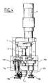
- the tool comprises a body 1 which can be mounted on a spacer 2 of the robot by means of four flexible couplings 3 screwed onto an interface 4 secured to the body.
- a shaft 5 carrying at one of its ends a drive wheel 6 and at its other end a pinion 7 which is engaged with a pinion 8 keyed on the output shaft of a reversible motor 9.
- Two rollers 10 a and 10 b are keyed onto shafts 11 a and 11 b which are rotatably mounted in ears 12 a and 12 b articulated at 13 a and 13 b on the body 1.
- the axes 11 a and 11 b carry toothed wheels 14 a and 14 b which can, by pivoting the ears, come to mesh with a pinion 15 fixed on an axis 16.
- This pinion is engaged with a pinion 17 which is itself engaged with a pinion 18 wedged on the shaft 5.
- the axes of the shaft 5 and of the pinion 17 as well as the axis 16 are located in the median plane AA of the tool.
- Each of the ears 12 a and 12 b is integral with a pin 19 a or 19 b which is engaged in a horizontal slot 20 of a yoke 21 movable vertically.
- This yoke is integral with an axis 22 which is slidably mounted in the body 1 and carries at its end a pair of rollers 23 mounted on the same axis 24.
- This roller is engaged in an oblique slot 25 of a carriage 26 which is slidably mounted relative to the body 1 by means of rollers 27 and is coupled to a jack 28. The operation of this jack causes the carriage 26 to move horizontally which causes the axis 22 and the yoke 21 to move vertically which is linked.
- this yoke rotates the ears 12 a and 12 b , which has the effect of bringing the rollers 10 a and 10 b closer to the median plane AA of the tool or moving it apart of this plane, in the direction of actuation of the jack 28.
- a spatula 29 intended to spread the lip of the joint to be mounted is fixed on the piston rod of a jack 30 fixed on a support 31; an axis 32 slidably mounted in a plate 33, which is fixed to the support 31, limits the sliding movement of the jack rod.
- the support 31 is attached to an axis 34 which is slidably mounted in the body 1 and is integral with a fork 35 coupled to the piston rod of a jack 36.
- a roller 37 mounted madly on the axis 34 and immobilized in translation by a yoke 38 can cooperate with the movable rollers 10 a and 10 b to form a clamp for the door seal to be put in place.
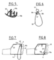
- a ring seal 39 on a door rebate 40 of a motor vehicle.
- a seal has a part 39 a in the form of a clamp and a finishing lip 39 b (Figure 5).
- the joints are initially suspended on the edge of the laying line in a v-shaped device 41 ( Figure 6).
- the roller 10 a or 10 b is used depending on the door in the rebate of which the seal is to be installed. It is assumed below that it is the rebate of the left front door.
- the tool is approached to the joint.
- the jack 28 is brought into the retracted position so that the axis 22 comes in the high position and that the rollers 10 a and 10 b come in the retracted position ( Figure 6).
- the jacks 36 and 30 have been brought in the extended position so that the tip 29 clears the finishing lip 39 b of the seal.
- the caster 37 and the caster 6 come to tangent the outer side of the seal and the roller 10 a passes over the latter.
- the jack 28 is brought into the extended position so that the ears 12 a and 12 b pivot and the roller 10 a presses the seal 39 against the roller 37; at the same time, the toothed wheel 14 a engages with the pinion 15.
- the tool then inserts the seal on the rebate at the intersection of the pavilion 42 and the center leg 43 ( Figure 7). Then the motor 9 is actuated so that the roller 6 constrains the seal in position and completes the installation.
- the rollers 10 a and 10 b are also driven and, as the seal is pinched between the roller 10 a and the roller 37, it is moved longitudinally, which has the effect of both refocusing and pushing it towards the rebate , parallel to it and the roller 6 puts the seal on the rebate.
- the joint is cut up to three quarters, that is to say up to the intersection of the door threshold 44 and the center leg 43 ( Figure 8). At this time, the tool cannot continue on its path because its displacement would have the consequence of removing the part of the joint already laid, the joint being stretched between the roller 10 a and the corner of the pavilion.
- the cylinder 28 is then brought into the retracted position, which releases the seal, the tool is released, the cylinder 28 is again brought into the extended position to bring the rollers 10 a and 10 b towards the median plane of the tool, to prevent them from being a nuisance, and we roll with the roller 6 on the back of the seal 39 from the bottom of the middle foot 43 to the pavilion 42; at this time, the seal is oriented because it is held at the corner of the roof 42 and on the door threshold 44.
- the seal being installed, the tool can proceed with the installation of another seal.
- the cylinder 30 When the joint must cover a cabinet, the cylinder 30 is in the extended position and the cylinder 36 in the retracted position so that the spatula 29 slides on the lip 39 b of the seal, ensuring that this lip correctly covers the cabinet.
- the jack 36 When there is an obstacle during installation, for example a support tab, the jack 36 is brought into the extended position, which releases the spatula.
Landscapes
- Engineering & Computer Science (AREA)
- Mechanical Engineering (AREA)
- Hand Tools For Fitting Together And Separating, Or Other Hand Tools (AREA)
- Automobile Manufacture Line, Endless Track Vehicle, Trailer (AREA)
Claims (7)
- Roboterwerkzeug zum Anbringen einer ringförmigen Dichtung (39) an einem Türfalz eines Kraftfahrzeugs, wobei die Dichtung mit einem zangenförmigen Teil (39a) versehen ist, der dazu geeignet ist, auf den Falz aufgesteckt zu werden, welches eine erste motorisch angetriebene Rolle (6) aufweist, die auf die Außenseite der Zange einwirkt, um sie auf den Falz aufzuziehen, und eine zweite Rolle (10a oder 10b), die an der Innenseite der Zange angreift dadurch gekennzeichnet, daß die zweite Rolle (10a oder 10b) mit einer losen Rolle (37) zusammenwirkt, um die Dichtung oberhalb des Aufziehpunktes zu zentrieren, und ebenfalls motorisch synchron zur ersten Rolle angetrieben ist.
- Werkzeug nach Anspruch 1 dadurch gekennzeichnet, daß es eine dritte motorisch angetriebene Rolle (10b oder 10a) aufweist, die symetrisch zur zweiten Rolle angeordnet und dazu geeignet ist, die gleiche Funktion im Zusammenwirken mit der gleichen losen Rolle (37) in Richtung des Verlaufs des Anbringens auszuüben.
- Werkzeug nach Anspruch 2 dadurch gekennzeichnet, daß die zweite Rolle (10a) und die dritte Rolle (10b) an aufklappbaren Laschen (12a und 12b) angeordnet sind.
- Werkzeug nach Anspruch 3 dadurch gekennzeichnet, daß die Laschen (12a und 12b) schwenkbar am Grundkörper des Werkzeugs angeordnet sind und daß dieser Letztere einen Kolben-Zylinderantrieb (28) zum Verschwenken der Laschen aufweist.
- Werkzeug nach Anspruch 3 oder 4 dadurch gekennzeichnet, daß die Achsen (11a und 11b) der Rollen (10a und 10b) Zahnräder (14a und 14b) tragen, welche durch Verschwenken der Laschen (12a und 12b) in Eingriff mit einem Ritzel (15) kommen können, das in Bezug auf Rotation mit einem auf der Welle der Rolle (6) festgekeilten Ritzel (18) verbunden ist.
- Werkzeug nach einem der Ansprüche 1 bis 5 bestimmt zum Anbringen einer mit einer gehäuseabdeckenden Lippe (39b) versehenen Dichtung (39) gekennzeichnet durch die Tatsache, daß es Mittel (29) aufweist, um die Lippe (39b) während des Aufziehens auf Abstand zu der ersten Rolle (10a) zu bringen.
- Werkzeug nach Anspruch 6 dadurch gekennzeichnet, daß die Mittel zum Aufabstandbringen der Lippe (39b) durch einen Spatel (29) gebildet werden, der an der Kolbenstange eines ersten Kolben-Zylinderantriebs (30) befestigt ist, welcher an einer Achse (34) angeordnet ist, die verschiebbar im Grundkörper (1) des Werkzeugs montiert ist und in axialer Richtung mittels eines zweiten Kolben-Zylinderantriebs (36) verschoben werden kann.
Applications Claiming Priority (2)
| Application Number | Priority Date | Filing Date | Title |
|---|---|---|---|
| FR9004605 | 1990-03-30 | ||
| FR9004605A FR2660226A1 (fr) | 1990-03-30 | 1990-03-30 | Outil de robot pour la pose d'un joint annulaire. |
Publications (2)
| Publication Number | Publication Date |
|---|---|
| EP0449705A1 EP0449705A1 (de) | 1991-10-02 |
| EP0449705B1 true EP0449705B1 (de) | 1993-10-27 |
Family
ID=9395627
Family Applications (1)
| Application Number | Title | Priority Date | Filing Date |
|---|---|---|---|
| EP91400760A Expired - Lifetime EP0449705B1 (de) | 1990-03-30 | 1991-03-21 | Roboterwerkzeug zum Setzen von ringförmigen Profilen |
Country Status (3)
| Country | Link |
|---|---|
| EP (1) | EP0449705B1 (de) |
| DE (1) | DE69100549T2 (de) |
| FR (1) | FR2660226A1 (de) |
Cited By (1)
| Publication number | Priority date | Publication date | Assignee | Title |
|---|---|---|---|---|
| EP2628620A1 (de) | 2012-02-17 | 2013-08-21 | Standard Profil A.S. | Werkzeug zur Montage von Elastomerdichtungen |
Families Citing this family (8)
| Publication number | Priority date | Publication date | Assignee | Title |
|---|---|---|---|---|
| DE19545733A1 (de) * | 1995-12-08 | 1997-06-12 | Saar Gummiwerk Gmbh | SAS - Montageverfahren für Dicht- und Abdeckstreifen sowie Vorrichtung |
| EP0818278A3 (de) * | 1996-07-12 | 2001-08-22 | Standard Products Limited | Vorrichtung zum Crimpen |
| GB2324327B (en) * | 1997-04-18 | 2001-06-13 | Standard Prod Ltd | Clinching tool with rotatable spindles driven by a worm and gear |
| GB2341412B (en) * | 1998-09-11 | 2002-10-30 | Standard Products Co | Mechanism suitable for use in a clinching apparatus and apparatus incorporating such a mechanism |
| DE19904183A1 (de) * | 1999-02-03 | 2000-08-31 | Saar Gummiwerk Gmbh | Vorrichtung zur Montage von Türdichtprofilen nach dem SAS-SGM Verfahren |
| DE10011854C5 (de) * | 2000-03-10 | 2013-06-20 | Fft Edag Produktionssysteme Gmbh & Co. Kg | Rollfalzkopf und Verfahren zum Erzeugen einer Blechfalzverbindung |
| DE10023332B4 (de) * | 2000-05-12 | 2006-09-21 | Daimlerchrysler Ag | Vorrichtung zum Aufbringen eines Kantenschutzprofiles auf die Türöffnung einer Fahrzeugkarosserie |
| DE102007033363C5 (de) * | 2007-06-05 | 2019-04-04 | Tesla Grohmann Automation Gmbh | Verfahren sowie Vorrichtung zum Aufbringen einer Dichtung in Form eines Dichtungsstreifens auf eine Fläche |
Family Cites Families (3)
| Publication number | Priority date | Publication date | Assignee | Title |
|---|---|---|---|---|
| DE3436791A1 (de) * | 1984-10-06 | 1986-04-10 | Messerschmitt-Bölkow-Blohm GmbH, 8012 Ottobrunn | Montagevorrichtung |
| DE3541865A1 (de) * | 1985-11-27 | 1987-06-04 | Volkswagen Ag | Vorrichtung zum automatischen aufstecken eines strangmaterials auf einen flansch |
| US4780943A (en) * | 1986-07-18 | 1988-11-01 | General Motors Corporation | Apparatus and method of a robot for installing weather stripping in a door or like opening |
-
1990
- 1990-03-30 FR FR9004605A patent/FR2660226A1/fr active Granted
-
1991
- 1991-03-21 DE DE91400760T patent/DE69100549T2/de not_active Expired - Fee Related
- 1991-03-21 EP EP91400760A patent/EP0449705B1/de not_active Expired - Lifetime
Cited By (1)
| Publication number | Priority date | Publication date | Assignee | Title |
|---|---|---|---|---|
| EP2628620A1 (de) | 2012-02-17 | 2013-08-21 | Standard Profil A.S. | Werkzeug zur Montage von Elastomerdichtungen |
Also Published As
| Publication number | Publication date |
|---|---|
| DE69100549T2 (de) | 1994-04-28 |
| FR2660226B1 (de) | 1995-04-07 |
| FR2660226A1 (fr) | 1991-10-04 |
| EP0449705A1 (de) | 1991-10-02 |
| DE69100549D1 (de) | 1993-12-02 |
Similar Documents
| Publication | Publication Date | Title |
|---|---|---|
| EP0449705B1 (de) | Roboterwerkzeug zum Setzen von ringförmigen Profilen | |
| EP0559624B1 (de) | Schwenkbetätigungsvorrichtung einer Trittstufenanordnung für Fahrzeuge | |
| EP0115353B1 (de) | Vorrichtung zum Verschieben eines zu bearbeitenden Profils vorbei an Bearbeitungseinrichtungen und in seiner Längsrichtung | |
| EP0387124A1 (de) | Vorrichtung zum automatischen Eindrücken von Dichtungen, insbesondere von einer Dichtung in einer Nut eines Fensters | |
| EP0242309B1 (de) | Biegepresse mit Schwenkbalken | |
| FR2507520A1 (fr) | Pince pour dispositif de levage destine a la manutention de pieces | |
| FR2688849A3 (en) | Drive for the displacement of a moving part of a mechanism | |
| EP0726123B1 (de) | Roboterverbundenes Werkzeug zum Montieren von Dichtungsstreifen | |
| FR2813456A1 (fr) | Dispositif de commande manuelle d'un moteur electrique pour volet roulant | |
| FR2522716A1 (fr) | Porte relevable pliante a deux panneaux | |
| EP1157870B1 (de) | Fensterrollo mit axial beweglicher Zugleiste | |
| EP0662051B1 (de) | Vorrichtung für ein zu öffnendes dach für kraftfahrzeug | |
| CH625355A5 (de) | ||
| FR2606965A1 (fr) | Dispositif de retenue de film pour machine derouleuse et semeuse | |
| FR2644093A1 (fr) | Machine pour la pose automatique de joint souple, en particulier d'un joint exterieur dans une rainure de vantail | |
| EP0022715B1 (de) | Bedienungsvorrichtung zum Öffnen und Schliessen eines Schiebedaches | |
| FR2483269A1 (fr) | Ouvreur de bobine | |
| EP0444988A1 (de) | Automatische Maschine zum Befestigen von Teilen auf Tür- oder Fensterpfosten | |
| WO2006131608A1 (fr) | Dispositif de deplacement de vehicules | |
| FR2660009A1 (fr) | Dispositif de guidage d'une porte coulissante et escamotable de vehicule, et porte coulissante equipee d'un tel dispositif. | |
| FR2783866A1 (fr) | Electro-reducteur pour l'automatisation de volets roulants | |
| FR2531741A1 (fr) | Dispositif pour le positionnement de volets en vue du scellement de leurs gonds | |
| FR2490272A1 (fr) | Dispositif de ripage pour soutenement marchant, en particulier pour soutenement type bouclier ou type pile | |
| JPS5928899Y2 (ja) | スライドル−フ車のル−フ開閉装置 | |
| FR2719332A1 (fr) | Dispositif de motorisation des manÓoeuvres d'ouverture et de fermeture de portes à effacement vertical. |
Legal Events
| Date | Code | Title | Description |
|---|---|---|---|
| PUAI | Public reference made under article 153(3) epc to a published international application that has entered the european phase |
Free format text: ORIGINAL CODE: 0009012 |
|
| AK | Designated contracting states |
Kind code of ref document: A1 Designated state(s): DE GB IT |
|
| 17P | Request for examination filed |
Effective date: 19910812 |
|
| 17Q | First examination report despatched |
Effective date: 19921029 |
|
| GRAA | (expected) grant |
Free format text: ORIGINAL CODE: 0009210 |
|
| AK | Designated contracting states |
Kind code of ref document: B1 Designated state(s): DE GB IT |
|
| REF | Corresponds to: |
Ref document number: 69100549 Country of ref document: DE Date of ref document: 19931202 |
|
| GBT | Gb: translation of ep patent filed (gb section 77(6)(a)/1977) |
Effective date: 19931201 |
|
| ITF | It: translation for a ep patent filed | ||
| PLBE | No opposition filed within time limit |
Free format text: ORIGINAL CODE: 0009261 |
|
| STAA | Information on the status of an ep patent application or granted ep patent |
Free format text: STATUS: NO OPPOSITION FILED WITHIN TIME LIMIT |
|
| 26N | No opposition filed | ||
| PGFP | Annual fee paid to national office [announced via postgrant information from national office to epo] |
Ref country code: GB Payment date: 19950314 Year of fee payment: 5 |
|
| PGFP | Annual fee paid to national office [announced via postgrant information from national office to epo] |
Ref country code: DE Payment date: 19950324 Year of fee payment: 5 |
|
| PG25 | Lapsed in a contracting state [announced via postgrant information from national office to epo] |
Ref country code: GB Effective date: 19960321 |
|
| GBPC | Gb: european patent ceased through non-payment of renewal fee |
Effective date: 19960321 |
|
| PG25 | Lapsed in a contracting state [announced via postgrant information from national office to epo] |
Ref country code: DE Effective date: 19961203 |
|
| PG25 | Lapsed in a contracting state [announced via postgrant information from national office to epo] |
Ref country code: IT Free format text: LAPSE BECAUSE OF NON-PAYMENT OF DUE FEES;WARNING: LAPSES OF ITALIAN PATENTS WITH EFFECTIVE DATE BEFORE 2007 MAY HAVE OCCURRED AT ANY TIME BEFORE 2007. THE CORRECT EFFECTIVE DATE MAY BE DIFFERENT FROM THE ONE RECORDED. Effective date: 20050321 |