EP0449280B1 - Elektromagnetische Kupplung - Google Patents
Elektromagnetische Kupplung Download PDFInfo
- Publication number
- EP0449280B1 EP0449280B1 EP91104932A EP91104932A EP0449280B1 EP 0449280 B1 EP0449280 B1 EP 0449280B1 EP 91104932 A EP91104932 A EP 91104932A EP 91104932 A EP91104932 A EP 91104932A EP 0449280 B1 EP0449280 B1 EP 0449280B1
- Authority
- EP
- European Patent Office
- Prior art keywords
- electromagnetic
- coils
- battery
- electromagnetic device
- signal
- Prior art date
- Legal status (The legal status is an assumption and is not a legal conclusion. Google has not performed a legal analysis and makes no representation as to the accuracy of the status listed.)
- Expired - Lifetime
Links
- 230000033001 locomotion Effects 0.000 claims description 3
- 239000000696 magnetic material Substances 0.000 claims description 3
- 239000003507 refrigerant Substances 0.000 description 18
- 238000004378 air conditioning Methods 0.000 description 10
- 230000000694 effects Effects 0.000 description 4
- 239000002184 metal Substances 0.000 description 4
- 230000005540 biological transmission Effects 0.000 description 3
- 238000010276 construction Methods 0.000 description 3
- 230000009467 reduction Effects 0.000 description 2
- 229910000831 Steel Inorganic materials 0.000 description 1
- 238000001816 cooling Methods 0.000 description 1
- 230000008878 coupling Effects 0.000 description 1
- 238000010168 coupling process Methods 0.000 description 1
- 238000005859 coupling reaction Methods 0.000 description 1
- 230000003247 decreasing effect Effects 0.000 description 1
- 230000007547 defect Effects 0.000 description 1
- 238000010586 diagram Methods 0.000 description 1
- 239000003822 epoxy resin Substances 0.000 description 1
- 230000004907 flux Effects 0.000 description 1
- 238000002844 melting Methods 0.000 description 1
- 230000008018 melting Effects 0.000 description 1
- 230000004048 modification Effects 0.000 description 1
- 238000012986 modification Methods 0.000 description 1
- 230000002093 peripheral effect Effects 0.000 description 1
- 229920000647 polyepoxide Polymers 0.000 description 1
- 230000004044 response Effects 0.000 description 1
- 239000010959 steel Substances 0.000 description 1
Images
Classifications
-
- F—MECHANICAL ENGINEERING; LIGHTING; HEATING; WEAPONS; BLASTING
- F16—ENGINEERING ELEMENTS AND UNITS; GENERAL MEASURES FOR PRODUCING AND MAINTAINING EFFECTIVE FUNCTIONING OF MACHINES OR INSTALLATIONS; THERMAL INSULATION IN GENERAL
- F16D—COUPLINGS FOR TRANSMITTING ROTATION; CLUTCHES; BRAKES
- F16D27/00—Magnetically- or electrically- actuated clutches; Control or electric circuits therefor
- F16D27/10—Magnetically- or electrically- actuated clutches; Control or electric circuits therefor with an electromagnet not rotating with a clutching member, i.e. without collecting rings
- F16D27/108—Magnetically- or electrically- actuated clutches; Control or electric circuits therefor with an electromagnet not rotating with a clutching member, i.e. without collecting rings with axially movable clutching members
- F16D27/112—Magnetically- or electrically- actuated clutches; Control or electric circuits therefor with an electromagnet not rotating with a clutching member, i.e. without collecting rings with axially movable clutching members with flat friction surfaces, e.g. discs
-
- F—MECHANICAL ENGINEERING; LIGHTING; HEATING; WEAPONS; BLASTING
- F16—ENGINEERING ELEMENTS AND UNITS; GENERAL MEASURES FOR PRODUCING AND MAINTAINING EFFECTIVE FUNCTIONING OF MACHINES OR INSTALLATIONS; THERMAL INSULATION IN GENERAL
- F16D—COUPLINGS FOR TRANSMITTING ROTATION; CLUTCHES; BRAKES
- F16D27/00—Magnetically- or electrically- actuated clutches; Control or electric circuits therefor
- F16D27/02—Magnetically- or electrically- actuated clutches; Control or electric circuits therefor with electromagnets incorporated in the clutch, i.e. with collecting rings
-
- F—MECHANICAL ENGINEERING; LIGHTING; HEATING; WEAPONS; BLASTING
- F16—ENGINEERING ELEMENTS AND UNITS; GENERAL MEASURES FOR PRODUCING AND MAINTAINING EFFECTIVE FUNCTIONING OF MACHINES OR INSTALLATIONS; THERMAL INSULATION IN GENERAL
- F16D—COUPLINGS FOR TRANSMITTING ROTATION; CLUTCHES; BRAKES
- F16D48/00—External control of clutches
- F16D48/06—Control by electric or electronic means, e.g. of fluid pressure
- F16D48/064—Control of electrically or electromagnetically actuated clutches
-
- F—MECHANICAL ENGINEERING; LIGHTING; HEATING; WEAPONS; BLASTING
- F16—ENGINEERING ELEMENTS AND UNITS; GENERAL MEASURES FOR PRODUCING AND MAINTAINING EFFECTIVE FUNCTIONING OF MACHINES OR INSTALLATIONS; THERMAL INSULATION IN GENERAL
- F16D—COUPLINGS FOR TRANSMITTING ROTATION; CLUTCHES; BRAKES
- F16D27/00—Magnetically- or electrically- actuated clutches; Control or electric circuits therefor
- F16D2027/002—Electric or electronic circuits relating to actuation of electromagnetic clutches
-
- F—MECHANICAL ENGINEERING; LIGHTING; HEATING; WEAPONS; BLASTING
- F16—ENGINEERING ELEMENTS AND UNITS; GENERAL MEASURES FOR PRODUCING AND MAINTAINING EFFECTIVE FUNCTIONING OF MACHINES OR INSTALLATIONS; THERMAL INSULATION IN GENERAL
- F16D—COUPLINGS FOR TRANSMITTING ROTATION; CLUTCHES; BRAKES
- F16D27/00—Magnetically- or electrically- actuated clutches; Control or electric circuits therefor
- F16D2027/005—Details relating to the internal construction of coils or to clutches having more than one coil in the same housing
-
- F—MECHANICAL ENGINEERING; LIGHTING; HEATING; WEAPONS; BLASTING
- F16—ENGINEERING ELEMENTS AND UNITS; GENERAL MEASURES FOR PRODUCING AND MAINTAINING EFFECTIVE FUNCTIONING OF MACHINES OR INSTALLATIONS; THERMAL INSULATION IN GENERAL
- F16D—COUPLINGS FOR TRANSMITTING ROTATION; CLUTCHES; BRAKES
- F16D2500/00—External control of clutches by electric or electronic means
- F16D2500/10—System to be controlled
- F16D2500/102—Actuator
- F16D2500/1021—Electrical type
- F16D2500/1022—Electromagnet
-
- F—MECHANICAL ENGINEERING; LIGHTING; HEATING; WEAPONS; BLASTING
- F16—ENGINEERING ELEMENTS AND UNITS; GENERAL MEASURES FOR PRODUCING AND MAINTAINING EFFECTIVE FUNCTIONING OF MACHINES OR INSTALLATIONS; THERMAL INSULATION IN GENERAL
- F16D—COUPLINGS FOR TRANSMITTING ROTATION; CLUTCHES; BRAKES
- F16D2500/00—External control of clutches by electric or electronic means
- F16D2500/10—System to be controlled
- F16D2500/104—Clutch
- F16D2500/10443—Clutch type
- F16D2500/10475—Magnetic field, e.g. electro-rheological, magnetisable particles
-
- F—MECHANICAL ENGINEERING; LIGHTING; HEATING; WEAPONS; BLASTING
- F16—ENGINEERING ELEMENTS AND UNITS; GENERAL MEASURES FOR PRODUCING AND MAINTAINING EFFECTIVE FUNCTIONING OF MACHINES OR INSTALLATIONS; THERMAL INSULATION IN GENERAL
- F16D—COUPLINGS FOR TRANSMITTING ROTATION; CLUTCHES; BRAKES
- F16D2500/00—External control of clutches by electric or electronic means
- F16D2500/30—Signal inputs
- F16D2500/302—Signal inputs from the actuator
- F16D2500/3028—Voltage
-
- F—MECHANICAL ENGINEERING; LIGHTING; HEATING; WEAPONS; BLASTING
- F16—ENGINEERING ELEMENTS AND UNITS; GENERAL MEASURES FOR PRODUCING AND MAINTAINING EFFECTIVE FUNCTIONING OF MACHINES OR INSTALLATIONS; THERMAL INSULATION IN GENERAL
- F16D—COUPLINGS FOR TRANSMITTING ROTATION; CLUTCHES; BRAKES
- F16D2500/00—External control of clutches by electric or electronic means
- F16D2500/30—Signal inputs
- F16D2500/304—Signal inputs from the clutch
- F16D2500/30401—On-off signal indicating the engage or disengaged position of the clutch
-
- F—MECHANICAL ENGINEERING; LIGHTING; HEATING; WEAPONS; BLASTING
- F16—ENGINEERING ELEMENTS AND UNITS; GENERAL MEASURES FOR PRODUCING AND MAINTAINING EFFECTIVE FUNCTIONING OF MACHINES OR INSTALLATIONS; THERMAL INSULATION IN GENERAL
- F16D—COUPLINGS FOR TRANSMITTING ROTATION; CLUTCHES; BRAKES
- F16D2500/00—External control of clutches by electric or electronic means
- F16D2500/30—Signal inputs
- F16D2500/304—Signal inputs from the clutch
- F16D2500/30404—Clutch temperature
-
- F—MECHANICAL ENGINEERING; LIGHTING; HEATING; WEAPONS; BLASTING
- F16—ENGINEERING ELEMENTS AND UNITS; GENERAL MEASURES FOR PRODUCING AND MAINTAINING EFFECTIVE FUNCTIONING OF MACHINES OR INSTALLATIONS; THERMAL INSULATION IN GENERAL
- F16D—COUPLINGS FOR TRANSMITTING ROTATION; CLUTCHES; BRAKES
- F16D2500/00—External control of clutches by electric or electronic means
- F16D2500/70—Details about the implementation of the control system
- F16D2500/704—Output parameters from the control unit; Target parameters to be controlled
- F16D2500/70402—Actuator parameters
- F16D2500/7041—Position
Definitions
- This invention relates to an electromagnetic clutch according to the preamble of claim 1, in particular for use in a refrigerant compressor for an automotive air-conditioning system, and more particularly to an electromagnetic clutch that includes an apparatus for interrupting the transmission of the driving force from an automobile engine to the compressor when the compressor becomes locked.
- An automotive air-conditioning system includes a refrigerant circuit comprising a refrigerant compressor, a condenser, an expansion valve and an evaporator , which are connected in series.
- a driving force for driving the compressor is derived from an automobile engine and is transmitted to the compressor through a transmitting device, such as a driving belt which is received by the respective pulleys or rotors associated with the automobile engine and the compressor.
- the rotor associated with the compressor forms a part of an electromagnetic clutch which can intermittently transmit the driving force from the automobile engine to the compressor by virtue of intermittent energization of an electromagnetic coil of the electromagnetic clutch.
- the electromagnetic coil of the clutch intermittently energizes in response to a thermodynamic characteristic of the refrigerant circuit, such as temperature of air leaving from the evaporator.
- the intermittent energization of the electromagnetic coil conducts the intermittent operation of the compressor. Thereby, temperature in a passenger compartment of the automobile can be maintained at a certain value.
- the respective pulleys or rotors associated with the automobile engine and the devices deriving the driving force thereof from the automobile engine receive only one driving belt.
- a driven device of the compressor such as a drive shaft stops its rotational motion due to an unexpected trouble of the component parts of the compressor while the rotor frictionally engages with an armature plate which is directly connected to the drive shaft, a frictional surface of the rotor slides on a frictional surface of the armature plate so that intensive frictional heat is generated therebetween.
- the intensive frictional heat generated between the frictional surfaces of the rotor and the armature plate is conducted to a bearing which rotatably supports the drive shaft, and may cause seizure thereof.
- the seizure of the bearing accelerates the generation of the intensive frictional heat between the frictional surfaces of the rotor and the armature plate.
- the driving belt is not able to endure the intensive frictional heat, and is burntly torn up at last.
- the torn up of the driving belt places the other devices, which derive the driving force thereof from the automobile engine, in an unoperational condition.
- Japanese Utility Model Application Publication No. 57-25222 discloses an electromagnetic clutch including a device which can immediately release the engagement between the rotor and the armature plate when the compressor becomes locked.
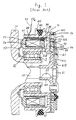
- compressor housing 10 is provided with tubular extension 11 which surrounds drive shaft 20 of the compressor.
- Drive shaft 20 is rotatably supported in compressor housing 10 by a bearing (not shown).
- Rotor 30 is rotatably supported on tubular extension 11 through bearing 12 which is mounted on an outer surface of tubular extension 11.
- Rotor 30 is made of magnetic material, such as steel, and comprises outer annular cylindrical portions 31, inner annular cylindrical portion 32 and axial end plate portion 33 connecting outer and inner cylindrical portion 31, 32 at a right side end. Annular cavity 34 is thus defined between portions 31, 32 and 33.
- An annular V-belt groove 311 is formed on an outer peripheral surface of outer cylindrical portion 31 for receiving V-belt 40 for coupling the compressor to the engine of the automobile (not shown).
- Axial end plate portion 33 has a frictional surface 331 formed on its outer surface and includes one or more concentric slits 332 to define a plurality of annular or arcuate pieces.
- annular housing 51 having a U-shaped cross section is disposed in annular cavity 34 of rotor 30.
- An electromagnetic coil 50 is contained within annular housing 51.
- Housing 51 is fixed to a supporting plate 52, which is secured to an axial end surface of compressor housing 10 by a plurality of rivets (not shown).
- Annular housing 51 is thus maintained within cavity 34 without contacting rotor 30.
- a thermal detecting element 54 including a fusible metal is disposed in a right end portion of annular cavity 510 defined by annular housing 51 so as to be adjacent to axial end plate portion 33 of rotor 30.
- Cavity 510 is filled with heated epoxy resin 511, which is hardened by elapsing time with cooling, so as to fixedly and insulatedly dispose coil 50 and thermal detecting element 54 therewithin.
- Thermal detecting element 54 is connected in series with electromagnetic coil 50 between a battery (not shown) and ground.
- One terminal end of thermal detecting element 54 is connected to the battery, and the other terminal end of thermal detecting element 54 is connected to one terminal end of coil 50.
- the other terminal end of coil 50 is connected to one terminal end of wire 53 which is led from a bottom end portion of annular housing 51.
- the other terminal end 53a of wire 53 is connected to one terminal end of another wire (not shown) led from a control apparatus (not shown) of the automotive air-conditioning system.
- each leaf spring 80 is secured on the outer end surface of armature plate 70 by rivet 73.
- the other end portion of leaf spring 80 is secured on an axial end surface of flange portion 61 of hub 60 by rivet 611 together with stopper plate 90 and washer 612.
- Rotor 30 and armature plate 70 are heated rapidly, and the frictional heat conducting from the frictional surfaces between armature plate 70 and rotor 30 exceeds the melting point of the fusible metal of thermal detecting element 54, the fusible metal will melt. Thereby, the flow of current from the battery to coil 50 is disconnected so that coil 50 is deenergized. Accordingly, armature plate 70 separates from frictional surface 331 of axial end plate portion 33 of rotor 30 by the recoil strength of leaf springs 80. Therefore, rotor 30 idly rotates so that V-belt 40 can be prevented from the torn up. Thus, the function of the other devices which derive the driving force thereof from the automobile engine can be maintained in a normal condition even when the refrigerant compressor becomes locked.
- thermal detecting element 54 is disposed in the right end portion of annular cavity 510 of annular housing 51, the size of coil 50 must be reduced in comparison with the volume of cavity 510, thereby decreasing the magnetic attraction force which acts between rotor 30 and armature plate 70. Furthermore, thermal detecting element 54 may erroneously operate due to the breaking of the fusible metal caused by the intensive vibration which propagates to or is generated at the electromagnetic clutch.
- the electromagnetic clutch of the preamble of claim 1 is known from the US-A-1 671 057.
- the two coils therein are connected in parallel or in series depending on the rotational speed of the clutch.
- It is another object of the present invention is to provide an electromagnetic clutch including a device which can operate to interrupt the transmission of a driving force from an automobile engine to a refrigerant compressor when the refrigerant compressor becomes locked even while the intensive vibration propagates to or is generated at the electromagnetic clutch.
- the electromagnetic clutch according to the invention comprises the features of claim 1.
- Figure 1 illustrates a cross-sectional view of an electromagnetic clutch in accordance with one embodiment of a prior art.
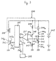
- Figure 3 illustrates a circuit diagram of a control device which controls operation of the electromagnetic clutch shown in Figure 2.
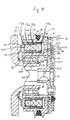
- Figure 4 illustrates a cross-sectional view of an electromagnetic clutch in accordance with a second embodiment of the present invention.
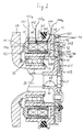
- the electromagnetic clutch according to the first embodiment of the present invention is assembled on a refrigerant compressor which forms a part of an automotive air-conditioning system.
- the electromagnetic clutch includes first and second electromagnetic coils 501 and 502 disposed in cavity 510 of annular housing 51. From the right to the left, first and second coils 501, 502 are disposed in cavity 510 in order, so that first coil 501 is adjacent to axial end plate portion 33 of rotor 30.
- first coil 501 is connected to one terminal end of first wire 100.
- the other terminal end of first coil 501 is connected to one terminal end of second coil 502.
- the other terminal end of second coil 502 is connected to one terminal end of second wire 101.
- control device 200 for controlling operation of the electromagnetic clutch includes comparator 201, judging circuit 202, common-emitter type switching transistor 203 and electromagnetic relay 204 having normally closed contact 204a.
- First and second coils 501 and 502 are connected in series between battery 205 and ground.
- the other terminal end 100a of first wire 100 is connected to battery 205 through normally closed contact 204a.
- the other terminal end 101a of second wire 101 is grounded.
- Resistor 206 and rheostat 207 are connected in series between battery 205 and ground. One terminal end of resistor 206 is connected to battery 205 and one terminal end of rheostat 207 is grounded. One input terminal 201a of comparator 201 is connected to point 208 between resistor 206 and rheostat 207. The other input terminal 201b of comparator 201 is connected the other terminal end 102a of third wire 102, of which one terminal end is connected to point 210 between first and second coils 501, 502. Output terminal 201c of comparator 201 is connected to one input terminal 202a of judging circuit 202.
- the other input terminal 202b of judging circuit 202 is connected to switching device 209 in which an automotive air-conditioning switch (not shown) and a thermistor switch (not shown) are connected in series.
- the thermistor switch is turned on in order to energize coils 501, 502 when temperature of air leaving from an evaporator, which forms a part of the automotive air-conditioning system, exceeds a predetermined value.
- Output terminal 202c of judging circuit 202 is connected to base 203a of transistor 203.
- Collector 203b of transistor 203 is connected to one terminal end of electromagnetic relay 204.
- the other terminal end of electromagnetic relay 204 is connected to one terminal end of resistor 206, thereby being connected to battery 205.
- Voltage Vs at point 208 is adjusted by rheostat 207 to have predetermined value Vs1 which is smaller than voltage Vt at point 210 between first and, second coils 501, 502 at a time when the refrigerant compressor intermittently operates by a predetermined differential.
- Comparator 201 generates level 1 of binary signal Sc only when voltage Vt is smaller than predetermined value Vs1.
- Control device 200 for controlling operation of the electromagnetic clutch performs as follows.
- comparator 201 When the refrigerant compressor intermittently operates, voltage Vt at point 210 at a time both when frictional surface 331 of rotor 30 engages with frictional surface 71 of armature plate 70 and when frictional surface 331 of rotor 30 does not engage with frictional surface 71 of armature plate 70 is greater than predetermined value Vs1. Accordingly, comparator 201 generates level 0 of binary signal Sc, and sends it to judging circuit 202 from output terminal 201c thereof. When level 0 of binary signal Sc is received in judging circuit 202, Judging circuit 202 judges whether switching transistor 203 will be turned on or off with considering whether judging circuit 202 receives ON-signal from switching device 209 or not.
- judging circuit 202 When judging circuit 202 receives ON-signal from switching device 209, that is, when the temperature of air leaving from the evaporator exceeds the predetermined value while the automotive air-conditioning switch is turned on, judging circuit 202 generates level 0 of binary signal Sd, and sends it to base 203a of switching transistor 203 from output terminal 202c thereof.
- base 203a of switching transistor 203 receives level 0 of binary signal Sd
- switching transistor 203 is turned off so that electromagnetic relay 204 is deenergized. Deenergization of electromagnetic relay 204 keeps contact 204a closed so that coils 501, 502 are energized. Accordingly, rotor 30 and armature plate 70 keep the frictional engagement thereof. Therefore, the refrigerant compressor keeps its operation.
- Judging circuit 202 receives OFF-signal from switching device 209, that is, either when the temperature of air leaving from the evaporator does not exceed the predetermined value or when the automotive air-conditioning switch is turned off, judging circuit 202 generates level 1 of binary signal Sd and sends it to base 203a of switching transistor 203 from output terminal 202c thereof.
- base 203a of transistor 203 receives level 1 of binary signal Sd
- switching transistor 203 is turned on so that electromagnetic relay 204 is energized.
- Energization of electromagnetic relay 204 opens contact 204a, thereby deenergizing coils 501, 502. Accordingly, the frictional engagement between rotor 30 and armature plate 70 is released by virtue of the recoil strength of leaf springs 80. Therefore, the refrigerant compressor stops its operation.
- voltage Vt at point 210 between first and second coils 501, 502 is reduced to a value which is smaller than predetermined value Vs1 so that comparator 201 generates level 1 of binary signal Sc, and sends it to judging circuit 202 from output terminal 201c thereof.
- judging circuit 202 judges whether switching transistor 203 will be turned on or off with considering whether judging circuit 202 receives ON-signal from switching device 209 or not.
- judging circuit 202 Even when judging circuit 202 receives ON-signal from switching device 209, that is, when the temperature of air leaving from the evaporator exceeds the predetermined value while the automotive air-conditioning switch is turned on, judging circuit 202 generates level 1 of binary signal Sd, and sends it to base 203a of switching transistor 203 from output terminal 202c thereof.
- base 203a of switching transistor 203 receives level 1 of binary signal Sd
- switching transistor 203 is turned on so that electromagnetic relay 204 is energized.
- Energization of electromagnetic relay 204 opens contact 204a, thereby deenergising coils 501, 502. Accordingly, the frictional engagement between rotor 30 and armature plate 70 is released by virtue of the recoil strength of leaf springs 80. Therefore, rotor 30 idly rotates so that V-belt 40 can be prevented from the torn up. Accordingly, the function of the other devices, which derive the driving force thereof from the engine, can be maintained in
- annular cavity 510 of annular housing 51 is used for disposing only electromagnetic coils 501, 502 therein so that a reduction in the size of coils 501, 502 in comparison with the volume of cavity 510 can be prevented. Therefore, a decrease in the magnetic attraction force acting between rotor 30 and armature plate 70 can be prevented. Furthermore, even though the intensive vibration propagates to or is generated at the electromagnetic clutch, an erroneous operation of control device 200 due to the disconnection caused in control device 200 can be eliminated.
- the electromagnetic clutch includes first, second and third electromagnetic coils 503, 504 and 505 disposed in cavity 510 of annular housing 51. From the right to the left, first, second and third coils 503, 504 and 505 are disposed in cavity 510 in order, so that first coil 503 is adjacent to axial end plate portion 33 of rotor 30.
- One terminal end of first coil 503 is connected to one terminal end of first wire 110.
- the other terminal end of first coil 503 is connected to one terminal end of second coil 504.
- the other terminal end of second coil 504 is connected to one terminal end of third coil 505.
- the other terminal end of third coil 505 is connected to one terminal end of second wire 111.
- first, second and third coils 503, 504 and 505 are connected in series between battery 205 and ground in place of first and second coils 501, 502 of the first embodiment. Therefore, the other terminal end 110a of first wire 110 is connected to battery 205 through normally close contact 204a, and the other terminal end 111a of second wire 111 is grounded. Either a point between first and second coils 503, 504 or a point between second and third coils 504, 505 is connected to one terminal end of third wire 112. The other terminal end 112a of third wire 112 is connected to the other input terminal 201b of comparator 201.
- An effect of this embodiment is similar to an effect of the first embodiment so that an explanation thereof is omitted.
- the other terminal end of the first wire is connected to battery 205 through normally closed contact 204a, and the other terminal end of the second wire is grounded.
- the other terminal end of the second wire can be connected to battery 205 through normally closed contact 204a, and the other terminal end of the first wire can be grounded.
- voltage Vs at point 208 is adjusted by rheostat 207 to have predetermined value Vs2 which is greater than voltage Vt at a point either between the first and second coils or between the second and third coils at a time when the refrigerant compressor intermittently operates by a predetermined differential .
- Comparator 201 generates level 1 of binary signal only when voltage Vt is greater than predetermined value Vs2.
- two or three electromagnetic coils are disposed in cavity 50 of annular housing 51.
- an effect similar to the effect of the above-mentioned embodiments can be obtained by utilizing the thermal differential therebetween as described above.
Landscapes
- Engineering & Computer Science (AREA)
- General Engineering & Computer Science (AREA)
- Physics & Mathematics (AREA)
- Electromagnetism (AREA)
- Mechanical Engineering (AREA)
- Fluid Mechanics (AREA)
- Hydraulic Clutches, Magnetic Clutches, Fluid Clutches, And Fluid Joints (AREA)
- Air-Conditioning For Vehicles (AREA)
- Compressors, Vaccum Pumps And Other Relevant Systems (AREA)
Claims (5)
- Elektromagnetische Kupplung mit einem ersten drehbaren Teil (30) mit einer axialen Endplatte (33) aus magnetischem Material, einem zweiten drehbaren Teil (60), wobei eine Ankerplatte (70) aus magnetischem Material elastisch mit dem zweiten drehbaren Teil so verbunden ist, daß die Ankerplatte (70) zu einer beschränkten axialen Bewegung in der Lage ist, die Ankerplatte (70) der axialen Endplatte (33) des ersten drehbaren Teiles (30) mit einem Luftspalt dazwischen zugewandt ist, und einer elektromagnetischen Einrichtung, die mit dem ersten drehbaren Teil (30) verknüpft ist und betätigbar ist zum Anziehen der Ankerplatte (70) in Kontakt mit der axialen Endplatte derart, daß die Rotation des ersten drehbaren Teiles (30) auf das zweite drehbare Teil (60) durch die Ankerplatte (70) übertragen werden kann, wenn die elektromagnetische Einrichtung aktiviert ist, wobei die elektromagnetische Einrichtung mindestens zwei elektromagnetische Spulen (501, 502; 503, 504, 505) enthält und die mindestens zwei elektromagnetischen Spulen axial miteinander ausgerichtet sind;
dadurch gekennzeichnet, daß eine thermische Differenz zwischen einer und der anderen der mindestens zwei elektromagnetischen Spulen (501, 502; 503, 504, 505) erzeugt wird, wenn Wärme zu der elektromagnetischen Einrichtung von einer Kontaktoberfläche (331, 371) zwischen der axialen Endplatte (33) und der Ankerplatte (75) geleitet wird, wobei die mindestens zwei elektromagnetischen Spulen (501, 502; 503, 504, 505) in Reihe zwischen einer Batterie (205) und Masse geschaltet sind, ein Steuermittel (200) zum Steuern der Verbindung und der Trennung der elektromagnetischen Einrichtung mit/von der Batterie (205) vorgesehen ist, das Steuermittel (200) die elektromagnetische Einrichtung von der Batterie (205) trennt, wenn die thermische Differenz einen vorbestimmten Wert überschreitet, während die elektromagnetische Einrichtung aktiviert ist. - Elektromagnetische Kupplung nach Anspruch 1, bei der das Steuermittel ein Vergleichsmittel (201), ein Beurteilungsmittel (202) und ein Schaltmittel (203, 204, 204a) aufweist, das Vergleichsmittel (201) eine vorbestimmte Spannung mit einer Spannung an einem Punkt zwischen der einen und der anderen elektromagnetischen Spule der mindestens zwei elektromagnetischen Spulen vergleicht, das Vergleichsmittel (201) ein erstes Signal erzeugt, wenn eine Differenz zwischen der vorbestimmten Spannung und der Spannung an dem Punkt zwischen der einen und der anderen elektromagnetischen Spule der mindestens zwei elektromagnetischen Spulen eine vorbestimmte Potentialdifferenz überschreitet, das Beurteilungsmittel (202) ein zweites Signal empfängt, das darstellt, daß entweder die elektromagnetische Einrichtung aktiviert ist oder die elektromagnetische Einrichtung nicht aktiviert ist, das Beurteilungsmittel (202) beurteilt, ob die elektromagnetische Einrichtung von der Batterie getrennt wird oder nicht im Hinblick auf das zweite Signal, das Beurteilungsmittel (202) ein drittes Signal erzeugt, wenn das Beurteilungsmittel das erste Signal empfängt, während das Beurteilungsmittel das zweite Signal empfängt, das darstellt, daß die elektromagnetische Einrichtung aktiviert ist, das Schaltmittel (203, 203, 304a) die elektromagnetische Einrichtung von der Batterie trennt, wenn das Schaltmittel das dritte Signal empfängt.
- Elektromagnetische Kupplung nach Anspruch 2, bei der das Vergleichsmittel einen Komparator aufweist.
- Elektromagnetische Kupplung nach Anspruch 2, bei der das Schaltmittel einen Schalttransistor (203) mit Emitter auf Masse und ein elektromagnetisches Relais (204) mit einem normalerweise geschlossenen Kontakt (204a) aufweist, der zwischen der Batterie (205) und der elektromagnetischen Einrichtung verbunden ist, wobei der Schalttransistor (203) mit Emitter auf Masse und das elektromagnetische Relais (204, 204a) in Reihe zwischen der Batterie (205) und Masse geschaltet sind.
- Elektromagnetische Kupplung nach Anspruch 4, bei der das elektromagnetische Relais (204, 204a) erregt wird, wenn der Schalttransistor (203) mit Emitter auf Masse das dritte Signal empfängt.
Applications Claiming Priority (2)
| Application Number | Priority Date | Filing Date | Title |
|---|---|---|---|
| JP81301/90 | 1990-03-30 | ||
| JP2081301A JP2786302B2 (ja) | 1990-03-30 | 1990-03-30 | 電磁クラッチ |
Publications (2)
| Publication Number | Publication Date |
|---|---|
| EP0449280A1 EP0449280A1 (de) | 1991-10-02 |
| EP0449280B1 true EP0449280B1 (de) | 1994-11-09 |
Family
ID=13742571
Family Applications (1)
| Application Number | Title | Priority Date | Filing Date |
|---|---|---|---|
| EP91104932A Expired - Lifetime EP0449280B1 (de) | 1990-03-30 | 1991-03-27 | Elektromagnetische Kupplung |
Country Status (8)
| Country | Link |
|---|---|
| US (1) | US5295038A (de) |
| EP (1) | EP0449280B1 (de) |
| JP (1) | JP2786302B2 (de) |
| KR (1) | KR100193912B1 (de) |
| CN (1) | CN1029148C (de) |
| AU (1) | AU627403B2 (de) |
| CA (1) | CA2039524C (de) |
| DE (1) | DE69105017T2 (de) |
Families Citing this family (20)
| Publication number | Priority date | Publication date | Assignee | Title |
|---|---|---|---|---|
| US5497870A (en) * | 1994-06-10 | 1996-03-12 | Ogura Clutch Co., Ltd. | Electromagnetic clutch slip protection system |
| JP3627313B2 (ja) * | 1995-03-29 | 2005-03-09 | 株式会社デンソー | 電磁クラッチ |
| JP3837786B2 (ja) * | 1996-09-12 | 2006-10-25 | 株式会社デンソー | 電磁クラッチ |
| JPH10293146A (ja) * | 1997-04-18 | 1998-11-04 | Mitsubishi Electric Corp | インダクタンス変化検出装置 |
| KR100895949B1 (ko) * | 2002-11-14 | 2009-05-07 | 한라공조주식회사 | 압축기용 전자 클러치의 풀리구조 |
| US7325361B2 (en) * | 2003-03-19 | 2008-02-05 | Delphi Technologies, Inc. | Apparatus and method for providing a modular sliding door mechanism |
| US7243461B2 (en) | 2003-03-19 | 2007-07-17 | Rogers Jr Lloyd W | Hinge mechanism for a sliding door |
| US9523231B2 (en) | 2003-11-10 | 2016-12-20 | Strattec Power Access Llc | Attachment assembly and drive unit having same |
| EP1722120A4 (de) * | 2004-03-02 | 2012-10-24 | Ntn Toyo Bearing Co Ltd | Rotationsübertragungsvorrichtung |
| EP1713160B1 (de) * | 2005-04-11 | 2020-06-17 | Delphi Technologies, Inc. | Antriebsvorrichtung für eine motorisch verstellbare Kraftfahrzeugtür mit einem Bewegungsdetektor |
| US7467701B2 (en) * | 2005-05-04 | 2008-12-23 | Visteon Global Technologies, Inc. | Multiple-stage magnetic clutch coil |
| WO2013086461A1 (en) | 2011-12-09 | 2013-06-13 | Metavention, Inc. | Therapeutic neuromodulation of the hepatic system |
| WO2013134543A1 (en) | 2012-03-08 | 2013-09-12 | Medtronic Ardian Luxembourg Sarl | Immune system neuromodulation and associated systems and methods |
| CN102758682B (zh) * | 2012-07-24 | 2015-01-14 | 龙口中宇汽车风扇离合器有限公司 | 电磁风扇离合器 |
| JP6020197B2 (ja) * | 2013-01-24 | 2016-11-02 | アイシン精機株式会社 | ハイブリッド車両のクラッチ制御装置 |
| CN105637249A (zh) * | 2013-10-08 | 2016-06-01 | 三电控股株式会社 | 电磁离合器 |
| US10337216B2 (en) | 2014-01-02 | 2019-07-02 | Strattec Power Access Llc | Vehicle door |
| WO2017168935A1 (ja) * | 2016-03-30 | 2017-10-05 | 日立オートモティブシステムズ株式会社 | 制御回路 |
| CN107800266A (zh) * | 2017-11-01 | 2018-03-13 | 山东洁盟节能环保技术有限公司 | 一种固定磁隙的永磁调速器 |
| CN113002459A (zh) | 2021-03-18 | 2021-06-22 | 精进电动科技股份有限公司 | 混合动力系统中电磁离合器的控制方法和混合动力系统 |
Family Cites Families (11)
| Publication number | Priority date | Publication date | Assignee | Title |
|---|---|---|---|---|
| DE368945C (de) * | 1923-02-12 | Clay Noble | Einrichtung zum Festhalten weicher Vorhemden | |
| US1671057A (en) * | 1923-03-26 | 1928-05-22 | Allis Chalmers Mfg Co | Electromagnetic clutch |
| DE583662C (de) * | 1930-02-15 | 1933-09-07 | Magnet Werk G M B H Eisenach S | Reibungskupplung, deren Reibungsschluss beim Gleiten der Reibflaechen infolge der dabei auftretenden Waermeentwicklung durch eine auf Temperaturerhoehung ansprechende Einrichtung selbsttaetig unterbrochen wird |
| FR1530785A (fr) * | 1967-06-23 | 1968-06-28 | Bendix Corp | Embraage ou frein électromagnétique |
| US4576262A (en) * | 1983-12-27 | 1986-03-18 | Spartanics Ltd. | Method and apparatus for operating a magnetic clutch |
| SE8500520L (sv) * | 1984-02-07 | 1985-08-08 | Baruffaldi Frizioni Spa | Elektromagnetisk koppling |
| US4567975A (en) * | 1984-02-17 | 1986-02-04 | Warner Electric Brake & Clutch Co. | Apparatus and method for controlling the engagement of a gap-type electromagnetic coupling and for alleviating engagement noise |
| US4509091A (en) * | 1984-02-17 | 1985-04-02 | Warner Electric Brake & Clutch Company | Methods and apparatus for controlling the engagement of gap-type electromagnetic couplings |
| USRE33140E (en) * | 1984-02-17 | 1990-01-02 | Dana Corporation | Methods and apparatus for controlling the engagement of gap-type electromagnetic couplings |
| KR940001991B1 (ko) * | 1986-02-03 | 1994-03-12 | 산덴 가부시기가이샤 | 전자기 클러치 |
| DE3816923A1 (de) * | 1987-05-27 | 1988-12-08 | Zahnradfabrik Friedrichshafen | Antrieb fuer ein luefterrad |
-
1990
- 1990-03-30 JP JP2081301A patent/JP2786302B2/ja not_active Expired - Fee Related
-
1991
- 1991-03-27 EP EP91104932A patent/EP0449280B1/de not_active Expired - Lifetime
- 1991-03-27 DE DE69105017T patent/DE69105017T2/de not_active Expired - Fee Related
- 1991-03-28 CN CN91102693A patent/CN1029148C/zh not_active Expired - Lifetime
- 1991-03-28 AU AU73985/91A patent/AU627403B2/en not_active Ceased
- 1991-03-29 KR KR1019910004970A patent/KR100193912B1/ko not_active Expired - Fee Related
- 1991-04-01 US US07/678,246 patent/US5295038A/en not_active Expired - Fee Related
- 1991-04-02 CA CA002039524A patent/CA2039524C/en not_active Expired - Fee Related
Also Published As
| Publication number | Publication date |
|---|---|
| EP0449280A1 (de) | 1991-10-02 |
| JPH03282020A (ja) | 1991-12-12 |
| CA2039524C (en) | 1997-01-21 |
| CA2039524A1 (en) | 1991-10-01 |
| KR100193912B1 (ko) | 1999-06-15 |
| KR910017095A (ko) | 1991-11-05 |
| AU627403B2 (en) | 1992-08-20 |
| US5295038A (en) | 1994-03-15 |
| AU7398591A (en) | 1991-10-03 |
| JP2786302B2 (ja) | 1998-08-13 |
| CN1057707A (zh) | 1992-01-08 |
| CN1029148C (zh) | 1995-06-28 |
| DE69105017T2 (de) | 1995-05-18 |
| DE69105017D1 (de) | 1994-12-15 |
Similar Documents
| Publication | Publication Date | Title |
|---|---|---|
| EP0449280B1 (de) | Elektromagnetische Kupplung | |
| US4799578A (en) | Apparatus for preventing heat damage in an electromagnetic clutch | |
| US5443372A (en) | Coupling mechanism for a compressor | |
| EP0254295A1 (de) | Kupplungseinrichtung für einen Kompressor | |
| US6209699B1 (en) | Electromagnetic clutch | |
| US9709105B2 (en) | Clutch mechanism | |
| US20120175978A1 (en) | Air-cooled electrical machine | |
| US4376476A (en) | Driving circuit for magnetic clutches for use with refrigerant compressors | |
| US7017726B2 (en) | Electromagnetic clutch | |
| US6169347B1 (en) | Rotating coil electromagnetic clutch | |
| US6161671A (en) | Electromagnetic clutch | |
| US5404980A (en) | Electromagnetic clutch with failure protection apparatus | |
| US6019693A (en) | Method for mounting two auxiliary machines to automobile and power transmission device | |
| US5601176A (en) | Armature assembly in an electromagnetic coupling device | |
| KR100506166B1 (ko) | 전자클러치 | |
| US7367439B2 (en) | Electromagnetic clutch with elastic member easily melted | |
| US20020001533A1 (en) | Gas Compressor and air conditioning system | |
| JPH07286632A (ja) | 電磁クラッチ及びデファレンシャル装置 | |
| JP2576515B2 (ja) | 圧縮機駆動用電磁クラッチの制御装置 | |
| JP2000230579A (ja) | 電磁クラッチ | |
| JPH06109031A (ja) | 電磁クラッチ | |
| KR100658989B1 (ko) | 압축기의전자클러치 | |
| KR100490590B1 (ko) | 압축기의전자클러치 | |
| KR200162259Y1 (ko) | 압축기의 전자클러치 온도감지장치 | |
| KR19990057641A (ko) | 전자클러치 |
Legal Events
| Date | Code | Title | Description |
|---|---|---|---|
| PUAI | Public reference made under article 153(3) epc to a published international application that has entered the european phase |
Free format text: ORIGINAL CODE: 0009012 |
|
| AK | Designated contracting states |
Kind code of ref document: A1 Designated state(s): DE FR GB IT SE |
|
| 17P | Request for examination filed |
Effective date: 19920330 |
|
| 17Q | First examination report despatched |
Effective date: 19930820 |
|
| GRAA | (expected) grant |
Free format text: ORIGINAL CODE: 0009210 |
|
| AK | Designated contracting states |
Kind code of ref document: B1 Designated state(s): DE FR GB IT SE |
|
| ITF | It: translation for a ep patent filed | ||
| REF | Corresponds to: |
Ref document number: 69105017 Country of ref document: DE Date of ref document: 19941215 |
|
| ET | Fr: translation filed | ||
| EAL | Se: european patent in force in sweden |
Ref document number: 91104932.8 |
|
| PLBE | No opposition filed within time limit |
Free format text: ORIGINAL CODE: 0009261 |
|
| STAA | Information on the status of an ep patent application or granted ep patent |
Free format text: STATUS: NO OPPOSITION FILED WITHIN TIME LIMIT |
|
| 26N | No opposition filed | ||
| PGFP | Annual fee paid to national office [announced via postgrant information from national office to epo] |
Ref country code: SE Payment date: 20010306 Year of fee payment: 11 |
|
| PGFP | Annual fee paid to national office [announced via postgrant information from national office to epo] |
Ref country code: FR Payment date: 20010313 Year of fee payment: 11 |
|
| PGFP | Annual fee paid to national office [announced via postgrant information from national office to epo] |
Ref country code: DE Payment date: 20010319 Year of fee payment: 11 |
|
| PGFP | Annual fee paid to national office [announced via postgrant information from national office to epo] |
Ref country code: GB Payment date: 20010321 Year of fee payment: 11 |
|
| REG | Reference to a national code |
Ref country code: GB Ref legal event code: IF02 |
|
| PG25 | Lapsed in a contracting state [announced via postgrant information from national office to epo] |
Ref country code: GB Free format text: LAPSE BECAUSE OF NON-PAYMENT OF DUE FEES Effective date: 20020327 |
|
| PG25 | Lapsed in a contracting state [announced via postgrant information from national office to epo] |
Ref country code: SE Free format text: LAPSE BECAUSE OF NON-PAYMENT OF DUE FEES Effective date: 20020328 |
|
| PG25 | Lapsed in a contracting state [announced via postgrant information from national office to epo] |
Ref country code: DE Free format text: LAPSE BECAUSE OF NON-PAYMENT OF DUE FEES Effective date: 20021001 |
|
| EUG | Se: european patent has lapsed |
Ref document number: 91104932.8 |
|
| GBPC | Gb: european patent ceased through non-payment of renewal fee |
Effective date: 20020327 |
|
| PG25 | Lapsed in a contracting state [announced via postgrant information from national office to epo] |
Ref country code: FR Free format text: LAPSE BECAUSE OF NON-PAYMENT OF DUE FEES Effective date: 20021129 |
|
| REG | Reference to a national code |
Ref country code: FR Ref legal event code: ST |
|
| PG25 | Lapsed in a contracting state [announced via postgrant information from national office to epo] |
Ref country code: IT Free format text: LAPSE BECAUSE OF NON-PAYMENT OF DUE FEES;WARNING: LAPSES OF ITALIAN PATENTS WITH EFFECTIVE DATE BEFORE 2007 MAY HAVE OCCURRED AT ANY TIME BEFORE 2007. THE CORRECT EFFECTIVE DATE MAY BE DIFFERENT FROM THE ONE RECORDED. Effective date: 20050327 |