EP0448931B1 - Procédé pour mesurer un spécimen sous utilisation de lumière fluorescente - Google Patents
Procédé pour mesurer un spécimen sous utilisation de lumière fluorescente Download PDFInfo
- Publication number
- EP0448931B1 EP0448931B1 EP91100755A EP91100755A EP0448931B1 EP 0448931 B1 EP0448931 B1 EP 0448931B1 EP 91100755 A EP91100755 A EP 91100755A EP 91100755 A EP91100755 A EP 91100755A EP 0448931 B1 EP0448931 B1 EP 0448931B1
- Authority
- EP
- European Patent Office
- Prior art keywords
- light
- fluorescence
- specimen
- fluorescence light
- time
- Prior art date
- Legal status (The legal status is an assumption and is not a legal conclusion. Google has not performed a legal analysis and makes no representation as to the accuracy of the status listed.)
- Expired - Lifetime
Links
Images


Classifications
-
- G—PHYSICS
- G01—MEASURING; TESTING
- G01N—INVESTIGATING OR ANALYSING MATERIALS BY DETERMINING THEIR CHEMICAL OR PHYSICAL PROPERTIES
- G01N21/00—Investigating or analysing materials by the use of optical means, i.e. using sub-millimetre waves, infrared, visible or ultraviolet light
- G01N21/62—Systems in which the material investigated is excited whereby it emits light or causes a change in wavelength of the incident light
- G01N21/63—Systems in which the material investigated is excited whereby it emits light or causes a change in wavelength of the incident light optically excited
- G01N21/64—Fluorescence; Phosphorescence
- G01N21/645—Specially adapted constructive features of fluorimeters
-
- G—PHYSICS
- G01—MEASURING; TESTING
- G01N—INVESTIGATING OR ANALYSING MATERIALS BY DETERMINING THEIR CHEMICAL OR PHYSICAL PROPERTIES
- G01N15/00—Investigating characteristics of particles; Investigating permeability, pore-volume, or surface-area of porous materials
- G01N15/10—Investigating individual particles
- G01N15/14—Electro-optical investigation, e.g. flow cytometers
-
- G—PHYSICS
- G01—MEASURING; TESTING
- G01N—INVESTIGATING OR ANALYSING MATERIALS BY DETERMINING THEIR CHEMICAL OR PHYSICAL PROPERTIES
- G01N21/00—Investigating or analysing materials by the use of optical means, i.e. using sub-millimetre waves, infrared, visible or ultraviolet light
- G01N21/62—Systems in which the material investigated is excited whereby it emits light or causes a change in wavelength of the incident light
- G01N21/63—Systems in which the material investigated is excited whereby it emits light or causes a change in wavelength of the incident light optically excited
- G01N21/64—Fluorescence; Phosphorescence
- G01N21/6428—Measuring fluorescence of fluorescent products of reactions or of fluorochrome labelled reactive substances, e.g. measuring quenching effects, using measuring "optrodes"
-
- G—PHYSICS
- G01—MEASURING; TESTING
- G01N—INVESTIGATING OR ANALYSING MATERIALS BY DETERMINING THEIR CHEMICAL OR PHYSICAL PROPERTIES
- G01N15/00—Investigating characteristics of particles; Investigating permeability, pore-volume, or surface-area of porous materials
- G01N15/10—Investigating individual particles
- G01N15/14—Electro-optical investigation, e.g. flow cytometers
- G01N15/1456—Electro-optical investigation, e.g. flow cytometers without spatial resolution of the texture or inner structure of the particle, e.g. processing of pulse signals
- G01N15/1459—Electro-optical investigation, e.g. flow cytometers without spatial resolution of the texture or inner structure of the particle, e.g. processing of pulse signals the analysis being performed on a sample stream
-
- G—PHYSICS
- G01—MEASURING; TESTING
- G01N—INVESTIGATING OR ANALYSING MATERIALS BY DETERMINING THEIR CHEMICAL OR PHYSICAL PROPERTIES
- G01N21/00—Investigating or analysing materials by the use of optical means, i.e. using sub-millimetre waves, infrared, visible or ultraviolet light
- G01N21/62—Systems in which the material investigated is excited whereby it emits light or causes a change in wavelength of the incident light
- G01N21/63—Systems in which the material investigated is excited whereby it emits light or causes a change in wavelength of the incident light optically excited
- G01N21/64—Fluorescence; Phosphorescence
- G01N21/6408—Fluorescence; Phosphorescence with measurement of decay time, time resolved fluorescence
- G01N2021/641—Phosphorimetry, gated
-
- G—PHYSICS
- G01—MEASURING; TESTING
- G01N—INVESTIGATING OR ANALYSING MATERIALS BY DETERMINING THEIR CHEMICAL OR PHYSICAL PROPERTIES
- G01N21/00—Investigating or analysing materials by the use of optical means, i.e. using sub-millimetre waves, infrared, visible or ultraviolet light
- G01N21/62—Systems in which the material investigated is excited whereby it emits light or causes a change in wavelength of the incident light
- G01N21/63—Systems in which the material investigated is excited whereby it emits light or causes a change in wavelength of the incident light optically excited
- G01N21/64—Fluorescence; Phosphorescence
- G01N21/6428—Measuring fluorescence of fluorescent products of reactions or of fluorochrome labelled reactive substances, e.g. measuring quenching effects, using measuring "optrodes"
- G01N2021/6439—Measuring fluorescence of fluorescent products of reactions or of fluorochrome labelled reactive substances, e.g. measuring quenching effects, using measuring "optrodes" with indicators, stains, dyes, tags, labels, marks
-
- Y—GENERAL TAGGING OF NEW TECHNOLOGICAL DEVELOPMENTS; GENERAL TAGGING OF CROSS-SECTIONAL TECHNOLOGIES SPANNING OVER SEVERAL SECTIONS OF THE IPC; TECHNICAL SUBJECTS COVERED BY FORMER USPC CROSS-REFERENCE ART COLLECTIONS [XRACs] AND DIGESTS
- Y10—TECHNICAL SUBJECTS COVERED BY FORMER USPC
- Y10S—TECHNICAL SUBJECTS COVERED BY FORMER USPC CROSS-REFERENCE ART COLLECTIONS [XRACs] AND DIGESTS
- Y10S435/00—Chemistry: molecular biology and microbiology
- Y10S435/808—Optical sensing apparatus
-
- Y—GENERAL TAGGING OF NEW TECHNOLOGICAL DEVELOPMENTS; GENERAL TAGGING OF CROSS-SECTIONAL TECHNOLOGIES SPANNING OVER SEVERAL SECTIONS OF THE IPC; TECHNICAL SUBJECTS COVERED BY FORMER USPC CROSS-REFERENCE ART COLLECTIONS [XRACs] AND DIGESTS
- Y10—TECHNICAL SUBJECTS COVERED BY FORMER USPC
- Y10S—TECHNICAL SUBJECTS COVERED BY FORMER USPC CROSS-REFERENCE ART COLLECTIONS [XRACs] AND DIGESTS
- Y10S435/00—Chemistry: molecular biology and microbiology
- Y10S435/968—High energy substrates, e.g. fluorescent, chemiluminescent, radioactive
-
- Y—GENERAL TAGGING OF NEW TECHNOLOGICAL DEVELOPMENTS; GENERAL TAGGING OF CROSS-SECTIONAL TECHNOLOGIES SPANNING OVER SEVERAL SECTIONS OF THE IPC; TECHNICAL SUBJECTS COVERED BY FORMER USPC CROSS-REFERENCE ART COLLECTIONS [XRACs] AND DIGESTS
- Y10—TECHNICAL SUBJECTS COVERED BY FORMER USPC
- Y10S—TECHNICAL SUBJECTS COVERED BY FORMER USPC CROSS-REFERENCE ART COLLECTIONS [XRACs] AND DIGESTS
- Y10S436/00—Chemistry: analytical and immunological testing
- Y10S436/80—Fluorescent dyes, e.g. rhodamine
-
- Y—GENERAL TAGGING OF NEW TECHNOLOGICAL DEVELOPMENTS; GENERAL TAGGING OF CROSS-SECTIONAL TECHNOLOGIES SPANNING OVER SEVERAL SECTIONS OF THE IPC; TECHNICAL SUBJECTS COVERED BY FORMER USPC CROSS-REFERENCE ART COLLECTIONS [XRACs] AND DIGESTS
- Y10—TECHNICAL SUBJECTS COVERED BY FORMER USPC
- Y10S—TECHNICAL SUBJECTS COVERED BY FORMER USPC CROSS-REFERENCE ART COLLECTIONS [XRACs] AND DIGESTS
- Y10S436/00—Chemistry: analytical and immunological testing
- Y10S436/805—Optical property
Definitions
- This invention relates to a method wherein light is applied to individual specimens and scattered lights and fluorescence light created thereby are optically detected to thereby accomplish measurement of the specimens.
- a flow cytometer is known as an example of the prior-art specimen examining apparatus. This is such that specimens in blood corpuscle cells or the like in sample liquid are fluorescence-dyed and these specimens are caused to flow one by one to an examined portion to which a light beam is applied and as a result, scattered lights, fluorescence light, etc. created from the individual specimens passing through the examined portion are wavelength-sorted and metered, whereby the analysis of the specimens is effected from the statistical tendency of measurement parameters regarding a number of specimens. Thereby, the DNA analysis of cells, the search of surface antigen, etc. become possible.
- pulse light is applied to a sample fixed on a support in order to detect reflected light of said pulse light by a photo tube, wherein based on the timing of said reflected light delay fluorescence light is detected by a detector.
- pulse light also is irradiated onto a fixed sample, and delay fluorescence light is detected based on the timing thereof at a predetermined time.
- pulse light is irradiated onto a fixed example in order to detect fluorescence light from all of the particles in the sample.
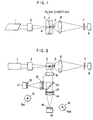
- Figures 1 and 2 show the construction of an apparatus according to a first embodiment of the present invention.
- Figure 3 is a block diagram of the signal processing unit of the apparatus according to the first embodiment.
- Figure 4 is a graph of the life curve of fluorescence light.
- Figure 5 shows the relation between the shape of an aperture and measurement time.
- Figure 6 shows the construction of an apparatus according to a second embodiment of the present invention.
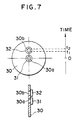
- Figure 7 shows the construction of an aperture in the second embodiment.
- Figure 1 shows an optical arrangement when the apparatus of an embodiment is seen from a side thereof
- Figure 2 shows the optical arrangement when the apparatus is seen from above it.
- Sample liquid such as a blood sample or carrier particle suspended liquid in which minute specimens are suspended is prepared, and this sample liquid is dye-treated as a pre-treatment by a fluorescent reagent and regulated into an appropriate reaction time and concentration.
- sheath liquid such as physiological saline solution or distilled water is prepared. Then, these liquids are pressurized by a pressurizing mechanism, not shown, and are directed to a flow cell 3, and a fine stream of sample liquid is formed in such a manner as to wrap the sample liquid in the sheath liquid by the sheath flow principle.
- specimens contained in the sample liquid i.e., minute particles such as individual cells and latices are separated from one another and successively flow one by one from above to below as viewed in the plane of the drawing sheet.
- Laser light emitted from a laser source 1 (in the present embodiment, ultraviolet laser of wavelength 300 nm) is applied to the flow of these particles while being converged into any elliptical shape by an imaging optical system 2 having two cylindrical lenses whose bus bar directions are a flow-through portion direction and orthogonal to the flow-through portion direction, respectively.
- the shape of the light beam applied to the particles may generally be an elliptical shape having its major diameter in a direction orthogonal to the flow. This is for the purpose of causing the light beam to be applied to the particles with uniform intensity even if the position of the flow of the individual particles somewhat fluctuates in the fluid.
- the forwardly scattered light created in the forward direction is metered by a condensing lens 6, an aperture 7 and a photodetector 8.
- the opening portion of the aperture 7 is disposed conjugately with a light applying position 4 so that only the light from the light applying position 4 may be directed to the photodetector 8.
- a minute stopper 5 of light absorbing property is disposed short of the condensing lens 6 in the optical path, whereby there is constructed a dark field optical system so that the direct light from the light source and light transmitted through the particles may be removed.
- the intensity of light including the fluorescence light as well as the forwardly scattered light is metered, but there is no problem because the intensity of the fluorescence light is generally very weak as compared with the intensity of the forwardly scattered light.
- a band-pass filter for selectively transmitting the scattered light wavelengths therethrough may be disposed short of the photodetector 8.
- the light created in a sideways direction orthogonal to the optic axis of the laser and to the flow of the particles is condensed by the condensing lens 9 as shown in Figure 2.
- the condensed light has its wavelength component of the set wavelength or below reflected by a dichroic mirror 10, and via a band-pass filter 11 for selectively transmitting the wavelengths of the scattered lights, i.e., the wavelength of the laser light (in the vicinity of 300 nm) therethrough, a condensing lens 13 and an aperture 15, the sideways scattered light is metered by a photodetector 17.
- the aperature 15 has its opening portion 15a provided at the center of the optic axis as shown, and the opening portion 15a is in conjugate relationship with the light applying position 4 so that only the scattered light created from the light applying position 4 may be detected by the photodetector 17.
- the fluorescence light condensed by the condensing lens 9 and passed through the dichroic mirror 10 is wavelength-selected by a band-pass filter 12 for fluorescence wavelength, and fluorescence light of a particular wavelength is detected by the set of a condensing lens 14, an aperture 16 and a photodetector 18.
- the aperture 16 has its opening portion 16a provided somewhat above the center thereof, as shown. That is, the opening portion 16a is conjugate with a position somewhat downstream of the light applying position so as to direct only the fluorescence light of the particular wavelength from a non-applying position downstream of the light applying position 4 to the photodetector 18.
- the light does not enter the photodetector 17 for metering the scattered light and the photodetector 18 for metering the fluorescence light, at a time, and the scattered light is detected during an application period and the fluorescence light is detected during the non-application period so that the output pulse of each photodetector may be time-serially obtained.
- the signals of the photodetectors 8, 17 and 18 are processed by a signal processing circuit as shown in Figure 3.
- the forwardly scattered light output of the photodetector 8 is input as a pulse-like electrical signal to a trigger circuit 21 and an analogue processing circuit 22.
- the sideways scattered light output of the photodetector 17 and the fluorescence light output of the photodetector 18 are input to analogue processing circuits 23 and 24, respectively.
- the peak values and integrated values of the signal pulses are detected.
- a trigger signal is produced in response thereto for a predetermined period, and that signal is input to the analogue processing circuits 22 and 23.
- Each analogue processing circuit has the sampling and holding function so that the input signal may be processed only for the period during which a trigger signal is produced.
- the trigger signal from the trigger circuit 21 is input to a trigger generating circuit 25 for fluorescence light, and this trigger generating circuit 25 for fluorescence light generates a trigger signal for a time t1 to a time t2, and that signal is input to the analogue processing circuit 24.
- the signal of the photodetector 18 for fluorescence light can be sampled for the time t1 to the time t2 after the particle has passed through the light applying position 4.
- the outputs of the analogue processing circuits 22, 23 and 24 are converted into digital values by an A/D converting circuit 26, and are stored into a memory 27 as a forwardly scattered light signal, a sideways scattered light signal and a fluorescence light signal, respectively.
- the calculation of specimen analysis is effected in a calculation circuit 28, and the result of the calculation is output to an output unit 29 such as a CRT or a printer.
- the fluorescence dye used here is one whose fluorescence life is longer than that of ordinary self-fluorescence light or the like.
- Figure 4 shows a graph of the life curve of fluorescence light excited by light application.
- the abscissa represents lapse time, and the moment at which light is applied to the particles in the examined portion and the application of the light has been finished is a time 0.
- the ordinate represents the intensity of fluorescence light created.
- curve 19 indicates the life curve by usually used fluorescence dye or self-fluorescence light possessed by cells or dust, and the life of fluorescence light from after it is excited until fluorescence light generation intensity becomes zero is about 100 nsec.
- curve 20 is the life curve of the fluorescence dye having a longer life than usual which is used in the present embodiment, and for example, Eu3+ chelate substance has been used as the fluorescence dye.
- the life of fluorescence light in this case is 1000 nsec. or longer.
- This fluorescence light life curve has its peak output determined in conformity with the quantity of the fluorescence light coloring matter if the intensity of the laser light which excites fluorescence light is constant.
- the opening portion 16a of the aperture 16 shown in Figure 5 is disposed conjugately with the non-applying position somewhat downstream of the light applying position to which a light spot is applied so that only the light from this portion may be directed to the photodetector 18. In other words, considering that the flow speed of the particles is constant, only the light in the hatched portion from the time t1 to the time t2 of Figure 4 is metered.
- the intensity of fluorescence light metered during the time t1 to t2 is partial one which does not include the peak value, but this poses no problem because there is obtained a value substantially proportional to the peak output conforming to the quantity of the fluorescence dye.
- a correction coefficient can be provided to the light metering output on the basis of the shape of this curve and the times t1 and t2 to thereby estimate the peak value or the integrated value.
- the measured value once memorized in the memory 27 is later corrected by a calculation process to thereby estimate the peak value or the integrated value.
- Eu3+ chelate has a property of being excited by a wavelength in the vicinity of 300 nm and creating fluorescence light of a wavelength in the vicinity of 610 nm for a long time.
- this reagent is mixed with a blood sample diluted to a moderate concentration and is reacted with the latter for a predetermined time, thereby accomplishing cell dyeing.
- Figure 6 shows the construction of the optical system of the second embodiment and corresponds to Figure 2.
- reference characters identical to those in Figure 2 designate identical or equivalent members.
- Figure 7 shows the details of an aperture 30.
- the band-pass filter 12 in Figure 2 which shows the previous embodiment is omitted and an aperture 30 having a plurality of opening portions is disposed in place of the aperture 16.
- the detailed construction of the aperture 30 is as shown in Figure 7.
- two opening portions 30a and 30b are provided at and near the central portion of the light-intercepting aperture 30.
- Band-pass filters 31 and 32 are attached to the opening portions 30a and 30b, respectively, and each of these band-pass filters has a property of selectively transmitting fluorescent light of a particular wavelength therethrough.
- the opening portion 30a is provided at the central portion of the aperture 30, and the opening portion 30b is provided somewhat above it.
- the opening portion 30a is conjugate with the light applying position 4, and the opening portion 30b is conjugate with a position somewhat downstream of the light applying position 4. That is, fluorescence light of a particular wavelength emitted from the light applying position 4 is selectively directed to the photodetector 18 by the opening portion 30a, and only fluorescence light of a particular wavelength from the non-applying position downstream of the light applying position 4 is directed to the photodetector 18 by the opening portion 30b. That is, design is made such that the light metering output pulses of two kinds of fluorescence lights are time-serially obtained in the photodetector 18, and two kinds of fluorescence light parameters are time-serially obtained in one and the same photodetector.
- a light source having a wide wavelength range such as a multi-oscillation laser source may be adopted or a plurality of light beams differing in wavelength from one another may be optically combined to thereby make a single light beam.
- band-pass filters having the characteristics of selectively transmitting said first and second fluorescence lights therethrough are selected as the band-pass filters 31 and 32 of the aperture 30.
- the first and second fluorescence lights selectively and time-serially enter the photodetector 18, and two different fluorescence lights can be measured by a single photodetector.
- the second fluorescence light of a long light emission life is measured in the time range t1-t2 wherein the first fluorescence light is not created and therefore, very accurate measured values can be obtained without being subjected to the mixing of miscellaneous light.
- the number of openings in the aperture 30 is not limited to two, but a plurality of openings are provided conjugately with a plurality of non-applying positions along the flow of the particles, still more parameters can be obtained time-serially.
- plural kinds of fluorescence lights having a long fluorescence life are prepared and the particles are dyed with these at a time. Then, these fluorescence lights are wavelength-selected by band-pass filters formed on the respective opening portions and individually detected, whereby the intensities of the fluorescence lights of a plurality of parameters free of the influence of miscellaneous light can be obtained time-serially by one measurement.
- the characteristic of the band-pass filter 31 is made such as to selectively transmit the wavelengths of scattered lights therethrough, the two different parameters of the sideways scattered light and fluorescent light can be obtained by one and the same photodetector 18.
- the scattered light and fluorescence light have a great intensity difference there been and therefore, it is preferable to use a photodetector 18 of a wide dynamic range or use a band-pass filter 31 having a high degree of light attenuation.
- the intensity of fluorescence light measured by the utilization of the delay of time is entirely free of the influence of miscellaneous light and highly accurate and further, more kinds of measured parameters than the number of the photodetectors can be obtained, and this contributes to the compactness and reduced cost of the apparatus.
- first and second monoclonal antibodies uniquely coupling to first and second surface antigens, respectively, on the surface of a cell which is a specimen are first prepared. Further, two kinds of fluorescence dyes, i.e., a first fluorescence dye and a second fluorescence dye having a longer fluorescence life than the first fluorescence dye are prepared. The first fluorescence dye is then labelled on the first monoclonal antibody by a process similar to that previously described, and the second fluorescence dye is likewise labelled on the second monoclonal antibody. These are mixed together, whereby there can be obtained a reagent for examining two kinds of surface antigens at a time.
- fluorescence dyes i.e., a first fluorescence dye and a second fluorescence dye having a longer fluorescence life than the first fluorescence dye are prepared.
- the first fluorescence dye is then labelled on the first monoclonal antibody by a process similar to that previously described, and the second fluorescence dye is likewise
- This reagent is then mixed with a blood sample diluted to moderate concentration and is reacted with the latter for a predetermined time, and each monoclonal antibody is coupled to a desired antibody on the surface of the cell, whereby the fluorescence dyeing of the cell is substantially effected through the monoclonal antibodies.
- This reacted sample liquid is measured by the above-described apparatus, and fluorescence lights of two colors are time-serially measured. When the first fluorescence light is detected, the presence of the first surface antigen can be confirmed, and when the second fluorescence light is detected, the presence of the second surface antigen can be confirmed.
- the quantity of the surface antigens can also be estimated from the intensity of the fluorescence lights. In this manner, the qualitative or quantitative measurements of two kinds of surface antigens can be accomplished at a time by one measurement.
Landscapes
- Health & Medical Sciences (AREA)
- Chemical & Material Sciences (AREA)
- Immunology (AREA)
- Physics & Mathematics (AREA)
- General Health & Medical Sciences (AREA)
- Pathology (AREA)
- General Physics & Mathematics (AREA)
- Life Sciences & Earth Sciences (AREA)
- Analytical Chemistry (AREA)
- Biochemistry (AREA)
- Nuclear Medicine, Radiotherapy & Molecular Imaging (AREA)
- Optics & Photonics (AREA)
- Chemical Kinetics & Catalysis (AREA)
- Dispersion Chemistry (AREA)
- Investigating, Analyzing Materials By Fluorescence Or Luminescence (AREA)
Claims (6)
- Procédé de mesure d'échantillons, comprenant les étapes dans lesquelles :- on irradie un échantillon comprenant des particules, colorées avec un colorant fluorescent, avec de la lumière dans une position prédéterminée ;- on détecte une lumière dispersée provenant de l'échantillon dans la position prédéterminée ; et- on détecte une lumière fluorescente provenant dudit échantillon,caractérisé par les étapes dans lesquelleson fait passer lesdites particules de l'échantillon une par une par la position prédéterminée, eton détecte la lumière fluorescente provenant de chacune desdites particules dans une position en aval de la position prédéterminée qui n'est pas irradiée par la lumière.
- Procédé selon la revendication 1, caractérisé par l'étape dans laquelle :
on établit une période pour détecter la lumière fluorescente sur la base d'un temps de détection de ladite lumière dispersée. - Procédé selon la revendication 1 ou 2, caractérisé par l'étape dans laquelle :
on corrige l'intensité de la lumière fluorescente détectée pour déterminer une valeur de crête estimée de ladite lumière fluorescente par calcul d'un coefficient de correction sur la base de la courbe de durée de vie de la lumière fluorescente. - Procédé selon l'une des revendications 1 à 3, caractérisé en ce que l'échantillon est coloré avec le colorant fluorescent par l'utilisation d'un anticorps.
- Procédé selon l'une des revendications 1 à 3, caractérisé en ce que ledit colorant fluorescent comprend un chélate Eu³⁺.
- Procédé selon l'une des revendications 1 à 5, caractérisé en ce que l'échantillon comprend une cellule biologique.
Applications Claiming Priority (4)
| Application Number | Priority Date | Filing Date | Title |
|---|---|---|---|
| JP2016552A JPH03221838A (ja) | 1990-01-26 | 1990-01-26 | 検体測定方法及び検体測定装置 |
| JP16552/90 | 1990-01-26 | ||
| JP16551/90 | 1990-01-26 | ||
| JP2016551A JP2749928B2 (ja) | 1990-01-26 | 1990-01-26 | 検体測定方法及び検体測定装置 |
Publications (3)
| Publication Number | Publication Date |
|---|---|
| EP0448931A2 EP0448931A2 (fr) | 1991-10-02 |
| EP0448931A3 EP0448931A3 (en) | 1992-01-02 |
| EP0448931B1 true EP0448931B1 (fr) | 1996-04-03 |
Family
ID=26352911
Family Applications (1)
| Application Number | Title | Priority Date | Filing Date |
|---|---|---|---|
| EP91100755A Expired - Lifetime EP0448931B1 (fr) | 1990-01-26 | 1991-01-22 | Procédé pour mesurer un spécimen sous utilisation de lumière fluorescente |
Country Status (3)
| Country | Link |
|---|---|
| US (1) | US5480775A (fr) |
| EP (1) | EP0448931B1 (fr) |
| DE (1) | DE69118429T2 (fr) |
Families Citing this family (55)
| Publication number | Priority date | Publication date | Assignee | Title |
|---|---|---|---|---|
| US5713364A (en) * | 1995-08-01 | 1998-02-03 | Medispectra, Inc. | Spectral volume microprobe analysis of materials |
| US6104945A (en) * | 1995-08-01 | 2000-08-15 | Medispectra, Inc. | Spectral volume microprobe arrays |
| JP3716502B2 (ja) * | 1996-07-24 | 2005-11-16 | 東ソー株式会社 | 蛍光検出装置 |
| US6847490B1 (en) * | 1997-01-13 | 2005-01-25 | Medispectra, Inc. | Optical probe accessory device for use in vivo diagnostic procedures |
| US6826422B1 (en) | 1997-01-13 | 2004-11-30 | Medispectra, Inc. | Spectral volume microprobe arrays |
| CA2279574C (fr) | 1997-01-31 | 2007-07-24 | The Horticulture & Food Research Institute Of New Zealand Ltd. | Appareil optique |
| US20030135122A1 (en) * | 1997-12-12 | 2003-07-17 | Spectrx, Inc. | Multi-modal optical tissue diagnostic system |
| US6055451A (en) | 1997-12-12 | 2000-04-25 | Spectrx, Inc. | Apparatus and method for determining tissue characteristics |
| US6071689A (en) * | 1997-12-31 | 2000-06-06 | Xy, Inc. | System for improving yield of sexed embryos in mammals |
| US6149867A (en) * | 1997-12-31 | 2000-11-21 | Xy, Inc. | Sheath fluids and collection systems for sex-specific cytometer sorting of sperm |
| US5929987A (en) * | 1998-07-23 | 1999-07-27 | Veeco Corporation | System for eliminating scattered light in autocollimator for magnetic-head suspension measuring instrument |
| EP1112022A4 (fr) * | 1998-09-11 | 2004-08-04 | Spectrx Inc | Systeme optique multi-modal de diagnostic des tissus |
| WO2000037917A2 (fr) | 1998-12-23 | 2000-06-29 | Medispectra, Inc. | Systemes et procedes d'analyse optique d'echantillons |
| CA2356195A1 (fr) * | 1998-12-23 | 2000-06-29 | Medispectra, Inc. | Systemes et techniques optiques destines a l'examen du col |
| US20040147843A1 (en) * | 1999-11-05 | 2004-07-29 | Shabbir Bambot | System and method for determining tissue characteristics |
| US7208265B1 (en) * | 1999-11-24 | 2007-04-24 | Xy, Inc. | Method of cryopreserving selected sperm cells |
| US7187810B2 (en) * | 1999-12-15 | 2007-03-06 | Medispectra, Inc. | Methods and systems for correcting image misalignment |
| US7260248B2 (en) * | 1999-12-15 | 2007-08-21 | Medispectra, Inc. | Image processing using measures of similarity |
| US6902935B2 (en) * | 1999-12-15 | 2005-06-07 | Medispectra, Inc. | Methods of monitoring effects of chemical agents on a sample |
| JP4188538B2 (ja) * | 2000-04-12 | 2008-11-26 | 浜松ホトニクス株式会社 | 免疫クロマト試験片の測定装置 |
| US20040031071A1 (en) * | 2000-10-05 | 2004-02-12 | Xy, Inc. | System of hysteroscopic insemination of mares |
| WO2002043486A1 (fr) | 2000-11-29 | 2002-06-06 | Xy, Inc. | Systeme permettant de realiser une fecondation in vitro avec des spermatozoides separes en population porteuse de chromosome x et en population porteuse de chromosome y |
| US7713687B2 (en) * | 2000-11-29 | 2010-05-11 | Xy, Inc. | System to separate frozen-thawed spermatozoa into x-chromosome bearing and y-chromosome bearing populations |
| US6839661B2 (en) * | 2000-12-15 | 2005-01-04 | Medispectra, Inc. | System for normalizing spectra |
| EP1245944B1 (fr) * | 2001-03-29 | 2007-02-14 | Sysmex Corporation | Cytomètre à écoulement |
| US6747267B1 (en) | 2001-06-25 | 2004-06-08 | Hutchinson Technology Incorporated | Static attitude measurement system for head suspension assemblies |
| US7033777B2 (en) * | 2002-03-22 | 2006-04-25 | Temple University Of The Commonwealth System Of Higher Education | Method for detecting cockroach allergens and determining total allergen level |
| US20040208390A1 (en) * | 2003-04-18 | 2004-10-21 | Medispectra, Inc. | Methods and apparatus for processing image data for use in tissue characterization |
| US7136518B2 (en) * | 2003-04-18 | 2006-11-14 | Medispectra, Inc. | Methods and apparatus for displaying diagnostic data |
| US6933154B2 (en) * | 2002-07-09 | 2005-08-23 | Medispectra, Inc. | Optimal windows for obtaining optical data for characterization of tissue samples |
| US20040208385A1 (en) * | 2003-04-18 | 2004-10-21 | Medispectra, Inc. | Methods and apparatus for visually enhancing images |
| US6818903B2 (en) * | 2002-07-09 | 2004-11-16 | Medispectra, Inc. | Method and apparatus for identifying spectral artifacts |
| US7282723B2 (en) * | 2002-07-09 | 2007-10-16 | Medispectra, Inc. | Methods and apparatus for processing spectral data for use in tissue characterization |
| US20040209237A1 (en) * | 2003-04-18 | 2004-10-21 | Medispectra, Inc. | Methods and apparatus for characterization of tissue samples |
| US7469160B2 (en) * | 2003-04-18 | 2008-12-23 | Banks Perry S | Methods and apparatus for evaluating image focus |
| US6768918B2 (en) * | 2002-07-10 | 2004-07-27 | Medispectra, Inc. | Fluorescent fiberoptic probe for tissue health discrimination and method of use thereof |
| MXPA05000865A (es) * | 2002-07-22 | 2005-04-28 | Xy Inc | Sistema para el proceso de celulas espermaticas. |
| MXPA05001100A (es) * | 2002-08-01 | 2005-04-28 | Xy Inc | Sistema de separacion de baja presion para celulas de esperma. |
| US8486618B2 (en) | 2002-08-01 | 2013-07-16 | Xy, Llc | Heterogeneous inseminate system |
| MXPA05001654A (es) * | 2002-08-15 | 2005-10-18 | Xy Inc | Citometro de flujo de alta resolucion. |
| US7169548B2 (en) | 2002-09-13 | 2007-01-30 | Xy, Inc. | Sperm cell processing and preservation systems |
| MX347048B (es) | 2003-03-28 | 2017-04-07 | Inguran Llc * | Aparato de muestreo digital y métodos para separar partículas. |
| ES2541121T3 (es) * | 2003-05-15 | 2015-07-16 | Xy, Llc | Clasificación eficiente de células haploides por sistemas de citometría de flujo |
| US7440101B2 (en) * | 2004-01-23 | 2008-10-21 | Beckman Coulter, Inc. | System and method for multiple laser triggering |
| US7468789B2 (en) * | 2004-02-05 | 2008-12-23 | Advanced Analytical Technologies, Inc. | Flow cytometer for rapid bacteria detection |
| CA2561661C (fr) | 2004-03-29 | 2015-11-24 | Monsanto Technology Llc | Suspensions a spermatozoides pour le tri de leurs populations selon leur richesse en chromosomes x ou y |
| JP4491277B2 (ja) * | 2004-05-21 | 2010-06-30 | 株式会社日立ハイテクノロジーズ | 試料分析装置 |
| AR049732A1 (es) | 2004-07-22 | 2006-08-30 | Monsanto Co | Proceso para enriquecer una poblacion de celulas de esperma |
| EP2273253A1 (fr) * | 2008-02-07 | 2011-01-12 | Mitsui Engineering & Shipbuilding Co., Ltd. | Détecteur de fluorescence et procédé de détection de fluorescence |
| EP2409133A1 (fr) * | 2009-03-20 | 2012-01-25 | Bio-Rad Laboratories, Inc. | Cytométrie en flux avec microscopie et imagerie en fluorescence multicolore codée par balayage linéaire en série |
| US8589851B2 (en) * | 2009-12-15 | 2013-11-19 | Memoir Systems, Inc. | Intelligent memory system compiler |
| DE102010014912A1 (de) * | 2010-04-14 | 2011-10-20 | Giesecke & Devrient Gmbh | Sensor zur Prüfung von Wertdokumenten |
| US8481930B2 (en) | 2010-06-15 | 2013-07-09 | Saudi Arabian Oil Company | Apparatus and method for replicating liquid blends and identifying the ratios of their liquid ingredients |
| US8761486B2 (en) * | 2011-02-22 | 2014-06-24 | Bio-Rad Laboratories, Inc. | Line scan cytometry systems and methods |
| KR20240042511A (ko) * | 2021-08-11 | 2024-04-02 | 센티넬 모니터링 시스템즈, 인코포레이션. | 맞춤형 식별을 통한 유세포 분석 시스템 및 방법 |
Family Cites Families (18)
| Publication number | Priority date | Publication date | Assignee | Title |
|---|---|---|---|---|
| US4006360A (en) * | 1974-08-21 | 1977-02-01 | Block Engineering, Inc. | Method of discriminating between dyed particles and background fluorescence of the dye |
| US4058732A (en) * | 1975-06-30 | 1977-11-15 | Analytical Radiation Corporation | Method and apparatus for improved analytical fluorescent spectroscopy |
| US4341957A (en) * | 1975-11-26 | 1982-07-27 | Analytical Radiation Corporation | Fluorescent antibody composition for immunofluorometric assay |
| DE2732272C2 (de) * | 1977-07-16 | 1979-07-05 | Deutsches Krebsforschungszentrum Stiftung Des Oeffentlichen Rechts, 6900 Heidelberg | Verfahren und Vorrichtung zur Fluoreszenzanalyse von gefärbten Partikeln, insbesondere biologischen Zellen |
| SE428332B (sv) * | 1979-03-08 | 1983-06-20 | Wallac Oy | Forfarande for fluorescensspektroskopisk bestemning av biologiskt aktivt emne, sasom hapten, antikropp eller antigen |
| US4582809A (en) * | 1982-06-14 | 1986-04-15 | Myron J. Block | Apparatus including optical fiber for fluorescence immunoassay |
| SE454115B (sv) * | 1982-09-13 | 1988-03-28 | Wallac Oy | Homogenfasanalys med lantanidkelat som merksubstans |
| US4573796A (en) * | 1984-01-06 | 1986-03-04 | The United States Of America As Represented By The United States Department Of Energy | Apparatus for eliminating background interference in fluorescence measurements |
| JPS60188845A (ja) * | 1984-03-08 | 1985-09-26 | Hitachi Ltd | 粒子分析装置 |
| FI844027A (fi) * | 1984-10-12 | 1986-04-13 | Labsystems Oy | Immunologiskt bestaemningsfoerfarande. |
| US4774189A (en) * | 1984-12-24 | 1988-09-27 | Flow Cytometry Standards Corp. | Fluorescent calibration microbeads simulating stained cells |
| US4690561A (en) * | 1985-01-18 | 1987-09-01 | Canon Kabushiki Kaisha | Particle analyzing apparatus |
| US4822733A (en) * | 1985-05-28 | 1989-04-18 | Amoco Corporation | Lifetime-resolved assay procedures |
| JPS61280548A (ja) * | 1985-06-05 | 1986-12-11 | Canon Inc | 粒子解析装置 |
| US4918000A (en) * | 1985-09-27 | 1990-04-17 | Walter Schubert | Multi-color labeling of different antigens in a biological system |
| US4668868A (en) * | 1986-02-20 | 1987-05-26 | Noller Hans T | Apparatus for performing fluoroimmunoassays of biological specimens |
| US5047321A (en) * | 1988-06-15 | 1991-09-10 | Becton Dickinson & Co. | Method for analysis of cellular components of a fluid |
| US4999513A (en) * | 1988-09-09 | 1991-03-12 | Canon Kabushiki Kaisha | Particle measuring apparatus |
-
1991
- 1991-01-22 DE DE69118429T patent/DE69118429T2/de not_active Expired - Fee Related
- 1991-01-22 EP EP91100755A patent/EP0448931B1/fr not_active Expired - Lifetime
-
1993
- 1993-05-03 US US08/055,759 patent/US5480775A/en not_active Expired - Fee Related
Also Published As
| Publication number | Publication date |
|---|---|
| US5480775A (en) | 1996-01-02 |
| EP0448931A3 (en) | 1992-01-02 |
| EP0448931A2 (fr) | 1991-10-02 |
| DE69118429T2 (de) | 1996-09-12 |
| DE69118429D1 (de) | 1996-05-09 |
Similar Documents
| Publication | Publication Date | Title |
|---|---|---|
| EP0448931B1 (fr) | Procédé pour mesurer un spécimen sous utilisation de lumière fluorescente | |
| US4676640A (en) | Fluctuation analysis for enhanced particle detection | |
| EP0099266B1 (fr) | Procédé et dispositif pour compter des particules dans un volume limité | |
| US5815262A (en) | Apparatus for parallelized two-photon fluorescence correlation spectroscopy (TPA-FCS), and the use thereof for screening active compounds | |
| US5192510A (en) | Apparatus for performing fluorescent assays which separates bulk and evanescent fluorescence | |
| US4421860A (en) | Homogeneous fluoroimmunoassay involving autocorrelation processing of optically sensed signals | |
| EP0160568B1 (fr) | Procédé et appareil l'analyse de particules ou cellules | |
| US4407964A (en) | Homogeneous fluoroimmunoassay involving sensing radiation for forward and back directions | |
| CA2308248A1 (fr) | Methode et dispositif de dosage immunologique fluorometrique | |
| EP1157268B1 (fr) | Systeme d'imagerie pour un scanner | |
| EP0300037A1 (fr) | Procedes de filtrage de cellules. | |
| JP2749928B2 (ja) | 検体測定方法及び検体測定装置 | |
| EP0435111A2 (fr) | Appareil pour mesurer de façon optique un échantillon | |
| JPS6151569A (ja) | 細胞識別装置 | |
| JPH03154850A (ja) | 検体検査装置 | |
| JPH04188043A (ja) | 検体測定装置 | |
| JPH0486546A (ja) | 検体検査装置 | |
| JPH04188045A (ja) | 検体測定装置 | |
| JPH03221838A (ja) | 検体測定方法及び検体測定装置 | |
| WO1998048262A1 (fr) | Mesure de la fluorescence | |
| JP2756298B2 (ja) | 検体検査装置 | |
| US4739171A (en) | Limited volume method and apparatus for particle counting | |
| JPH0296638A (ja) | 光学装置及び該光学装置を用いた粒子測定装置 | |
| JP2749912B2 (ja) | 検体測定装置及び検体測定方法 | |
| JPH04140661A (ja) | 細胞蛍光偏光度分析方法及び細胞蛍光偏光度分析装置 |
Legal Events
| Date | Code | Title | Description |
|---|---|---|---|
| PUAI | Public reference made under article 153(3) epc to a published international application that has entered the european phase |
Free format text: ORIGINAL CODE: 0009012 |
|
| AK | Designated contracting states |
Kind code of ref document: A2 Designated state(s): DE FR GB |
|
| PUAL | Search report despatched |
Free format text: ORIGINAL CODE: 0009013 |
|
| AK | Designated contracting states |
Kind code of ref document: A3 Designated state(s): DE FR GB |
|
| 17P | Request for examination filed |
Effective date: 19920306 |
|
| 17Q | First examination report despatched |
Effective date: 19940415 |
|
| GRAA | (expected) grant |
Free format text: ORIGINAL CODE: 0009210 |
|
| AK | Designated contracting states |
Kind code of ref document: B1 Designated state(s): DE FR GB |
|
| PG25 | Lapsed in a contracting state [announced via postgrant information from national office to epo] |
Ref country code: FR Effective date: 19960403 |
|
| REF | Corresponds to: |
Ref document number: 69118429 Country of ref document: DE Date of ref document: 19960509 |
|
| EN | Fr: translation not filed | ||
| PG25 | Lapsed in a contracting state [announced via postgrant information from national office to epo] |
Ref country code: GB Effective date: 19970122 |
|
| PLBE | No opposition filed within time limit |
Free format text: ORIGINAL CODE: 0009261 |
|
| STAA | Information on the status of an ep patent application or granted ep patent |
Free format text: STATUS: NO OPPOSITION FILED WITHIN TIME LIMIT |
|
| 26N | No opposition filed | ||
| GBPC | Gb: european patent ceased through non-payment of renewal fee |
Effective date: 19970122 |
|
| PGFP | Annual fee paid to national office [announced via postgrant information from national office to epo] |
Ref country code: DE Payment date: 20030130 Year of fee payment: 13 |
|
| PG25 | Lapsed in a contracting state [announced via postgrant information from national office to epo] |
Ref country code: DE Free format text: LAPSE BECAUSE OF NON-PAYMENT OF DUE FEES Effective date: 20040803 |