EP0448066A2 - Fuel injection pump - Google Patents
Fuel injection pump Download PDFInfo
- Publication number
- EP0448066A2 EP0448066A2 EP91104311A EP91104311A EP0448066A2 EP 0448066 A2 EP0448066 A2 EP 0448066A2 EP 91104311 A EP91104311 A EP 91104311A EP 91104311 A EP91104311 A EP 91104311A EP 0448066 A2 EP0448066 A2 EP 0448066A2
- Authority
- EP
- European Patent Office
- Prior art keywords
- plunger
- pump
- delivery
- pump plunger
- injection pump
- Prior art date
- Legal status (The legal status is an assumption and is not a legal conclusion. Google has not performed a legal analysis and makes no representation as to the accuracy of the status listed.)
- Withdrawn
Links
Images
Classifications
-
- F—MECHANICAL ENGINEERING; LIGHTING; HEATING; WEAPONS; BLASTING
- F02—COMBUSTION ENGINES; HOT-GAS OR COMBUSTION-PRODUCT ENGINE PLANTS
- F02M—SUPPLYING COMBUSTION ENGINES IN GENERAL WITH COMBUSTIBLE MIXTURES OR CONSTITUENTS THEREOF
- F02M59/00—Pumps specially adapted for fuel-injection and not provided for in groups F02M39/00 -F02M57/00, e.g. rotary cylinder-block type of pumps
- F02M59/20—Varying fuel delivery in quantity or timing
- F02M59/24—Varying fuel delivery in quantity or timing with constant-length-stroke pistons having variable effective portion of stroke
- F02M59/26—Varying fuel delivery in quantity or timing with constant-length-stroke pistons having variable effective portion of stroke caused by movements of pistons relative to their cylinders
- F02M59/265—Varying fuel delivery in quantity or timing with constant-length-stroke pistons having variable effective portion of stroke caused by movements of pistons relative to their cylinders characterised by the arrangement or form of spill port of spill contour on the piston
Definitions
- the invention relates to a fuel injection pump with at least one pump plunger, in particular according to the preamble of claim 1.
- the object is achieved according to the invention by the characterizing feature of claim 1.
- the known oblique upper control edge in conjunction with the cylindrical shoulder at the end of the pump plunger, causes a load-dependent change in the start of delivery and the adjustment characteristic of the injection pump and thus offers additional parameters for optimizing the diesel engine combustion.
- An advantageous development of the invention relates to the extent of the load-dependent delivery start adjustment. As a result, the relevant requirements of diesel internal combustion engines in the suction or supercharging version and with charge air cooling can be taken into account.
- the characteristic of the load-dependent adjustment is influenced.
- An emission-optimal design normally requires a later start of production with increasing load, while a consumption-optimal design requires an earlier start of production with increasing load. Both characteristics can be taken into account by appropriately inclining the upper oblique control edge.
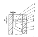
- a pump plunger 1 is sealingly guided in a plunger sleeve 5, which has a control bore 6.
- a cylindrical shoulder 7 At the pump plunger end 2 there is a cylindrical shoulder 7 and an oblique upper control edge 3.
- the arrangement works in the following way: When the fuel is being delivered, the plunger 1 moves upward in the plunger sleeve 5. The plunger end 2 first overflows the control bore 6 and closes it off. Because of the cylindrical shoulder 7, a gap t remains in the region of its height h, through which more or less fuel can flow back into the control bore 6. The amount of fuel that flows back depends on the delivery speed of the injection pump, ie on the speed of the engine. At low engine speed, the plunger 1 closes the control bore 6 only after passing through the height h of the cylindrical shoulder 7, while at high speed the control bore 6 is already closed by the pump plunger end 2. The delivery end is ended by the control bore 6 overflowing through the oblique control edge 4, since in this way the control bore 6 is connected to the delivery chamber 9 via the storage groove 8.
- the delivery rate of the injection pump is varied by the angular position of the rotatable plunger 1.
- the position of the upper oblique control groove 3 relative to the control bore 6 is changed by the rotation of the plunger 1 and thus the start of fuel delivery.
- the start of delivery with increasing injection quantity, i. H. increasing load adjusted early.
- the opposite inclination of the inclined upper control edge 3 the opposite is achieved.
- the arrangement according to the invention permits a change in the start of delivery of the injection pump that is dependent on the load and speed, without complex and space-consuming adjusting devices. In conjunction with the possible high injection pressures, this provides optimal conditions for low-consumption and low-pollution combustion.
Landscapes
- Engineering & Computer Science (AREA)
- Chemical & Material Sciences (AREA)
- Combustion & Propulsion (AREA)
- Mechanical Engineering (AREA)
- General Engineering & Computer Science (AREA)
- Fuel-Injection Apparatus (AREA)
Abstract
Description
Die Erfindung betrifft eine Kraftstoffeinspritzpumpe mit mindestens einem Pumpenplunger, insbesondere nach dem Oberbegriff des Anspruchs 1.The invention relates to a fuel injection pump with at least one pump plunger, in particular according to the preamble of
Einen wesentlichen Einfluß auf Wirtschaftlichkeit, Geräusch- und Abgasverhalten von direkt einspritzenden Dieselbrennkraftmaschinen hat der exakt eingehaltene optimale Förderbeginn. In der automobiltechnischen Zeitschrift Band 91, Heft 11, Seite 628 ff. wird ein Verfahren zur drehzahlabhängingen Förderbeginnverstellung beschrieben. Dabei wird die drehzahlabhängige Drosselung des Kraftstoffes an dem abgestuften Ende eines Pumpenplungers beim Schließen der Steuerbohrung in der Plungerbüchse ausgenutzt. Die Lösung hat den Vorteil, daß auf einen Fliehkraftspritzversteller verzichtet werden kann, der zumal bei den hohen Einspritzdrücken moderner Dieselbrennkraftmaschinen groß und teuer ist.The precisely observed optimal start of delivery has a significant influence on the economy, noise and exhaust behavior of direct-injection diesel engines. In the automotive engineering magazine Volume 91, Issue 11, page 628 ff., A method for speed-dependent delivery start adjustment is described. The speed-dependent throttling of the fuel at the stepped end of a pump plunger is used when the control bore in the plunger sleeve is closed. The solution has the advantage that a centrifugal force injection adjuster can be dispensed with, which is large and expensive, especially at the high injection pressures of modern diesel internal combustion engines.
Nachteilig an dieser Lösung ist, daß der Förderbeginn nur drehzahlabhängig verstellt wird.The disadvantage of this solution is that the start of delivery is only adjusted depending on the speed.
Daher ist es Aufgabe der vorliegenden Erfindung, zusätzlich zur drehzahlabhängigen Förderbeginnverstellung eine lastabhängige Förderbeginnverstellung zu verwirklichen.It is therefore an object of the present invention to implement a load-dependent delivery start adjustment in addition to the speed-dependent delivery start adjustment.
Die Aufgabe wird erfindungsgemäß gelöst durch das kennzeichnende Merkmal des Anspruchs 1. Die an sich bekannte schräge obere Steuerkante bewirkt in Verbindung mit dem zylindrischen Absatz am Pumpenplungerende eine lastabhängige Veränderung des Förderbeginns und der Verstellcharakteristik der Einspritzpumpe und bietet damit zusätzliche Parameter zur Optimierung der dieselmotorischen Verbrennung.The object is achieved according to the invention by the characterizing feature of
Eine vorteilhafte Weiterbildung der Erfindung betrifft das Ausmaß der lastabhängigen Förderbeginnverstellung. Dadurch können die diesbezüglichen Ansprüche von Dieselbrennkraftmaschinen in Saug- bzw. Aufladeversion und mit Ladeluftkühlung berücksichtigt werden.An advantageous development of the invention relates to the extent of the load-dependent delivery start adjustment. As a result, the relevant requirements of diesel internal combustion engines in the suction or supercharging version and with charge air cooling can be taken into account.
In einer vorteilhaften Ausbildung der Erfindung wird die Charakteristik der lastabhängigen Verstellung beeinflußt. Eine emissionsoptimale Auslegung erfordert normalerweise einen mit steigender Last späteren Förderbeginn, während eine verbrauchsoptimale Auslegung einen mit steigender Last früheren Förderbeginn notwendig macht. Beide Charakteristiken können durch entsprechende Neigung der oberen schrägen Steuerkante berücksichtigt werden.In an advantageous embodiment of the invention, the characteristic of the load-dependent adjustment is influenced. An emission-optimal design normally requires a later start of production with increasing load, while a consumption-optimal design requires an earlier start of production with increasing load. Both characteristics can be taken into account by appropriately inclining the upper oblique control edge.
Weitere Merkmale der Erfindung ergeben sich aus der folgenden Beschreibung und der Zeichnung, in der ein Ausführungsbeispiel der Erfindung schematisch dargestellt ist.Further features of the invention result from the following description and the drawing, in which an embodiment of the invention is shown schematically.
Die Figur zeigt:
- einen Schnitt durch eine
Plungerbüchse 5 mit einemPumpenplunger 1.
- a section through a
plunger sleeve 5 with apump plunger 1.
Ein Pumpenplunger 1 ist in einer Plungerbüchse 5 dichtend geführt, die eine Steuerbohrung 6 aufweist. Am Pumpenplungerende 2 ist ein zylindrischer Absatz 7 und eine schräge obere Steuerkante 3 angeordnet. Unterhalb des zylindrischen Absatzes 7 befindet sich am Pumpenplunger 1 eine Steuerkante 4, die über die Abstellnut 8 mit einem Förderraum 9 verbunden ist, der durch die Plungerbüchse 5 und den Pumpenplunger (1) begrenzt ist.A
Die Anordnung funktioniert auf folgende Weise:
Beim Fördern des Kraftstoffes bewegt sich der Plunger 1 in der Plungerbüchse 5 nach oben. Dabei überläuft zuerst das Plungerende 2, die Steuerbohrung 6 und schließt diese ab. Aufgrund des zylindrischen Absatzes 7 verbleibt im Bereich von dessen Höhe h ein Spalt t, durch den mehr oder weniger Kraftstoff in die Steuerbohrung 6 zurückströmen kann. Die Menge des zurückgeströmten Kraftstoffes richtet sich nach der Fördergeschwindigkeit der Einspritzpumpe, d. h. nach der Drehzahl des Motors. Bei niedriger Motordrehzahl schließt der Plunger 1 erst nach Durchlaufen der Höhe h des zylindrischen Absatzes 7 die Steuerbohrung 6 ab, während bei hoher Drehzahl die Steuerbohrung 6 schon durch das Pumpenplungerende 2 abgeschlossen wird. Das Förderende wird durch das Überlaufen der Steuerbohrung 6 durch die schräge Steuerkante 4 beendet, da auf diese Weise die Steuerbohrung 6 über die Abstellnut 8 mit dem Förderraum 9 verbunden ist.The arrangement works in the following way:
When the fuel is being delivered, the
Die Fördermenge der Einspritzpumpe wird durch die Winkellage des verdrehbaren Plungers 1 variiert. Gleichzeitig wird durch das Verdrehen des Plungers 1 auch die Lage der oberen schrägen Steuernut 3 zur Steuerbohrung 6 verändert und damit der Beginn der Kraftstofförderung. Im dargestellten Beispiel wird der Förderbeginn bei steigender Einspritzmenge, d. h. steigender Last nach früh verstellt. Bei umgekehrter Neigung der schrägen oberen Steuerkante 3 wird das Gegenteil verwirklicht.The delivery rate of the injection pump is varied by the angular position of the
Die erfindungsgemäße Anordnung gestattet, ohne aufwendige und platzraubende Verstelleinrichtungen eine last- und drehzahlabhängige Änderung des Förderbeginns der Einspritzpumpe. Damit sind in Verbindung mit den möglichen hohen Einspritzdrücken optimale Voraussetzungen für eine verbrauchsgünstige und schadstoffarme Verbrennung gegeben.The arrangement according to the invention permits a change in the start of delivery of the injection pump that is dependent on the load and speed, without complex and space-consuming adjusting devices. In conjunction with the possible high injection pressures, this provides optimal conditions for low-consumption and low-pollution combustion.
Claims (3)
dadurch gekennzeichnet, daß, ausgehend vom Pumpenplungerende (2), im Bereich des zylindrischen Absatzes (7) eine schräge obere Steuerkante (3) angeordnet ist, die zumindest in einem Teil des Verdrehbereichs des Pumpenplungers (1) die Steuerbohrung (6) beherrscht.Fuel injection pump with at least one pump plunger (1), which is sealingly guided in a plunger sleeve (5), which has a control bore (6), the pump plunger (1) terminating with a pump plunger end (2), to which a cylindrical shoulder (7 ) with a height h and a radial withdrawal depth t, whereby in cooperation with the control bore (6) the pump plunger end (2) determines the start of delivery, an inclined control edge (4) the delivery end and a rotation of the pump plunger (1) determine the delivery rate of the injection pump ,
characterized in that, starting from the pump plunger end (2), an oblique upper control edge (3) is arranged in the region of the cylindrical shoulder (7) and controls the control bore (6) at least in part of the range of rotation of the pump plunger (1).
dadurch gekennzeichnet, daß sich die schräge obere Steuerkante (3) vorzugsweise über die Höhe h des zylindrischen Absatzes (7) erstreckt.Injection pump according to claim 1,
characterized in that the inclined upper control edge (3) preferably extends over the height h of the cylindrical shoulder (7).
dadurch gekennzeichnet, daß die schräge obere Steuerkante (3) in Verdrehrichtung Vollast des Pumpenplungers (1) vorzugsweise fallend ausgebildet ist.Injection pump according to claim 1 or 2,
characterized in that the inclined upper control edge (3) in the direction of rotation full load of the pump plunger (1) is preferably designed to fall.
Applications Claiming Priority (1)
| Application Number | Priority Date | Filing Date | Title |
|---|---|---|---|
| DE19904008902 DE4008902A1 (en) | 1990-03-20 | 1990-03-20 | FUEL INJECTION PUMP |
Publications (2)
| Publication Number | Publication Date |
|---|---|
| EP0448066A2 true EP0448066A2 (en) | 1991-09-25 |
| EP0448066A3 EP0448066A3 (en) | 1991-11-06 |
Family
ID=6402628
Family Applications (1)
| Application Number | Title | Priority Date | Filing Date |
|---|---|---|---|
| EP19910104311 Withdrawn EP0448066A3 (en) | 1990-03-20 | 1991-03-20 | Fuel injection pump |
Country Status (2)
| Country | Link |
|---|---|
| EP (1) | EP0448066A3 (en) |
| DE (1) | DE4008902A1 (en) |
Citations (3)
| Publication number | Priority date | Publication date | Assignee | Title |
|---|---|---|---|---|
| DE2353193A1 (en) * | 1973-10-24 | 1975-05-07 | Heinrich Krauel | Fuel injector pump plunger - has regulator wedge to close fuel port in pump cylinder and to adjust injection timing |
| DE3332470A1 (en) * | 1982-09-08 | 1984-03-08 | Steyr-Daimler-Puch AG, 1011 Wien | Piston injection pump with helix control, especially for diesel engines |
| DE3732776A1 (en) * | 1987-09-29 | 1988-06-30 | Daimler Benz Ag | Bevel edge-controlled high-pressure injection pump for an air-compressing internal combustion engine with fuel injection |
Family Cites Families (3)
| Publication number | Priority date | Publication date | Assignee | Title |
|---|---|---|---|---|
| DE829681C (en) * | 1948-10-02 | 1952-01-28 | Bosch Gmbh Robert | Injection pump, especially for internal combustion engines |
| DE1749266U (en) * | 1956-01-17 | 1957-07-25 | Bosch Gmbh Robert | FUEL INJECTION PUMPS, IN PARTICULAR FOR INTERNAL IGNITION ENGINES FOR DRIVING VEHICLES. |
| EP0269610A1 (en) * | 1986-11-21 | 1988-06-01 | Robert Bosch Ag | Pump element of a fuel injection pump for an injection combustion engine |
-
1990
- 1990-03-20 DE DE19904008902 patent/DE4008902A1/en not_active Withdrawn
-
1991
- 1991-03-20 EP EP19910104311 patent/EP0448066A3/en not_active Withdrawn
Patent Citations (3)
| Publication number | Priority date | Publication date | Assignee | Title |
|---|---|---|---|---|
| DE2353193A1 (en) * | 1973-10-24 | 1975-05-07 | Heinrich Krauel | Fuel injector pump plunger - has regulator wedge to close fuel port in pump cylinder and to adjust injection timing |
| DE3332470A1 (en) * | 1982-09-08 | 1984-03-08 | Steyr-Daimler-Puch AG, 1011 Wien | Piston injection pump with helix control, especially for diesel engines |
| DE3732776A1 (en) * | 1987-09-29 | 1988-06-30 | Daimler Benz Ag | Bevel edge-controlled high-pressure injection pump for an air-compressing internal combustion engine with fuel injection |
Also Published As
| Publication number | Publication date |
|---|---|
| DE4008902A1 (en) | 1991-09-26 |
| EP0448066A3 (en) | 1991-11-06 |
Similar Documents
| Publication | Publication Date | Title |
|---|---|---|
| DE3300876A1 (en) | FUEL INJECTION PUMP | |
| DE2854422A1 (en) | FUEL INJECTION SYSTEM FOR DIESEL INTERNAL COMBUSTION ENGINES, ESPECIALLY FOR VEHICLE DIESEL ENGINES | |
| DE10000111C2 (en) | Control device for internal combustion engines | |
| DE3511328A1 (en) | FUEL INJECTION SYSTEM FOR DIESEL ENGINES | |
| DE3231853A1 (en) | FUEL SYSTEM FOR AUTO-IGNITION ENGINES | |
| EP0688950A1 (en) | Fuel injection system | |
| DE3013087A1 (en) | FUEL INJECTION PUMP FOR SELF-IGNITIONING INTERNAL COMBUSTION ENGINES | |
| EP0606435B1 (en) | Fuel injection pump for internal combustion engines | |
| EP0204117B1 (en) | Fuel injection pump for internal-combustion engines | |
| EP0155404A1 (en) | Regulating device for fuel injection pumps | |
| DE3424883A1 (en) | FUEL INJECTION PUMP FOR INTERNAL COMBUSTION ENGINES | |
| DE2946557A1 (en) | DEVICE FOR CONTROLLING AN EXHAUST GAS RECIRCULATION DEVICE IN INTERNAL COMBUSTION ENGINES | |
| DE4441506A1 (en) | Fuel injection pump | |
| EP0168586B1 (en) | Fuel injection pump | |
| EP0448066A2 (en) | Fuel injection pump | |
| DE2812176A1 (en) | DISTRIBUTOR INJECTION PUMP FOR A SELF-IGNING COMBUSTION ENGINE | |
| EP0515816B1 (en) | Fuel injection pump for internal combustion engines | |
| DE3424989C2 (en) | Fuel injection pump for internal combustion engines | |
| EP0320617A2 (en) | Governor for fuel injection pumps | |
| DE2658833A1 (en) | FUEL INJECTION SYSTEM FOR AIR COMPRESSING COMBUSTION ENGINES | |
| DE2107266C2 (en) | Camshaft drive for fuel injection pumps in internal combustion engines | |
| EP0627552A1 (en) | fuel injection pump | |
| EP0409943B1 (en) | Injection pump for diesel engines | |
| DE3141850A1 (en) | Pressure valve for a fuel injection pump | |
| EP0713002A1 (en) | High pressure fuel pump for internal combustion engines |
Legal Events
| Date | Code | Title | Description |
|---|---|---|---|
| PUAI | Public reference made under article 153(3) epc to a published international application that has entered the european phase |
Free format text: ORIGINAL CODE: 0009012 |
|
| PUAL | Search report despatched |
Free format text: ORIGINAL CODE: 0009013 |
|
| AK | Designated contracting states |
Kind code of ref document: A2 Designated state(s): AT DE FR GB IT |
|
| AK | Designated contracting states |
Kind code of ref document: A3 Designated state(s): AT DE FR GB IT |
|
| RAP1 | Party data changed (applicant data changed or rights of an application transferred) |
Owner name: KLOECKNER-HUMBOLDT-DEUTZ AG |
|
| STAA | Information on the status of an ep patent application or granted ep patent |
Free format text: STATUS: THE APPLICATION IS DEEMED TO BE WITHDRAWN |
|
| 18D | Application deemed to be withdrawn |
Effective date: 19920507 |