EP0269610A1 - Pump element of a fuel injection pump for an injection combustion engine - Google Patents
Pump element of a fuel injection pump for an injection combustion engine Download PDFInfo
- Publication number
- EP0269610A1 EP0269610A1 EP87890265A EP87890265A EP0269610A1 EP 0269610 A1 EP0269610 A1 EP 0269610A1 EP 87890265 A EP87890265 A EP 87890265A EP 87890265 A EP87890265 A EP 87890265A EP 0269610 A1 EP0269610 A1 EP 0269610A1
- Authority
- EP
- European Patent Office
- Prior art keywords
- piston
- pump
- suction
- overflow
- pump piston
- Prior art date
- Legal status (The legal status is an assumption and is not a legal conclusion. Google has not performed a legal analysis and makes no representation as to the accuracy of the status listed.)
- Withdrawn
Links
Images
Classifications
-
- F—MECHANICAL ENGINEERING; LIGHTING; HEATING; WEAPONS; BLASTING
- F02—COMBUSTION ENGINES; HOT-GAS OR COMBUSTION-PRODUCT ENGINE PLANTS
- F02M—SUPPLYING COMBUSTION ENGINES IN GENERAL WITH COMBUSTIBLE MIXTURES OR CONSTITUENTS THEREOF
- F02M55/00—Fuel-injection apparatus characterised by their fuel conduits or their venting means; Arrangements of conduits between fuel tank and pump F02M37/00
- F02M55/007—Venting means
-
- F—MECHANICAL ENGINEERING; LIGHTING; HEATING; WEAPONS; BLASTING
- F02—COMBUSTION ENGINES; HOT-GAS OR COMBUSTION-PRODUCT ENGINE PLANTS
- F02M—SUPPLYING COMBUSTION ENGINES IN GENERAL WITH COMBUSTIBLE MIXTURES OR CONSTITUENTS THEREOF
- F02M59/00—Pumps specially adapted for fuel-injection and not provided for in groups F02M39/00 -F02M57/00, e.g. rotary cylinder-block type of pumps
- F02M59/20—Varying fuel delivery in quantity or timing
- F02M59/24—Varying fuel delivery in quantity or timing with constant-length-stroke pistons having variable effective portion of stroke
- F02M59/26—Varying fuel delivery in quantity or timing with constant-length-stroke pistons having variable effective portion of stroke caused by movements of pistons relative to their cylinders
- F02M59/265—Varying fuel delivery in quantity or timing with constant-length-stroke pistons having variable effective portion of stroke caused by movements of pistons relative to their cylinders characterised by the arrangement or form of spill port of spill contour on the piston
Definitions
- the invention relates to a pump element of a fuel injection pump for injection internal combustion engines, in which the pump piston liner has at least one suction and overflow bore which is ground over by control edges of the pump piston, at least one control edge arranged in the region of the piston end face determining the start of delivery and at least one arranged on the piston jacket. in particular oblique, control edge determines the delivery end and wherein there is a throttled line connection between the working space of the pump piston and the suction and overflow bore during at least part of the pressure stroke of the pump piston.
- vapor bubbles or cavities form in the suction and overflow bores.
- the pump piston brings the fuel in the pump's working space to very high pressures of, for example, 1500 bar and more, and at the end of delivery this highly compressed fuel flows into the suction and overflow bore. If no precautions are taken to remove these vapor bubbles, they will implode as a result of the sudden increase in pressure in the suction and overflow bore, causing cavitation and erosion on the wall of the suction and overflow bore and also on the piston skirt and on the control edge.
- the object of the invention is to remove the vapor bubbles as early as possible and therefore as completely as possible from the suction and overflow bore.
- the invention essentially consists in the fact that the throttled line connection is formed by a surface recess emanating from the surface of the piston on the piston end face or by a surface recess on the piston running surface of the pump piston liner on the side of the suction and overflow bore facing the working space of the pump piston is, with the arrangement of the surface recess on the piston skirt, this extends only over areas which correspond to a rotational position of the pump piston with large injection quantities. This ensures that the vapor bubbles or cavities are removed from the suction and overflow bore as early as possible, etc.
- the pressure in the suction and overflow bore is also increased at an early stage to a lesser extent than at the end of the delivery, so that if such vapor bubbles are still in the overflow bore, they are softly imploded, which increases the risk of cavitation and erosion is reduced.
- the arrangement of a respective surface recess ensures that the steam bubbles are flushed away from the edges of the suction and overflow bore in the direction of the suction chamber.
- connection of the throttled line connection to the suction and overflow bore is preferably interrupted before the end of delivery, so that the fuel loss from the working area of the pump piston, which could change the delivery characteristic, if only slightly, is further reduced.
- the surface recess on the piston skirt expediently extends over an axial length which does not exceed the diameter of the suction and overflow bore. Such a dimensioning limits the duration of the overflow of the branched fuel and the fuel loss from the pump work area was kept low.
- the surface recess is arranged in the piston running surface of the pump piston liner, it expediently extends only over a circumferential region thereof which corresponds approximately to the diameter of the suction and overflow bore. In this way it is possible to effectively design the throttling effect of this surface recess.
- the depth of a surface recess which also determines the throttling effect, is 0.02 to 0.20%, preferably 0.10%, of the pump piston diameter.
- the arrangement can also be such that a circumferentially extending groove is arranged in the piston skirt just below the piston end face and is connected to the working space of the pump piston, for example via an axial groove.
- a circumferentially extending groove is arranged in the piston skirt just below the piston end face and is connected to the working space of the pump piston, for example via an axial groove.
- the distance of the groove running in the circumferential direction is therefore expediently smaller than half the diameter of the suction and overflow bore, and with such a dimensioning, the branched-off fuel will generally enter the suction and overflow bore at the start of delivery.
- the pump piston liner has two diametrically opposite suction and overflow bores
- the Control edges of the pump piston are arranged centrally symmetrically on both sides of the piston in order to avoid a one-sided high load on the pump piston, which leads to increased wear of the pump piston and the pump piston sleeve.
- the surface recess or the groove running in the circumferential direction are arranged in the area of both suction and overflow bores.
- 1 represents the piston which is guided in the pump piston liner 2 to move back and forth.
- the drive of the piston 1 is not shown.
- two diametrically opposite suction and overflow bores 3 are provided, with which the front edge 4 that determines the start of delivery and the oblique control grooves 5 that determine the end of delivery interact.
- the pump piston 1 assigns surface recesses 6, which have a depth a, on both sides in the areas interacting with the suction and overflow bores. These surface recesses are limited by edges 7.
- the depth a of the surface recess is indicated in the drawing for the sake of clarity and is in practice in a range between 0.02% and 0.2% of the pump piston diameter in order to ensure the desired throttling effect.
- a branched amount of fuel which is throttled in this surface recess 6, emerges from the working space 8 of the pump piston 1 into the suction and overflow bore 3 in the direction of arrow 9.
- vapor bubbles or cavities located in the suction and overflow bore 3 are flushed out of the suction and overflow bore 3 in the direction of the suction space.
- the suction and overflow bores 3 are opened by the oblique control edges 5, fuel jets entering the suction and overflow bores 3 under the high delivery pressure in the direction of arrow 10.
- the branched fuel jet emerging in the direction of arrow 9 deflects the fuel jet emerging at high pressure in the direction of arrow 10 from the wall of the suction and overflow bore 3.
- FIGS. 3 and 4 show an embodiment in which a surface recess 12 is provided not on the piston skirt but on the piston running surface 11 of the pump piston liner 2. A small amount of fuel emerges from this surface recess 12 already at the start of delivery, as a result of which the same effect is achieved as in the arrangement according to FIGS. 1 and 2.
- the recess 12 extends in the circumferential direction only over the width of the, as shown in FIG Suction and overflow bore 3, so that a more precise throttling can take place in this surface recess 12.
- circumferential grooves 13 are provided on the piston skirt 14 below the end edge 4 of the piston and are connected to the working space 8 of the piston 16 via grooves 15.
- the width and depth of the grooves 13 determine the throttling.
- the grooves 13 are arranged at a distance b from the piston end edge 4 which determines the conveying end. This distance b is smaller than the diameter of the suction and overflow bores 3, so that the fuel enters the suction and overflow bores 3 already at the start of delivery and conveys the vapor bubbles away there.
Abstract
Description
Die Erfindung bezieht sich auf ein Pumpenelement einer Brennstoffeinspritzpumpe für Einspritzbrennkraftmaschinen, bei welchem die Pumpenkolbenbüchse wenigstens eine Saug- und Überströmbohrung aufweist, die durch Steuerkanten des Pumpenkolbens überschliffen wird, wobei wenigstens eine im Bereich der Kolbenstirnfläche angeordnete Steuerkante den Förderbeginn und wenigstens eine am Kolbenmantel angeordnete, insbesondere schräge, Steuerkante das Förderende bestimmt und wobei während wenigstens eines Teiles des Druckhubes des Pumpenkolbens eine gedrosselte Leitungsverbindung zwischen dem Arbeitsraum des Pumpenkolbens und der Saug- und Überströmbohrung besteht.The invention relates to a pump element of a fuel injection pump for injection internal combustion engines, in which the pump piston liner has at least one suction and overflow bore which is ground over by control edges of the pump piston, at least one control edge arranged in the region of the piston end face determining the start of delivery and at least one arranged on the piston jacket. in particular oblique, control edge determines the delivery end and wherein there is a throttled line connection between the working space of the pump piston and the suction and overflow bore during at least part of the pressure stroke of the pump piston.
Durch den plötzlichen Abschluß der Saug- und Überströmbohrung bei Förderbeginn bilden sich Dampfblasen bzw. Hohlräume in der Saug- und Überströmbohrung. Durch den Pumpenkolben wird der Kraftstoff im Arbeitsraum der Pumpe auf sehr hohe Drücke von beispielsweise 1500 bar und auch mehr gebracht und bei Förderende strömt dieser hochkomprimierte Kraftstoff in die Saug- und Überströmbohrung. Wenn keine Vorsorge für die Wegförderung dieser Dampfblasen getroffen wird, implodieren dieselben infolge der plötzlichen Drucksteigerung in der Saug- und Überströmbohrung und es werden dadurch Kavitationen und Erosionen an der Wandung der Saug- und Überströmbohrung und auch am Kolbenmantel und an der Steuerkante verursacht. Aus der DE-OS 28 07 808 ist es bekannt geworden, Kraftstoff, der im Pumpenarbeitsraum unter Druck gesetzt wurde, über eine Drosselöffnung abzuzweigen und vor dem Aufsteuern der Saug- und Überströmbohrung in diese einzuführen, um die Dampfblasen aus dieser Saug- und Überströmbohrung wegzufördern. Bei dieser bekannten Anordnung gelangt der abgezweigte Brennstoff über Bohrungen im Kolben in eine Ausnehmung am Kolbenmantel und wird, sobald diese Ausnehmung die Saug- und Überström bohrung überschleift, in die Saug- und Überströmbohrung gefördert. Das Überschleifen der Saug- und Überströmbohrung durch diese Ausnehmung erfolgt aber erst verhältnismäßig knapp vor Förderende und es bleibt daher nicht genügend Zeit, um ein vollständiges Wegfördern der Dampfblasen aus der Saug- und Überströmlohrung zu gewährleisten.Due to the sudden completion of the suction and overflow bores at the start of delivery, vapor bubbles or cavities form in the suction and overflow bores. The pump piston brings the fuel in the pump's working space to very high pressures of, for example, 1500 bar and more, and at the end of delivery this highly compressed fuel flows into the suction and overflow bore. If no precautions are taken to remove these vapor bubbles, they will implode as a result of the sudden increase in pressure in the suction and overflow bore, causing cavitation and erosion on the wall of the suction and overflow bore and also on the piston skirt and on the control edge. From DE-OS 28 07 808 it has become known to branch off fuel that has been pressurized in the pump work space via a throttle opening and to introduce it into the suction and overflow bore in order to convey the vapor bubbles away from this suction and overflow bore . In this known arrangement, the branched fuel passes through bores in the piston into a recess on the piston skirt and, as soon as this recess, the suction and overflow bore grinded into the suction and overflow bore. The grinding of the suction and overflow bore through this recess takes place only relatively shortly before the end of the delivery and therefore there is not enough time to ensure that the vapor bubbles are completely removed from the suction and overflow bore.
Die Erfindung stellt sich zur Aufgabe, die Dampfblasen möglichst früh und daher möglichst vollständig aus der Saug- und Überströmbohrung wegzufördern. Zur Erfüllung dieser Aufgabe besteht die Erfindung im wesentlichen darin, daß die gedrosselte Leitungsverbindung von einer am Kolbenmantel von der Kolbenstirnfläche ausgehenden Oberlächenausnehmung oder von einer an der Kolbenlauffläche der Pumpenkolbenbüchse auf der dem Arbeitsraum des Pumpenkolbens zugewendeten Seite der Saug- und Überströmbohrung von dieser ausgehenden Oberflächenausnehmung gebildet wird, wobei bei Anordnung der Oberflächenausnehmung am Kolbenmantel diese sich nur über Bereiche erstreckt, welche einer Drehlage des Pumpenkolbens bei großen Einspritzmengen entsprechen. Dadurch wird erreicht, daß das Wegfördern der Dampfblasen bzw. Hohlräume aus der Saug- und Überströmbohrung möglichst frühzeitig erfolgt, u.zw. sofort nach Förderbeginn, so daß mehr Zeit zur Verfügung steht, um diese Dampfblasen möglichst vollständig aus der Saug- und Überströmbohrung zu entfernen. Es wird auch frühzeitig der Druck in der Saug- und Überströmbohrung in geringerem Maße als bei Förderende erhöht, so daß, wenn solche Dampfblasen sich noch in der Überströmbohrung befinden, diese zu einem weichen Implodieren gebracht werden, wodurch die Gefahr der Entstehung von Kavitationen und Erosionen verringert wird. Durch die Anordnung einer jeweiligen Oberflächenausnehmung wird sichergestellt, daß die Spülung der Dampfblasen von den Kanten der Saug- und Überströmbohrung weg in Richtung zum Saugraum erfolgt. Durch diese Oberflächenausnehmung gelangt Brennstoff in gedrosseltem Ausmaß bereits bei Förderbeginn in die Saug- und Über strömbohrung und es werden dadurch bereits bei Förderbeginn die Dampfblasen aus der Saug- und Überströmbohrung weggefördert, so daß genügend Zeit für die Wegförderung derselben verbleibt und die Gewähr gegeben ist, daß bei Förderende, wenn durch Aufsteuerung der Saug- und Überströmbohrung der Druck in dieser schlagartig erhöht wird, die Saug- und Überströmbohrung bereits zumindest weitgehend frei von Dampfblasen ist. Überdies wird bei einer solchen Ausbildung eine einfache Bearbeitung des Pumpenkolbens bzw. der Pumpenkolbenbüchse ermöglicht, da nur ein Anschliff des Kolbenmantels bzw. der Lauffläche der Pumpenkolbenbüchse erforderlich ist. Dadurch, daß bei Anordnung der Oberflächenausnehmung am Kolbenmantel diese sich nur über Bereiche erstreckt, welche einer Drehlage des Pumpenkolbens bei großen Einspritzmengen entsprechen, wird bewirkt, daß gezielt eine ordnungsgemäße Beseitigung der bei hohen Drehzahlen vermehrt auftretenden und daher besonders schädlichen Dampfblasen ermöglicht wird. Durch Begrenzung der Oberflächenausnehmung auf großen Einspritzmengen entsprechende Bereiche wird gleichzeitig eine ausreichende Drosselung erzielt, da die Abförderung der Dampfblasen unter weitestgehender Vermeidung einer Beeinträchtigung der Fördercharakteristik erfolgen soll.The object of the invention is to remove the vapor bubbles as early as possible and therefore as completely as possible from the suction and overflow bore. To achieve this object, the invention essentially consists in the fact that the throttled line connection is formed by a surface recess emanating from the surface of the piston on the piston end face or by a surface recess on the piston running surface of the pump piston liner on the side of the suction and overflow bore facing the working space of the pump piston is, with the arrangement of the surface recess on the piston skirt, this extends only over areas which correspond to a rotational position of the pump piston with large injection quantities. This ensures that the vapor bubbles or cavities are removed from the suction and overflow bore as early as possible, etc. immediately after the start of production, so that more time is available to remove these vapor bubbles as completely as possible from the suction and overflow bore. The pressure in the suction and overflow bore is also increased at an early stage to a lesser extent than at the end of the delivery, so that if such vapor bubbles are still in the overflow bore, they are softly imploded, which increases the risk of cavitation and erosion is reduced. The arrangement of a respective surface recess ensures that the steam bubbles are flushed away from the edges of the suction and overflow bore in the direction of the suction chamber. Through this surface recess, fuel gets into the suction and overflow to a restricted extent already at the start of delivery flow drilling and thereby the vapor bubbles are conveyed away from the suction and overflow bore at the start of production, so that there is sufficient time for the transport away and there is a guarantee that at the end of the delivery, if the suction and overflow drilling is activated, the pressure in it will be abrupt is increased, the suction and overflow bore is at least largely free of vapor bubbles. In addition, simple machining of the pump piston or the pump piston bushing is made possible with such a design, since only a grinding of the piston jacket or the running surface of the pump piston bushing is required. The fact that the arrangement of the surface recess on the piston skirt extends only over areas which correspond to a rotational position of the pump piston with large injection quantities has the effect that a targeted removal of the increasingly occurring and therefore particularly harmful vapor bubbles is made possible at high speeds. Adequate throttling is achieved at the same time by limiting the surface recess to areas corresponding to large quantities of injection, since the vapor bubbles are to be removed while largely preventing the delivery characteristics from being impaired.
Gemäß der Erfindung wird vorzugsweise die Verbindung der gedrosselten Leitungsverbindung mit der Saug- und Überströmbohrung bereits vor Förderende unterbrochen, so daß der Brennstoffverlust aus dem Arbeitsraum des Pumpenkolbens, welcher die Fördercharakteristik, wenn auch nur geringfügig, verändern könnte, weiter reduziert wird.According to the invention, the connection of the throttled line connection to the suction and overflow bore is preferably interrupted before the end of delivery, so that the fuel loss from the working area of the pump piston, which could change the delivery characteristic, if only slightly, is further reduced.
Zweckmäßig erstreckt sich gemäß der Erfindung die Oberflächenausnehmung am Kolbenmantel über eine axiale Länge, welche den Durchmesser der Saug- und Überströmbohrung nicht überschreitet. Durch eine solche Bemessung wird die Zeitdauer der Überströmung des abgezweigten Brennstoffes begrenzt und der Brennstoffverlust aus dem Pumpenarbeitsraum gering gehalten.According to the invention, the surface recess on the piston skirt expediently extends over an axial length which does not exceed the diameter of the suction and overflow bore. Such a dimensioning limits the duration of the overflow of the branched fuel and the fuel loss from the pump work area was kept low.
Wenn die Oberflächenausnehmung in der Kolbenlauffläche der Pumpenkolbenbüchse angeordnet ist, erstreckt sie sich zweckmäßig nur über einen Umfangsbereich desselben, der ungefähr dem Durchmesser der Saug- und Überströmbohrung entspricht. Auf diese Weise wird es ermöglicht, den Drosseleffekt dieser Oberflächenausnehmung wirksam zu gestalten.If the surface recess is arranged in the piston running surface of the pump piston liner, it expediently extends only over a circumferential region thereof which corresponds approximately to the diameter of the suction and overflow bore. In this way it is possible to effectively design the throttling effect of this surface recess.
Die Tiefe einer Oberflächenausnehmung, welche auch den Drosseleffekt bestimmt, beträgt gemäß einer bevorzugten Ausführungsform 0,02 bis 0,20 %, vorzugsweise 0,10 %, des Pumpenkolbendurchmessers.According to a preferred embodiment, the depth of a surface recess, which also determines the throttling effect, is 0.02 to 0.20%, preferably 0.10%, of the pump piston diameter.
Bei einer anderen Ausführungsform entsprechend der Erfindung kann die Anordnung auch so getroffen sein, daß knapp unterhalb der Kolbenstirnfläche eine in Umfangsrichtung verlaufende Nut im Kolbenmantel angeordnet ist, welche mit dem Arbeitsraum des Pumpenkolbens, beispielsweise über eine Axialnut, in Verbindung steht. In diesem Falle wird auch der Effekt erreicht, daß der abgezweigte Brennstoff bereits knapp nach Förderbeginn oder schon bei Förderbeginn in die Saug- und Überströmbohrung gelangt, während durch entsprechende Bemessung der Nut der erforderliche Drosselquerschnitt erzielbar ist. Gemäß der Erfindung ist daher zweckmäßig der Abstand der in Umfangsrichtung verlaufenden Nut kleiner als der halbe Durchmesser der Saug- und Überströmbohrung und bei einer solchen Bemessung wird im allgemeinen der abgezweigte Brennstoff bereits bei Förderbeginn in die Saug- und Überströmbohrung gelangen.In another embodiment according to the invention, the arrangement can also be such that a circumferentially extending groove is arranged in the piston skirt just below the piston end face and is connected to the working space of the pump piston, for example via an axial groove. In this case, the effect is achieved that the branched fuel reaches the suction and overflow bore just after the start of delivery or already at the start of delivery, while the required throttle cross section can be achieved by appropriate dimensioning of the groove. According to the invention, the distance of the groove running in the circumferential direction is therefore expediently smaller than half the diameter of the suction and overflow bore, and with such a dimensioning, the branched-off fuel will generally enter the suction and overflow bore at the start of delivery.
Bei Brennstoffeinspritzpumpen, welche mit hohen Drücken, wie beispielsweise 1500 bar oder darüber arbeiten, ist es zweckmäßig, daß die Pumpenkolbenbüchse zwei diametral gegenüberliegende Saug- und Überströmbohrungen aufweist, wobei die Steuerkanten des Pumpenkolbens zentralsymmetrisch an beiden Kolbenseiten angeordnet sind, um eine einseitige hohe Belastung des Pumpenkolbens, welche zu einem erhöhten Verschleiß des Pumpenkolbens und der Pumpenkolbenbüchse führt, zu vermeiden. Bei solchen Pumpenelementen sind gemäß der Erfindung die Oberflächenausnehmung oder die in Umfangsrichtung verlaufende Nut im Bereich beider Saug- und Überströmbohrungen angeordnet. Bei solchen, mit hohen Drücken arbeitenden Pumpenelementen ist die Gefahr der Entstehung von Kavitationen und Erosionen besonders groß und es ist daher wesentlich, daß diese Gefahr im Bereich der beiden Saug- und Überströmbohrungen ausgeschaltet wird.In fuel injection pumps, which operate at high pressures, such as 1500 bar or above, it is expedient that the pump piston liner has two diametrically opposite suction and overflow bores, the Control edges of the pump piston are arranged centrally symmetrically on both sides of the piston in order to avoid a one-sided high load on the pump piston, which leads to increased wear of the pump piston and the pump piston sleeve. In such pump elements, according to the invention, the surface recess or the groove running in the circumferential direction are arranged in the area of both suction and overflow bores. With such pump elements working at high pressures, the risk of cavitation and erosion is particularly great and it is therefore essential that this danger is eliminated in the area of the two suction and overflow bores.
In der Zeichnung ist die Erfindung an Hand von Ausführungsbeispielen schematisch erläutert.
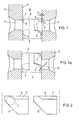
- Fig. 1 und 1a zeigen einen Axialschnitt durch Pumpenkolben und Pumpenkolbenbüchse im Bereich der Saug- und Überströmbohrungen, wobei Fig.1 die Kolbenstellung knapp nach Förderbeginn und Fig.1a die Kolbenstellung bei Förderende darstellt;
- Fig. 2 zeigt eine Abwickelung des Kolbenmantels gemäß Fig.1;
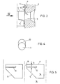
- Fig. 3 und 4 zeigen eine abgewandelte Ausführungsform, wobei Fig.3 einen Teilschnitt durch die Pumpenkolbenbüchse
- und Fig.4 eine Ansicht der Lauffläche der Pumpenkolbenbüchse in Richtung des Pfeiles IV der Fig.3 darstellt;
- Fig.5 zeigt eine andere Ausführungsform in Form einer Abwicklung des Pumpenkolbenmantels.
- 1 and 1a show an axial section through the pump piston and pump piston sleeve in the area of the suction and overflow bores, with FIG. 1 showing the piston position just after the start of delivery and FIG. 1a the piston position at the end of delivery;
- Fig. 2 shows a development of the piston skirt according to Fig.1;
- 3 and 4 show a modified embodiment, wherein Fig.3 shows a partial section through the pump piston liner
- and Figure 4 is a view of the tread of the pump piston liner in the direction of arrow IV of Figure 3;
- 5 shows another embodiment in the form of a development of the pump piston jacket.
Bei der Ausführungsform nach Fig.1, 1a und 2 stellt 1 den Kolben dar, der in der Pumpenkolbenbüchse 2 zu hin- und hergehender Bewegung geführt ist. Der Antrieb des Kolbens 1 ist nicht dargestellt. In der Pumpenkolbenbüchse 2 sind zwei diametral gegenüberliegende Saug- und Überströmbohrungen 3 vorgesehen, mit welchen die den Förderbeginn bestimmende Stirnkante 4 und die das Förderende bestimmenden schrägen Steuernuten 5 zusammenwirken. Der Pumpenkolben 1 weist zu beiden Seiten in dem mit den Saug- und Überströmbohrungen zusammenwirkenden Bereichen Oberflächenausnehmungen 6 auf, welche eine Tiefe a aufweisen. Diese Oberflächenausnehmungen sind durch Kanten 7 begrenzt. Die Tiefe a der Oberflächenausnehmung ist in der Zeichnung der Deutlichkeit halber stark vergrößert angedeutet und liegt in der Praxis in einem Bereich zwischen 0,02 % und 0,2 % des Pumpenkolbendurchmessers, um den gewünschten Drosseleffekt sicherzustellen.In the embodiment according to FIGS. 1, 1a and 2, 1 represents the piston which is guided in the
Durch diese Oberflächenausnehmungen 6 tritt bei Förderbeginn aus dem Arbeitsraum 8 des Pumpenkolbens 1 eine abgezweigte Brennstoffmenge, welche in dieser Oberflächenausnehmung 6 gedrosselt wird, in die Saug- und Überströmbohrung 3 in Richtung des Pfeiles 9 aus. Durch diese abgezweigte Brennstoffmenge werden in der Saug- und Überströmbohrung 3 befindliche Dampfblasen bzw. Hohlräume aus der Saug- und Überströmbohrung 3 in Richtung zum Saugraum herausgespült. Bei Förderende (Fig.1a) werden durch die schrägen Steuerkanten 5 die Saug- und Überströmbohrungen 3 aufgesteuert, wobei Brennstoffstrahlen unter dem hohen Förderdruck in Richtung des Pfeiles 10 in die Saug- und Überströmbohrungen 3 eintreten. Durch den in Richtung des Pfeiles 9 austretenden abgezweigten Brennstoffstrahl wird der in Richtung des Pfeiles 10 unter hohem Druck austretende Brennstoffstrahl von der Wandung der Saug- und Überströmbohrung 3 abgelenkt.Through these
Fig.3 und 4 zeigen eine Ausführungsform, bei welcher nicht am Kolbenmantel, sondern an der Kolbenlauffläche 11 der Pumpenkolbenbüchse 2 eine Oberflächenausnehmung 12 vorgesehen ist. Über diese Oberflächenausnehmung 12 tritt bereits bei Förderbeginn eine geringfügige Brennstoffmenge aus, wodurch der gleiche Effekt erzielt wird wie bei der Anordnung nach Fig.1 und 2. Die Ausnehmung 12 erstreckt sich hiebei, wie Fig.4 zeigt, in Umfangsrichtung nur über die Breite der Saug- und Überströmbohrung 3, so daß in dieser Oberflächenausnehmung 12 eine präzisere Drosselung erfolgen kann.3 and 4 show an embodiment in which a surface recess 12 is provided not on the piston skirt but on the
Bei der Ausführungsform nach Fig.5 sind unterhalb der Stirnkante 4 des Kolbens in Umfangsrichtung verlaufende Nuten 13 am Kolbenmantel 14 vorgesehen, welche über Nuten 15 mit dem Arbeitsraum 8 des Kolbens 16 in Verbindung stehen. Die Breite und Tiefe der Nuten 13 bestimmt die Drosselung. Die Nuten 13 sind in einem Abstand b von der das Förderende bestimmenden Kolbenstirnkante 4 angeordnet. Dieser Abstand b ist kleiner als der Durchmesser der Saug- und Überströmbohrungen 3, so daß der Brennstoff über die Ausnehmung 12 bereits bei Förderbeginn in die Saug- und Überströmbohrungen 3 eintritt und dort die Dampfblasen wegfördert.In the embodiment according to FIG. 5,
Claims (8)
Applications Claiming Priority (2)
| Application Number | Priority Date | Filing Date | Title |
|---|---|---|---|
| AT312086 | 1986-11-21 | ||
| AT3120/86 | 1986-11-21 |
Publications (1)
| Publication Number | Publication Date |
|---|---|
| EP0269610A1 true EP0269610A1 (en) | 1988-06-01 |
Family
ID=3545614
Family Applications (1)
| Application Number | Title | Priority Date | Filing Date |
|---|---|---|---|
| EP87890265A Withdrawn EP0269610A1 (en) | 1986-11-21 | 1987-11-20 | Pump element of a fuel injection pump for an injection combustion engine |
Country Status (1)
| Country | Link |
|---|---|
| EP (1) | EP0269610A1 (en) |
Cited By (7)
| Publication number | Priority date | Publication date | Assignee | Title |
|---|---|---|---|---|
| DE3902764A1 (en) * | 1989-01-31 | 1990-08-02 | Bosch Gmbh Robert | FUEL INJECTION PUMP |
| US4957418A (en) * | 1988-06-18 | 1990-09-18 | Robert Bosch Gmbh | Injection pump for internal combustion engines |
| GB2235955A (en) * | 1989-07-14 | 1991-03-20 | Daimler Benz Ag | Sloping-edge-controlled fuel injection pump for internal combustion engines |
| DE4006899A1 (en) * | 1990-03-06 | 1991-09-12 | Mak Maschinenbau Krupp | Piston for fuel injection pump - has increased radial clearance over end region to eliminate cavitation |
| DE4008902A1 (en) * | 1990-03-20 | 1991-09-26 | Kloeckner Humboldt Deutz Ag | FUEL INJECTION PUMP |
| DE4127032A1 (en) * | 1991-08-16 | 1993-02-18 | Bosch Gmbh Robert | FUEL INJECTION PUMP FOR INTERNAL COMBUSTION ENGINES |
| US5286178A (en) * | 1992-03-05 | 1994-02-15 | Robert Bosch Gmbh | Fuel injection pump for internal combustion engines |
Citations (6)
| Publication number | Priority date | Publication date | Assignee | Title |
|---|---|---|---|---|
| FR788268A (en) * | 1935-03-08 | 1935-10-07 | Bosch Robert | Injection pump for diesel engines |
| FR1054678A (en) * | 1952-01-21 | 1954-02-12 | Caterpillar Tractor Co | Advanced injection pump |
| AT311727B (en) * | 1971-11-04 | 1973-11-26 | List Hans | Injection pump for diesel engines |
| FR2200446A1 (en) * | 1972-09-20 | 1974-04-19 | Maschf Augsburg Nuernberg Ag | |
| GB2133478A (en) * | 1983-01-08 | 1984-07-25 | Lucas Ind Plc | Fuel injection pumps |
| GB2135395A (en) * | 1983-02-14 | 1984-08-30 | Steyr Daimler Puch Ag | Fuel-injection unit for each cylinder of a diesel engine |
-
1987
- 1987-11-20 EP EP87890265A patent/EP0269610A1/en not_active Withdrawn
Patent Citations (6)
| Publication number | Priority date | Publication date | Assignee | Title |
|---|---|---|---|---|
| FR788268A (en) * | 1935-03-08 | 1935-10-07 | Bosch Robert | Injection pump for diesel engines |
| FR1054678A (en) * | 1952-01-21 | 1954-02-12 | Caterpillar Tractor Co | Advanced injection pump |
| AT311727B (en) * | 1971-11-04 | 1973-11-26 | List Hans | Injection pump for diesel engines |
| FR2200446A1 (en) * | 1972-09-20 | 1974-04-19 | Maschf Augsburg Nuernberg Ag | |
| GB2133478A (en) * | 1983-01-08 | 1984-07-25 | Lucas Ind Plc | Fuel injection pumps |
| GB2135395A (en) * | 1983-02-14 | 1984-08-30 | Steyr Daimler Puch Ag | Fuel-injection unit for each cylinder of a diesel engine |
Cited By (10)
| Publication number | Priority date | Publication date | Assignee | Title |
|---|---|---|---|---|
| US4957418A (en) * | 1988-06-18 | 1990-09-18 | Robert Bosch Gmbh | Injection pump for internal combustion engines |
| DE3902764A1 (en) * | 1989-01-31 | 1990-08-02 | Bosch Gmbh Robert | FUEL INJECTION PUMP |
| DE3902764C2 (en) * | 1989-01-31 | 2002-10-17 | Bosch Gmbh Robert | Fuel injection pump |
| GB2235955A (en) * | 1989-07-14 | 1991-03-20 | Daimler Benz Ag | Sloping-edge-controlled fuel injection pump for internal combustion engines |
| GB2235955B (en) * | 1989-07-14 | 1993-08-04 | Daimler Benz Ag | Sloping-edge-controlled fuel injection pump for internal combustion engines |
| DE4006899A1 (en) * | 1990-03-06 | 1991-09-12 | Mak Maschinenbau Krupp | Piston for fuel injection pump - has increased radial clearance over end region to eliminate cavitation |
| DE4008902A1 (en) * | 1990-03-20 | 1991-09-26 | Kloeckner Humboldt Deutz Ag | FUEL INJECTION PUMP |
| DE4127032A1 (en) * | 1991-08-16 | 1993-02-18 | Bosch Gmbh Robert | FUEL INJECTION PUMP FOR INTERNAL COMBUSTION ENGINES |
| DE4127032C2 (en) * | 1991-08-16 | 1999-06-02 | Bosch Gmbh Robert | Fuel injection pump for internal combustion engines |
| US5286178A (en) * | 1992-03-05 | 1994-02-15 | Robert Bosch Gmbh | Fuel injection pump for internal combustion engines |
Similar Documents
| Publication | Publication Date | Title |
|---|---|---|
| EP0301310B1 (en) | Axial piston machine of the plate or inclined axis type with distribution slots and pressure compensation canals | |
| EP0461212A1 (en) | Electrically controlled fuel injection pump for internal combustion engines, especially pump nozzle. | |
| DE3804843A1 (en) | FUEL INJECTION PUMP FOR INTERNAL COMBUSTION ENGINES | |
| CH679415A5 (en) | ||
| DE3809700C2 (en) | ||
| DE69818382T2 (en) | INJEKTOR | |
| EP0269610A1 (en) | Pump element of a fuel injection pump for an injection combustion engine | |
| EP0263304B1 (en) | Fuel injection pump for internal combustion engines | |
| EP0263807B1 (en) | Pump element of a fuel pump for an injection combustion engine | |
| EP0270519B1 (en) | Pump element of a fuel injection pump for an injection combustion engine | |
| DE2532205C3 (en) | Fuel injection pump for diesel internal combustion engines | |
| EP0971123B1 (en) | Fuel injection pump | |
| EP0372211B1 (en) | Fuel injection pump for injection internal-combustion engines | |
| DE3644150C2 (en) | Fuel injection pump for internal combustion engines | |
| DE3734926C2 (en) | ||
| EP0263808B1 (en) | Pump element of a fuel pump for an injection combustion engine | |
| DE3928375C2 (en) | Piston pump | |
| DE3707731C2 (en) | ||
| EP0444256B1 (en) | Fuel injection device for injection-type internal combustion engines | |
| DE1208554B (en) | Pump element for injection pumps | |
| WO1991015675A1 (en) | Fuel injection device for internal combustion engines | |
| EP0370263B1 (en) | Pumping element of a fuel injection pump for internal-combustion engines | |
| DE4006899A1 (en) | Piston for fuel injection pump - has increased radial clearance over end region to eliminate cavitation | |
| DE2003958C3 (en) | Fuel injection pump for internal combustion engines | |
| DE722128C (en) | Fuel injection pump for internal combustion engines |
Legal Events
| Date | Code | Title | Description |
|---|---|---|---|
| PUAI | Public reference made under article 153(3) epc to a published international application that has entered the european phase |
Free format text: ORIGINAL CODE: 0009012 |
|
| AK | Designated contracting states |
Kind code of ref document: A1 Designated state(s): AT DE FR GB |
|
| STAA | Information on the status of an ep patent application or granted ep patent |
Free format text: STATUS: THE APPLICATION IS DEEMED TO BE WITHDRAWN |
|
| 18D | Application deemed to be withdrawn |
Effective date: 19890302 |
|
| RIN1 | Information on inventor provided before grant (corrected) |
Inventor name: STIPEK, THEODOR, DIPL.-ING. DR. |