EP0447381A1 - Door for an electric switch cabinet - Google Patents
Door for an electric switch cabinet Download PDFInfo
- Publication number
- EP0447381A1 EP0447381A1 EP91850039A EP91850039A EP0447381A1 EP 0447381 A1 EP0447381 A1 EP 0447381A1 EP 91850039 A EP91850039 A EP 91850039A EP 91850039 A EP91850039 A EP 91850039A EP 0447381 A1 EP0447381 A1 EP 0447381A1
- Authority
- EP
- European Patent Office
- Prior art keywords
- door
- hinge
- radius
- door leaf
- latch means
- Prior art date
- Legal status (The legal status is an assumption and is not a legal conclusion. Google has not performed a legal analysis and makes no representation as to the accuracy of the status listed.)
- Granted
Links
- 238000010276 construction Methods 0.000 claims abstract description 39
- 239000000463 material Substances 0.000 claims abstract description 12
- 238000007789 sealing Methods 0.000 claims abstract description 9
- 230000000295 complement effect Effects 0.000 claims abstract description 6
- 229910052751 metal Inorganic materials 0.000 claims abstract description 6
- 239000002184 metal Substances 0.000 claims abstract description 6
- 229910000831 Steel Inorganic materials 0.000 description 5
- 239000010959 steel Substances 0.000 description 5
- 239000007789 gas Substances 0.000 description 4
- 229910000639 Spring steel Inorganic materials 0.000 description 3
- 238000005553 drilling Methods 0.000 description 3
- 238000010891 electric arc Methods 0.000 description 3
- 231100000614 poison Toxicity 0.000 description 3
- 230000007096 poisonous effect Effects 0.000 description 3
- 229920002522 Wood fibre Polymers 0.000 description 2
- 238000005452 bending Methods 0.000 description 2
- 239000011505 plaster Substances 0.000 description 2
- 230000000717 retained effect Effects 0.000 description 2
- 230000035939 shock Effects 0.000 description 2
- 229910052782 aluminium Inorganic materials 0.000 description 1
- XAGFODPZIPBFFR-UHFFFAOYSA-N aluminium Chemical compound [Al] XAGFODPZIPBFFR-UHFFFAOYSA-N 0.000 description 1
- 238000004873 anchoring Methods 0.000 description 1
- 238000005352 clarification Methods 0.000 description 1
- 150000001875 compounds Chemical class 0.000 description 1
- 230000000694 effects Effects 0.000 description 1
- 239000011810 insulating material Substances 0.000 description 1
- 238000009413 insulation Methods 0.000 description 1
- 238000003466 welding Methods 0.000 description 1
Images

Classifications
-
- E—FIXED CONSTRUCTIONS
- E05—LOCKS; KEYS; WINDOW OR DOOR FITTINGS; SAFES
- E05F—DEVICES FOR MOVING WINGS INTO OPEN OR CLOSED POSITION; CHECKS FOR WINGS; WING FITTINGS NOT OTHERWISE PROVIDED FOR, CONCERNED WITH THE FUNCTIONING OF THE WING
- E05F7/00—Accessories for wings not provided for in other groups of this subclass
- E05F7/02—Accessories for wings not provided for in other groups of this subclass for raising wings before being turned
-
- E—FIXED CONSTRUCTIONS
- E05—LOCKS; KEYS; WINDOW OR DOOR FITTINGS; SAFES
- E05D—HINGES OR SUSPENSION DEVICES FOR DOORS, WINDOWS OR WINGS
- E05D1/00—Pinless hinges; Substitutes for hinges
- E05D1/04—Pinless hinges; Substitutes for hinges with guide members shaped as circular arcs
-
- H—ELECTRICITY
- H02—GENERATION; CONVERSION OR DISTRIBUTION OF ELECTRIC POWER
- H02B—BOARDS, SUBSTATIONS OR SWITCHING ARRANGEMENTS FOR THE SUPPLY OR DISTRIBUTION OF ELECTRIC POWER
- H02B1/00—Frameworks, boards, panels, desks, casings; Details of substations or switching arrangements
- H02B1/26—Casings; Parts thereof or accessories therefor
- H02B1/30—Cabinet-type casings; Parts thereof or accessories therefor
- H02B1/38—Hinged covers or doors
-
- E—FIXED CONSTRUCTIONS
- E05—LOCKS; KEYS; WINDOW OR DOOR FITTINGS; SAFES
- E05Y—INDEXING SCHEME ASSOCIATED WITH SUBCLASSES E05D AND E05F, RELATING TO CONSTRUCTION ELEMENTS, ELECTRIC CONTROL, POWER SUPPLY, POWER SIGNAL OR TRANSMISSION, USER INTERFACES, MOUNTING OR COUPLING, DETAILS, ACCESSORIES, AUXILIARY OPERATIONS NOT OTHERWISE PROVIDED FOR, APPLICATION THEREOF
- E05Y2900/00—Application of doors, windows, wings or fittings thereof
- E05Y2900/20—Application of doors, windows, wings or fittings thereof for furniture, e.g. cabinets
- E05Y2900/208—Application of doors, windows, wings or fittings thereof for furniture, e.g. cabinets for metal cabinets
-
- H—ELECTRICITY
- H02—GENERATION; CONVERSION OR DISTRIBUTION OF ELECTRIC POWER
- H02B—BOARDS, SUBSTATIONS OR SWITCHING ARRANGEMENTS FOR THE SUPPLY OR DISTRIBUTION OF ELECTRIC POWER
- H02B13/00—Arrangement of switchgear in which switches are enclosed in, or structurally associated with, a casing, e.g. cubicle
- H02B13/02—Arrangement of switchgear in which switches are enclosed in, or structurally associated with, a casing, e.g. cubicle with metal casing
- H02B13/025—Safety arrangements, e.g. in case of excessive pressure or fire due to electrical defect
Definitions
- This invention relates to a door for an electric switch cabinet, comprising a door leaf made from sheet metal and/or other arc and fire insulating material, a hinge construction provided at a vertical longitudinal edge of the door leaf and connectable to the frame of the cabinet, and a locking device cooperating with the frame and provided at the opposite vertical edge of the door.
- the cabinet doors are hinged by longitudinal hinges of the piano hinge type which are bolted or spot welded to the cabinet frame and the door.
- a hinge is not completely gas-tight and might also be a component of inferior strength in the door construction that, together with the cabinet, should encase the electric equipment for protection against burning-through, pressure shocks and exiting poisonous gases.
- An object of the present invention is to provide a door for an electric switch cabinet of the kind described above, which door has an improved hinge construction and is lockable from all sides to the frame of the switch cabinet.
- the door shown in FIG.1 comprises a door leaf 10 the one vertival edge of which is connected to a hinge construction 30 and at the other edge connected to a locking construction 70. In its closed position the door is designed to cover an opening 104 (FIG.2 and 3) defined by a frame construction 102 of a switch cabinet generally designed by reference numeral 100 and shown only fragmentarily.
- the locking construction 70 is not mounted in the door leaf 10 itself but incorporated in an independent constructional part comprising a profiled or shaped metal element 42, preferably an extruded aluminum profile, extending throughout the height of the door.
- the profile 72 (FIG.6) has a closed channel 78 at the outside of the door and an open channel 74, 76 opening towards the longitudinal edge portion of the door leaf 10.
- the inner portion 76 of the open channel is intended for receiving a locking bar 90 (described later), and the outer portion 74 of the open channel is used as a recess for receiving the corresponding edge portion 20 (FIG.3) of the door leaf 10.
- a shoulder or flange 86 located between the channel portions 74 and 76 is acting as a stop for the edge portion 20.
- the locking bar 90 shown in FIG.3 extends substantially throughout the length of the profile 70 and is preferably bolted to the profile 70 by countersunk screws from the inside of the door (not shown). Moreover, in the locking bar 90 and in the inside flange of the the profile 72, a plurality of key-hole shaped recesses (one only is shown) are provided spaced along the profile 72, each recess comprising a vertical slot 92 which is downwards widened to a circular hole 94.
- each key-hole recess 92, 94 is arranged to engage a corresponding locking member 96 having an enlarged head portion and protruting through an opening 106 from the frame construction 102.
- the opposite end of each locking member 96 is received in a respective bore 110 of a retaining bar 118 and secured thereto by a nut 98 at the threaded end thereof.
- the retaining bar 108 is in turn preferably bolted by countersunk screws at the front side of the frame construction 102.
- the opening 106 preferably has an oversize such that the retaining bar 108 and the respective locking members 96 can be adjusted relative the key-hole recesses 92, 94.
- the hinge device 30 is designed as closed profile element hinge consisting of two metal profiles 32, 60 extending over the full height of the door.
- the door profile 32 (FIG.7) of the hinge construction 30, has, like the profile 72 of the locking construction, a closed longitudinal channel 46 provided at the outside of the door and a longitudinal channel 42 opening to the corresponding edge portion 22 (FIG.3) of the door leaf 10 to receive this edge portion 22.
- the depth of the open channel 42 is delimited by a stop 56 provided at one side of the channel.
- Screw pockets 48 and 50 are provided at the bottom of the closed channel 46 and the open channel 42, respectively, for allowing a cover plate indicated in FIG.1 to be screwed onto the top end of profile 32.
- the profile 32 Laterally outside the closed channel 46, the profile 32 has a hinge portion 34.
- the profiles 32, 72 are provided with the closed channels 46 and 78 at the respective opposite longitudinal edges of the outside of the door leaf 10, the profiles are given a good bending and torsional rigidity, whereby they are able to stiffen or strengthen the longitudinal edge portions of the door.
- the outside of hinge portion 34 of profile 32 together with the outside of the wall portions of closed channel 46 form a trapezoid ledge or strip that is symmetrical to the trapezoid ledge formed by the outside of the wall portions of the channel 78 of the profile 72 at the opposite longitudinal edge of the door leaf 10.
- the door is thereby also rendered an attractive appearance.
- the cabinet profile 60 of the hinge construction 30 has a flange 64 (FIG.8) connectable to the frame construction 102, and a hinge portion 62 complementary to the hinge portion 34 of the door profile 32.
- the interengaging hinge portions 34 and 62 which can be assembled only by being inserted axially sliding into each other, and consequently are radially interlocked to each other, are shown on a larger scale in FIG.9.
- Each of said portions 34 and 62 is formed approximately as a spiral having mutually cooperating partly circular (circular cylindrical as seen in three dimensions) bearing surfaces situated at different radial distances from the pivot bearing axis defined thereby.
- the outer spiral portion 34 has an entering subcircular surface A having a large radius R1.
- the sub-circular inner surface is transformed via a flat surface B to a koaxial sub-circular inner surface C having a small radius R3.
- Profile 34 then continues by a sub-circular outer surface D being opposite to inner surface C and having an intermediate radius R2, and by a plane outer surface E being opposite to flat inner surface B .
- the inner spiral portion 62 in turn has a pair of opposite initially sub-circular outer and inner respective surfaces a and d adapted to cooperate with the respective surfaces A and D of the profile 34 at the radii R1 and R2, an ending sub-circular surface c adapted to cooperate with the surface C of the profile 34 at the radius R3, and a flat surface b extending between surfaces a and c and adapted to cooperate with the flat surface B of profile 34 as an end stop in the closed position of the hinge.
- the inner surface D of the profile 62 is preceded by a flat surface e adapted to cooperate with the flat surface E of profile 34, as indicated by the swung-out profile 32 shown by phantom lines in FIG.8.
- the hinge is given a very sturdy construction having three coaxial pairs of bearing surfaces A - a , C - c and D - d that simultanously are in engagement with each other over substantially the whole operational area of the hinge.
- the mutually cooperating spiral shaped portions 34, 62 function as stiffening elements which prevent the door from outward bending in case of large forces and pressures inside the cabinet, whereby fire-generating and poisonous gases are prevented from issuing out of the cabinet.
- the hinge has also a specific security function against exiting gas in such extent that the sealing action obtained by the plurality of the cooperating pairs of successive bearing surfaces of the profiles 24 and 62 is enhanced by the pressure generated for example by an electric arc in the cabinet space encased by the door, by virtue of thereby at least some hinge surfaces are pressed against each other.
- the cabinet profile 60 of the hinge construction 30 is in a suitably manner secured to the frame construction 102 by threaded fasteners 112 (FIG.3).
- the flange 64 of the cabinet profile 60 is provided with a longitudinal drilling indication groove 68 and a retaining shoulder 66 for locking engagement with the respective faces of the bolt heads of fasteners 112.
- Corresponding longitudinal drilling indication grooves are also provided at 82 and 52 on the inner flanges 84 and 54 of the profiles 72 and 32, respectively (FIG.6 and FIG.7).
- the profiles 32 and 72 can be secured to the door leaf by means of blind rivets 114 which, after drilling of connection holes through the profiles and the edge portions 20, 22 of the door leaf 10 and into the closed longitudinal channels 78 and 46 of the profiles, are inserted into the bore holes and anchored with their anchoring heads concealed in the closed channels 78 and 46 respectively.
- the outer sheet metal plate 18 of the door leaf 10 is shown in FIG.3 folded approximately in the shape of a "J" outside of the isolating material 14, 16 of the door leaf 10.
- the isolating material can however also be set into the fold (not shown).
- the isolating material is preferably the GIBOGI material referred to in the beginning of this description, which material consists of a lamina made of alternating plaster and wood fibre boards 14 and 16, respectively, and being capable of stiffening the sheet steel plate 18 of the door leaf 10, and which material is very resistant and isolating against the high temperatures and pressures that are generated for example at an electrical arc discharge in the cabinet.
- the door leaf At its inner face the door leaf can be lined by a cover plate 12 of a suitable material.
- FIGS.3 through 5 show an arrangement for operating the locking and unlocking of the door and including a lever mechanism 120 and a jacking leg 150.
- the lever mechanism 120 substantially comprise an angled operating handle 122, an housing 128 and a rotatable disk 134 mounted therein.
- the angled engagement end of the handle 122 comprises a cylindrical control portion 124 adapted to be received as a journal bearing in a bore 130 in the housing 128. Opposite thereto within a wider bore 132 in the housing 128 the rotatable disk 134 is mounted. Disk 134 has a central square aperture 136 adapted to receive the engagement end complementary thereto of the angled handle 122 for turning the disk 134. On the disk 134 is also provided a pin 140 excentrically located and adapted to engage into a transverse slot 152 in the jacking leg 150.
- the housing 128 is set into a sub-circular recess 140 at the outer side of the door profile 32 and bolted thereto, as indicated in FIG.1.
- the bar 150 of the jacking leg 150 is extending within the closed longitudinal channel 46 of the profile 32 from the vicinity of the locking mechanism 120 to the lower mouth of the channel 46 where it is completed by a pressure foot 156.
- a support member 158 (FIG.1) for the bottom face of the foot 156 is arranged supported by the floor or by the frame construction (not shown).
- the circular openings 94 of the key-holes are aligned with the locking members 96 so that the heads thereof can engage behind the locking bar 90 to lock the door when the door again is lowered by turning the handle 122 back to its original position.
- the upper and lower portions of the door leaf 10 are shown spaced from the frame construction 102 for clarification.
- the upper portion of the door leaf 10 is terminated by a cross beam 160 having a downwardly oriented flange 162 adjacent to the cabinet 100.
- a cross beam 166 Provided at the lower portion of the door leaf 10 is a cross beam 166 and connected to the top face thereof, for example by welding, is a beam 168 having an L-shaped cross-section, the shorter flange 170 of which extends downwardly at a distance from the cross beam 166.
- a cross beam 180 is arranged in a similar way and having an upwardly oriented flange 182 spaced at the outside of the opening 104.
- a cross beam 190 having an upwardly oriented flange 192 is provided.
- FIG.2 shows the door leaf 10 in the raised position.
- the flanges 162 and 170 of the door leaf 10 will be brought into engagement behind the flange 182 of the frame construction 102 and behind the bottom edge of the opening 104. Thereby the door is locked or retained from all sides at the frame construction 102.
- sealing means in the shape of angled spring steel leaves, strips or bands 184, 200, 202 are provided at the frame construction 102, as is apparent from FIG.3 and FIG.4.
- the spring steel band 184 provided along the longitudinal top edge of the opening 104, has a bottom edge located behind flange 182 and has its opposite folded-back edge portion inserted into an upper insulation layer 188 for the cabinet and is also retained in place by a screw joint 204.
- the spring steel band 200 situated at the bottom edge of opening 104 is adapted to contact the side facing the cabinet of door leaf cross beam 166 and is in the embodiment shown secured between the frame construction 102 and a base 198 by screw joints 194.
- the third angled steel band 202 is suitably connected, for example bolted, to the outside of the frame construction 102 and at the locking portion thereof.
- the steel band is overlapped from the outside by the steel bands 184, 200 (not shown). Thereby a good sealing action is obtained also in the corners of the door opening.
- the groove defined between this lower edge and the flange 192 may be filled by a suitable sealing compound.
Landscapes
- Engineering & Computer Science (AREA)
- Mechanical Engineering (AREA)
- Power Engineering (AREA)
- Special Wing (AREA)
- Patch Boards (AREA)
- Securing Of Glass Panes Or The Like (AREA)
- Macromonomer-Based Addition Polymer (AREA)
- Confectionery (AREA)
Abstract
Description
- This invention relates to a door for an electric switch cabinet, comprising a door leaf made from sheet metal and/or other arc and fire insulating material, a hinge construction provided at a vertical longitudinal edge of the door leaf and connectable to the frame of the cabinet, and a locking device cooperating with the frame and provided at the opposite vertical edge of the door.
- In order to increase the safety for persons working in electrical distribution plants against the effects of electric arcs that, for example on faulty short-circuiting in the switch boards, at a very short period of time generate very high temperatures and pressures, it is known to use board materials together with steel, which board materials are resistant to the arcs, are isolating against fire and are absorbing the pressure shocks. A board material of this kind is known under the trade mark GIBOGI and consists of laminated boards of wood fibre and plaster.
- Conventionally, the cabinet doors are hinged by longitudinal hinges of the piano hinge type which are bolted or spot welded to the cabinet frame and the door. However, such a hinge is not completely gas-tight and might also be a component of inferior strength in the door construction that, together with the cabinet, should encase the electric equipment for protection against burning-through, pressure shocks and exiting poisonous gases.
- An object of the present invention is to provide a door for an electric switch cabinet of the kind described above, which door has an improved hinge construction and is lockable from all sides to the frame of the switch cabinet.
- This object is achieved by the features stated in the characterising part of
claim 1. - Since the door is supported from a profile element hinge, a very good sealing action and structural strength is obtained at this normally weak section of the door. The inherent slidability of the hinge profile elements relative each other is used in combination with the ratchet means and the jacking or lifting device to obtain the additional locking of the upper and lower edges of the door leaf. Thereby also the conventional locking mechanism at the lateral opening edge of the door can be replaced by stationary locking means such as locking members cooperating with key-hole openings and being brought into and out of engagement by the vertical displacemnet of the door.
- Other objects and advantages of the invention will be apparent from the remaining claims and the following detailed description of an embodiment of the invention with reference to the drawing, where
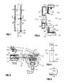
- FIG.1 is a front view of a door according to the invention;
- FIG.2 is an enlarged and somewhat simplified sectional view taken along line 2-2 of FIG.1 and showing the end portions of the door as well as an adjoining frame construction of a switch cabinet;
- FIG.3 is a cross-sectional view taken along line 3-3 in FIG.1;
- FIG.4 is a lateral view of a jacking leg;
- FIG.5 is a top view of the leg shown in FIG.4;
- FIG.6 is an end view of a profile element for the locking side of the door;
- FIG.7 is an end view of a profile element for the hinge side of the door;
- FIG.8 is an end view of a profile element for the hinge side of the cabinet; and
- FIG.9 is an enlarged cross-sectional view of the operative portion of a hinge construction according to the invention.
- The door shown in FIG.1 comprises a
door leaf 10 the one vertival edge of which is connected to ahinge construction 30 and at the other edge connected to alocking construction 70. In its closed position the door is designed to cover an opening 104 (FIG.2 and 3) defined by aframe construction 102 of a switch cabinet generally designed byreference numeral 100 and shown only fragmentarily. - According to the invention, the
locking construction 70 is not mounted in thedoor leaf 10 itself but incorporated in an independent constructional part comprising a profiled orshaped metal element 42, preferably an extruded aluminum profile, extending throughout the height of the door. The profile 72 (FIG.6) has a closedchannel 78 at the outside of the door and anopen channel door leaf 10. Theinner portion 76 of the open channel is intended for receiving a locking bar 90 (described later), and theouter portion 74 of the open channel is used as a recess for receiving the corresponding edge portion 20 (FIG.3) of thedoor leaf 10. A shoulder orflange 86 located between thechannel portions edge portion 20. In the closedchannel 78 of theprofile 72 twoscrew pockets locking bar 90 shown in FIG.3 extends substantially throughout the length of theprofile 70 and is preferably bolted to theprofile 70 by countersunk screws from the inside of the door (not shown). Moreover, in thelocking bar 90 and in the inside flange of the theprofile 72, a plurality of key-hole shaped recesses (one only is shown) are provided spaced along theprofile 72, each recess comprising avertical slot 92 which is downwards widened to acircular hole 94. In the closed position of the door, each key-hole recess corresponding locking member 96 having an enlarged head portion and protruting through anopening 106 from theframe construction 102. The opposite end of eachlocking member 96 is received in arespective bore 110 of a retaining bar 118 and secured thereto by a nut 98 at the threaded end thereof. The retaining bar 108 is in turn preferably bolted by countersunk screws at the front side of theframe construction 102. The opening 106 preferably has an oversize such that the retaining bar 108 and therespective locking members 96 can be adjusted relative the key-hole recesses - According to the invention, the
hinge device 30 is designed as closed profile element hinge consisting of twometal profiles - The door profile 32 (FIG.7) of the
hinge construction 30, has, like theprofile 72 of the locking construction, a closedlongitudinal channel 46 provided at the outside of the door and alongitudinal channel 42 opening to the corresponding edge portion 22 (FIG.3) of thedoor leaf 10 to receive thisedge portion 22. The depth of theopen channel 42 is delimited by astop 56 provided at one side of the channel. Screwpockets channel 46 and theopen channel 42, respectively, for allowing a cover plate indicated in FIG.1 to be screwed onto the top end ofprofile 32. Laterally outside the closedchannel 46, theprofile 32 has ahinge portion 34. - By the fact that the
profiles channels door leaf 10, the profiles are given a good bending and torsional rigidity, whereby they are able to stiffen or strengthen the longitudinal edge portions of the door. The outside ofhinge portion 34 ofprofile 32 together with the outside of the wall portions of closedchannel 46 form a trapezoid ledge or strip that is symmetrical to the trapezoid ledge formed by the outside of the wall portions of thechannel 78 of theprofile 72 at the opposite longitudinal edge of thedoor leaf 10. The door is thereby also rendered an attractive appearance. Thecabinet profile 60 of thehinge construction 30 has a flange 64 (FIG.8) connectable to theframe construction 102, and ahinge portion 62 complementary to thehinge portion 34 of thedoor profile 32. - The
interengaging hinge portions portions spiral portion 34 has an entering subcircular surface A having a large radius R1. The sub-circular inner surface is transformed via a flat surface B to a koaxial sub-circular inner surface C having a small radius R3.Profile 34 then continues by a sub-circular outer surface D being opposite to inner surface C and having an intermediate radius R2, and by a plane outer surface E being opposite to flat inner surface B. The innerspiral portion 62 in turn has a pair of opposite initially sub-circular outer and inner respective surfaces a and d adapted to cooperate with the respective surfaces A and D of theprofile 34 at the radii R1 and R2, an ending sub-circular surface c adapted to cooperate with the surface C of theprofile 34 at the radius R3, and a flat surface b extending between surfaces a and c and adapted to cooperate with the flat surface B ofprofile 34 as an end stop in the closed position of the hinge. As an end stop in the open or swung-up position of the hinge, the inner surface D of theprofile 62 is preceded by a flat surface e adapted to cooperate with the flat surface E ofprofile 34, as indicated by the swung-outprofile 32 shown by phantom lines in FIG.8. By the embodiment shown and described the hinge is given a very sturdy construction having three coaxial pairs of bearing surfaces A-a, C-c and D-d that simultanously are in engagement with each other over substantially the whole operational area of the hinge. The mutually cooperating spiral shapedportions profiles 24 and 62 is enhanced by the pressure generated for example by an electric arc in the cabinet space encased by the door, by virtue of thereby at least some hinge surfaces are pressed against each other. - The
cabinet profile 60 of thehinge construction 30 is in a suitably manner secured to theframe construction 102 by threaded fasteners 112 (FIG.3). In order to facilitate the mounting, theflange 64 of thecabinet profile 60 is provided with a longitudinaldrilling indication groove 68 and a retainingshoulder 66 for locking engagement with the respective faces of the bolt heads of fasteners 112. Corresponding longitudinal drilling indication grooves are also provided at 82 and 52 on theinner flanges 84 and 54 of theprofiles - To facilitate the assembly of the independent functional parts of the door, namely the
profile 72 including thelocking construction 70, thedoor leaf 10, and thedoor profile 32 including one half of thehinge construction 30, theprofiles blind rivets 114 which, after drilling of connection holes through the profiles and theedge portions door leaf 10 and into the closedlongitudinal channels channels - The outer
sheet metal plate 18 of thedoor leaf 10 is shown in FIG.3 folded approximately in the shape of a "J" outside of theisolating material door leaf 10. The isolating material can however also be set into the fold (not shown). The isolating material is preferably the GIBOGI material referred to in the beginning of this description, which material consists of a lamina made of alternating plaster andwood fibre boards sheet steel plate 18 of thedoor leaf 10, and which material is very resistant and isolating against the high temperatures and pressures that are generated for example at an electrical arc discharge in the cabinet. At its inner face the door leaf can be lined by acover plate 12 of a suitable material. - FIGS.3 through 5 show an arrangement for operating the locking and unlocking of the door and including a
lever mechanism 120 and ajacking leg 150. - The
lever mechanism 120 substantially comprise an angled operating handle 122, anhousing 128 and arotatable disk 134 mounted therein. - The angled engagement end of the handle 122 comprises a
cylindrical control portion 124 adapted to be received as a journal bearing in abore 130 in thehousing 128. Opposite thereto within awider bore 132 in thehousing 128 therotatable disk 134 is mounted.Disk 134 has acentral square aperture 136 adapted to receive the engagement end complementary thereto of the angled handle 122 for turning thedisk 134. On thedisk 134 is also provided apin 140 excentrically located and adapted to engage into atransverse slot 152 in the jackingleg 150. Thehousing 128 is set into asub-circular recess 140 at the outer side of thedoor profile 32 and bolted thereto, as indicated in FIG.1. - As is apparent from FIG.1 and FIG.3, the
bar 150 of the jackingleg 150 is extending within the closedlongitudinal channel 46 of theprofile 32 from the vicinity of thelocking mechanism 120 to the lower mouth of thechannel 46 where it is completed by apressure foot 156. A support member 158 (FIG.1) for the bottom face of thefoot 156 is arranged supported by the floor or by the frame construction (not shown). - From the foregoing description it will be apparent that when the handle 122 inserted into the
housing 128 is turned in a counter clockwise direction in FIG.1, the jackingleg 150 will be displaced downwards such that thefoot 156 is brought into engagement with thesupport member 158 and tending to push the door upwards. - Thereby the door will be displaced relative to the
cabinet 100 by longitudinal translation of thehinge portion 34 of the door relative the hinge portion of theframe 62. - When closing the door, the
circular openings 94 of the key-holes are aligned with the lockingmembers 96 so that the heads thereof can engage behind the lockingbar 90 to lock the door when the door again is lowered by turning the handle 122 back to its original position. - In the cross-sectional view according to FIG.2 the upper and lower portions of the
door leaf 10 are shown spaced from theframe construction 102 for clarification. The upper portion of thedoor leaf 10 is terminated by across beam 160 having a downwardly orientedflange 162 adjacent to thecabinet 100. Provided at the lower portion of thedoor leaf 10 is across beam 166 and connected to the top face thereof, for example by welding, is abeam 168 having an L-shaped cross-section, theshorter flange 170 of which extends downwardly at a distance from thecross beam 166. - At the upper edge of the opening of the frame construction 102 a
cross beam 180 is arranged in a similar way and having an upwardly orientedflange 182 spaced at the outside of theopening 104. At the bottom edge ofopening 104 and at a distance from the inside thereof across beam 190 having an upwardly orientedflange 192 is provided. - FIG.2 shows the
door leaf 10 in the raised position. When the door is closed and the door leaf is lowered by the arrangement described previously, theflanges door leaf 10 will be brought into engagement behind theflange 182 of theframe construction 102 and behind the bottom edge of theopening 104. Thereby the door is locked or retained from all sides at theframe construction 102. - In order to prevent issuance of the poisonous gases that can be generated on an electric arc discharge within the
cabinet 100, also sealing means in the shape of angled spring steel leaves, strips orbands frame construction 102, as is apparent from FIG.3 and FIG.4. Thespring steel band 184 provided along the longitudinal top edge of theopening 104, has a bottom edge located behindflange 182 and has its opposite folded-back edge portion inserted into anupper insulation layer 188 for the cabinet and is also retained in place by a screw joint 204. As shown in FIG.2, thespring steel band 200 situated at the bottom edge of opening 104 is adapted to contact the side facing the cabinet of doorleaf cross beam 166 and is in the embodiment shown secured between theframe construction 102 and a base 198 by screw joints 194. The thirdangled steel band 202 is suitably connected, for example bolted, to the outside of theframe construction 102 and at the locking portion thereof. At the corners on the locking side of theframe construction 102, the steel band is overlapped from the outside by thesteel bands 184, 200 (not shown). Thereby a good sealing action is obtained also in the corners of the door opening. - Since the
hinge construction 30 is tight in itself, no further sealing means is required at this side of theframe construction 102. - For additional sealing at the lower edge of the door opening 104 the groove defined between this lower edge and the flange 192 (FIG.2) may be filled by a suitable sealing compound.
Claims (9)
- A door for an electric switch cabinet, comprising a door leaf made of sheet metal and/or any other material isolating from fire and arcs, a hinge construction at a vertical edge of said door leaf and connectable to the cabinet frame, and a locking device cooperating with the frame at the other vertical edge of said door leaf, characterized in that said hinge construction (30) comprises a hinge composed of slidably and pivotably interengaging profile elements (34, 62), that latch means (162, 170) are provided at the upper and lower edges of the door and adapted for engagement with complementary latch means (182, 184) provided at the frame (102), and that a lifting or jacking mechanism (120, 150) is provided for vertically displacing the door via said hinge to bring said latch means (162, 170, 182, 104) and said complementary latch means into and out of engagement relative each other.
- A door according to claim 1 characterized in that the locking device and the hinge construction are provided on separate profile elements (72, 32, 60) which can be mounted to the vertical edges of the door leaf (10).
- A door according to claim 2 characterized in that the jacking mechanism comprises a jacking leg (150) engagable with a support (bearing 158) which leg is slidably guided in a channel (46) of the profile element (32) of the hinge construction.
- A door according to claim 3 characterized in that the jacking mechanism comprises an operating disk (134) rotatatbly mounted to the profile element (32) of the hinge construction, said disk having an excentrically located pin (138) for engagement into a transversely extending slot (152) in the jacking leg (150).
- A door according to claim 1 characterized in that the latch means comprise vertical flange elements (162, 170, 182) of cross beams (160, 168, 180) provided in the door leaf (10) and in the frame (102).
- A door leaf according to claim 1 characterized in that elongated leaf spring elements (184, 200, 202) are provided on the frame (102) for sealing engagement with the inner face of the door leaf (10) in the closed position of the door.
- A door according to claim 1 characterized in that the profile element hinge comprises a pair of mutually pivotable portions (34; 62) which are insertable into each other and each of which has three coaxial, radially separated pivot bearing surfaces (A, C, D and a, c, d).
- A door according to claim 7 characterized in that one (34) of said portions comprises an introductory sub-circular inner surface (A) having a first radius (R1), a terminating sub-circular outer surface (D) having a second radius (R2) which is smaller than the first radius (R1) and a terminating sub-circular inner surface (C) having a third radius (R3) which is smaller than the second radius (R2), and wherein the other (62) of said portions comprises an introductory sub-circular outer surface (a) having a radius corresponding to the first radius (R1), an introductory sub-circular inner surface (d) having a radius corresponding to the second radius (R2) and a terminating sub-circular outer surface (c) having a radius corresponding to the third radius (R3).
- A door according to claim 8, characterized in that said one portion (34) comprises a section confined by flat surfaces (B, E) between said introductory inner surface (A) and said terminating inner and outer surfaces (C, D), and wherein said other portion (62) comprises a flat surface (e) adjoining the introductory inner surface (d) and a flat surface (b) between the introductory outer surface and the terminating outer surface (c).
Applications Claiming Priority (2)
| Application Number | Priority Date | Filing Date | Title |
|---|---|---|---|
| SE9000768 | 1990-03-05 | ||
| SE9000768A SE500606C2 (en) | 1990-03-05 | 1990-03-05 | Door for switchgear cabinet |
Publications (2)
| Publication Number | Publication Date |
|---|---|
| EP0447381A1 true EP0447381A1 (en) | 1991-09-18 |
| EP0447381B1 EP0447381B1 (en) | 1994-05-11 |
Family
ID=20378762
Family Applications (1)
| Application Number | Title | Priority Date | Filing Date |
|---|---|---|---|
| EP91850039A Expired - Lifetime EP0447381B1 (en) | 1990-03-05 | 1991-02-18 | Door for an electric switch cabinet |
Country Status (8)
| Country | Link |
|---|---|
| US (1) | US5207023A (en) |
| EP (1) | EP0447381B1 (en) |
| CA (1) | CA2036594A1 (en) |
| DE (1) | DE69101943T2 (en) |
| DK (1) | DK0447381T3 (en) |
| FI (1) | FI95312C (en) |
| NO (1) | NO178042C (en) |
| SE (1) | SE500606C2 (en) |
Cited By (6)
| Publication number | Priority date | Publication date | Assignee | Title |
|---|---|---|---|---|
| DE9411662U1 (en) * | 1994-07-19 | 1994-10-06 | Reinshagen Kabelwerk Gmbh | Cuboid housing |
| GB2301229A (en) * | 1995-05-23 | 1996-11-27 | Gen Electric | Housing for motor controller with slidable, insulated doors |
| US5654871A (en) * | 1995-12-11 | 1997-08-05 | General Electric Company | Motor control center providing phase conductor access |
| WO2006040677A1 (en) * | 2004-10-13 | 2006-04-20 | Roberto Celli | Plasterboard panel for access to a compartment and method for making a plasterboard panel for access to a compartment |
| GB2472762A (en) * | 2009-06-01 | 2011-02-23 | Glasdon Ltd | Waste container with access door |
| FR2996371A1 (en) * | 2012-09-28 | 2014-04-04 | Legrand France | Hinge for door of wall box, has two complementary hollow windings, and solid shaft, where one of windings extends over angular extent exceeding specific degrees so that windings extend angularly within itself |
Families Citing this family (3)
| Publication number | Priority date | Publication date | Assignee | Title |
|---|---|---|---|---|
| DE4311246C1 (en) * | 1993-04-06 | 1994-03-31 | Schroff Gmbh | Housing for electronic equipment with HF sealing - provided by formed leaf spring contact clips that are located of ribs of frame bars and engage fill in panels |
| US20070256363A1 (en) * | 2005-11-10 | 2007-11-08 | York International Corporation | Access door |
| US11146044B2 (en) * | 2018-07-13 | 2021-10-12 | Abb Schweiz Ag | Filler plate, loadcenter and method for covering an opening in a deadfront of a loadcenter |
Citations (3)
| Publication number | Priority date | Publication date | Assignee | Title |
|---|---|---|---|---|
| BE641865A (en) * | ||||
| CH302008A (en) * | 1949-10-08 | 1954-09-30 | Gretsch Unitas Gmbh | Door and window sash lifting device. |
| GB1347492A (en) * | 1972-02-04 | 1974-02-27 | Hardall Ltd | Window assemblies |
Family Cites Families (10)
| Publication number | Priority date | Publication date | Assignee | Title |
|---|---|---|---|---|
| US1518613A (en) * | 1922-05-22 | 1924-12-09 | Reuben B Teeter | Casement window |
| US1529524A (en) * | 1923-03-30 | 1925-03-10 | Frederick H Wilbur | Door-lifting device |
| US1895572A (en) * | 1931-03-16 | 1933-01-31 | Motor Products Corp | Hinge |
| US2069237A (en) * | 1934-09-15 | 1937-02-02 | Motor Terminals Co | Door operating mechanism |
| US2662766A (en) * | 1951-09-12 | 1953-12-15 | Lawrence O Burress | Window opening and closing mechanism |
| US2717064A (en) * | 1952-10-06 | 1955-09-06 | Lester R Hock | Door latching apparatus |
| US3139958A (en) * | 1960-12-20 | 1964-07-07 | Witt Clarence Neil De | Portable foldable building structure |
| SE320586B (en) * | 1967-11-13 | 1970-02-09 | Bofors Ab | |
| US3820282A (en) * | 1972-11-24 | 1974-06-28 | Kornylac Co | Hydraulic door hinge |
| US4756123A (en) * | 1986-11-25 | 1988-07-12 | American Sterilizer Company | Chamber door |
-
1990
- 1990-03-05 SE SE9000768A patent/SE500606C2/en unknown
-
1991
- 1991-02-18 DE DE69101943T patent/DE69101943T2/en not_active Expired - Fee Related
- 1991-02-18 DK DK91850039.8T patent/DK0447381T3/en active
- 1991-02-18 EP EP91850039A patent/EP0447381B1/en not_active Expired - Lifetime
- 1991-02-19 CA CA002036594A patent/CA2036594A1/en not_active Abandoned
- 1991-02-25 US US07/660,413 patent/US5207023A/en not_active Expired - Fee Related
- 1991-02-26 NO NO910749A patent/NO178042C/en unknown
- 1991-02-28 FI FI910998A patent/FI95312C/en active
Patent Citations (3)
| Publication number | Priority date | Publication date | Assignee | Title |
|---|---|---|---|---|
| BE641865A (en) * | ||||
| CH302008A (en) * | 1949-10-08 | 1954-09-30 | Gretsch Unitas Gmbh | Door and window sash lifting device. |
| GB1347492A (en) * | 1972-02-04 | 1974-02-27 | Hardall Ltd | Window assemblies |
Cited By (8)
| Publication number | Priority date | Publication date | Assignee | Title |
|---|---|---|---|---|
| DE9411662U1 (en) * | 1994-07-19 | 1994-10-06 | Reinshagen Kabelwerk Gmbh | Cuboid housing |
| GB2301229A (en) * | 1995-05-23 | 1996-11-27 | Gen Electric | Housing for motor controller with slidable, insulated doors |
| GB2301229B (en) * | 1995-05-23 | 1999-08-25 | Gen Electric | Motor control center |
| US5654871A (en) * | 1995-12-11 | 1997-08-05 | General Electric Company | Motor control center providing phase conductor access |
| WO2006040677A1 (en) * | 2004-10-13 | 2006-04-20 | Roberto Celli | Plasterboard panel for access to a compartment and method for making a plasterboard panel for access to a compartment |
| GB2472762A (en) * | 2009-06-01 | 2011-02-23 | Glasdon Ltd | Waste container with access door |
| GB2472762B (en) * | 2009-06-01 | 2013-12-18 | Glasdon Uk Ltd | Container |
| FR2996371A1 (en) * | 2012-09-28 | 2014-04-04 | Legrand France | Hinge for door of wall box, has two complementary hollow windings, and solid shaft, where one of windings extends over angular extent exceeding specific degrees so that windings extend angularly within itself |
Also Published As
| Publication number | Publication date |
|---|---|
| SE9000768L (en) | 1991-09-06 |
| DE69101943T2 (en) | 1994-08-18 |
| FI910998A (en) | 1991-09-06 |
| NO910749L (en) | 1991-09-06 |
| SE500606C2 (en) | 1994-07-25 |
| FI910998A0 (en) | 1991-02-28 |
| NO910749D0 (en) | 1991-02-26 |
| SE9000768D0 (en) | 1990-03-05 |
| NO178042B (en) | 1995-10-02 |
| FI95312B (en) | 1995-09-29 |
| EP0447381B1 (en) | 1994-05-11 |
| US5207023A (en) | 1993-05-04 |
| NO178042C (en) | 1996-01-10 |
| DE69101943D1 (en) | 1994-06-16 |
| DK0447381T3 (en) | 1994-06-13 |
| FI95312C (en) | 1996-01-10 |
| CA2036594A1 (en) | 1991-09-06 |
Similar Documents
| Publication | Publication Date | Title |
|---|---|---|
| US5351442A (en) | Door closure for refrigeration housing | |
| US5816017A (en) | Fire retardant door and exit device for same | |
| EP0785334B2 (en) | Fire-resistant structural member | |
| EP0447381B1 (en) | Door for an electric switch cabinet | |
| US5819834A (en) | Door assembly with improved support system | |
| US4431044A (en) | Security closure apparatus for buildings | |
| US4861082A (en) | Door security system | |
| KR20050060035A (en) | Security door and frame construction | |
| US5549148A (en) | Blade for accordion storm shutter | |
| US5477903A (en) | Accordion storm shutter | |
| US4520736A (en) | Lightweight safe and door mechanism therefor | |
| EP0332648A1 (en) | Joining of side-plates at a metal door. | |
| US5016949A (en) | Swing door and door frame assembly | |
| US4888918A (en) | Fire-resistant door | |
| US5074606A (en) | Door security system | |
| GB2045908A (en) | Refrigerator or like casings | |
| EP0803634B1 (en) | Glazed fire door | |
| US4188753A (en) | Door arrangement, especially for a residential structure | |
| DE4423944A1 (en) | Door or window | |
| WO1989004907A1 (en) | Protection device for a window or door | |
| EP1375805B1 (en) | Acces door for sectional gates, with interchangeable sections | |
| US10961744B2 (en) | Door latching system having a reduced profile exit device | |
| EP0666402B1 (en) | Sectional door | |
| EP1298270B1 (en) | Pivotable shutter panel assembly | |
| DE3621419C2 (en) |
Legal Events
| Date | Code | Title | Description |
|---|---|---|---|
| PUAI | Public reference made under article 153(3) epc to a published international application that has entered the european phase |
Free format text: ORIGINAL CODE: 0009012 |
|
| AK | Designated contracting states |
Kind code of ref document: A1 Designated state(s): DE DK FR GB |
|
| 17P | Request for examination filed |
Effective date: 19911021 |
|
| 17Q | First examination report despatched |
Effective date: 19930408 |
|
| RAP1 | Party data changed (applicant data changed or rights of an application transferred) |
Owner name: STOHNE KRAFTTEKNIK AB |
|
| GRAA | (expected) grant |
Free format text: ORIGINAL CODE: 0009210 |
|
| AK | Designated contracting states |
Kind code of ref document: B1 Designated state(s): DE DK FR GB |
|
| REG | Reference to a national code |
Ref country code: DK Ref legal event code: T3 |
|
| REF | Corresponds to: |
Ref document number: 69101943 Country of ref document: DE Date of ref document: 19940616 |
|
| ET | Fr: translation filed | ||
| PLBE | No opposition filed within time limit |
Free format text: ORIGINAL CODE: 0009261 |
|
| STAA | Information on the status of an ep patent application or granted ep patent |
Free format text: STATUS: NO OPPOSITION FILED WITHIN TIME LIMIT |
|
| 26N | No opposition filed | ||
| PGFP | Annual fee paid to national office [announced via postgrant information from national office to epo] |
Ref country code: GB Payment date: 19990127 Year of fee payment: 9 |
|
| PGFP | Annual fee paid to national office [announced via postgrant information from national office to epo] |
Ref country code: DE Payment date: 19990129 Year of fee payment: 9 |
|
| PGFP | Annual fee paid to national office [announced via postgrant information from national office to epo] |
Ref country code: FR Payment date: 19990210 Year of fee payment: 9 |
|
| PGFP | Annual fee paid to national office [announced via postgrant information from national office to epo] |
Ref country code: DK Payment date: 19990217 Year of fee payment: 9 |
|
| PG25 | Lapsed in a contracting state [announced via postgrant information from national office to epo] |
Ref country code: GB Free format text: LAPSE BECAUSE OF NON-PAYMENT OF DUE FEES Effective date: 20000218 Ref country code: DK Free format text: LAPSE BECAUSE OF NON-PAYMENT OF DUE FEES Effective date: 20000218 |
|
| GBPC | Gb: european patent ceased through non-payment of renewal fee |
Effective date: 20000218 |
|
| PG25 | Lapsed in a contracting state [announced via postgrant information from national office to epo] |
Ref country code: FR Free format text: LAPSE BECAUSE OF NON-PAYMENT OF DUE FEES Effective date: 20001031 |
|
| PG25 | Lapsed in a contracting state [announced via postgrant information from national office to epo] |
Ref country code: DE Free format text: LAPSE BECAUSE OF NON-PAYMENT OF DUE FEES Effective date: 20001201 |
|
| REG | Reference to a national code |
Ref country code: FR Ref legal event code: ST |
|
| REG | Reference to a national code |
Ref country code: DK Ref legal event code: EBP |