EP0446930B1 - Pyrolitisches Konvertierungssystem - Google Patents
Pyrolitisches Konvertierungssystem Download PDFInfo
- Publication number
- EP0446930B1 EP0446930B1 EP91103962A EP91103962A EP0446930B1 EP 0446930 B1 EP0446930 B1 EP 0446930B1 EP 91103962 A EP91103962 A EP 91103962A EP 91103962 A EP91103962 A EP 91103962A EP 0446930 B1 EP0446930 B1 EP 0446930B1
- Authority
- EP
- European Patent Office
- Prior art keywords
- drum
- converter
- converter drum
- chamber
- tube
- Prior art date
- Legal status (The legal status is an assumption and is not a legal conclusion. Google has not performed a legal analysis and makes no representation as to the accuracy of the status listed.)
- Expired - Lifetime
Links
- 238000006243 chemical reaction Methods 0.000 title claims abstract description 21
- 239000007789 gas Substances 0.000 claims abstract description 51
- XLYOFNOQVPJJNP-UHFFFAOYSA-N water Substances O XLYOFNOQVPJJNP-UHFFFAOYSA-N 0.000 claims abstract description 50
- 239000000463 material Substances 0.000 claims abstract description 29
- 239000000047 product Substances 0.000 claims abstract description 24
- 229930195733 hydrocarbon Natural products 0.000 claims abstract description 13
- 150000002430 hydrocarbons Chemical class 0.000 claims abstract description 13
- 239000012265 solid product Substances 0.000 claims abstract description 12
- 239000007788 liquid Substances 0.000 claims abstract description 9
- 239000007787 solid Substances 0.000 claims abstract description 6
- 238000004140 cleaning Methods 0.000 claims abstract description 4
- 238000002485 combustion reaction Methods 0.000 claims abstract description 4
- 239000011159 matrix material Substances 0.000 claims abstract 2
- 239000012530 fluid Substances 0.000 claims description 12
- 238000010438 heat treatment Methods 0.000 claims description 8
- 239000004215 Carbon black (E152) Substances 0.000 claims description 7
- 239000002245 particle Substances 0.000 claims description 4
- OYPRJOBELJOOCE-UHFFFAOYSA-N Calcium Chemical compound [Ca] OYPRJOBELJOOCE-UHFFFAOYSA-N 0.000 claims description 3
- 239000011575 calcium Substances 0.000 claims description 3
- 229910052791 calcium Inorganic materials 0.000 claims description 3
- 238000004891 communication Methods 0.000 claims description 3
- 238000007599 discharging Methods 0.000 claims description 3
- 206010022000 influenza Diseases 0.000 claims description 2
- 230000003028 elevating effect Effects 0.000 claims 3
- 238000009833 condensation Methods 0.000 claims 1
- 230000005494 condensation Effects 0.000 claims 1
- 230000008602 contraction Effects 0.000 claims 1
- 238000009413 insulation Methods 0.000 claims 1
- 238000007790 scraping Methods 0.000 claims 1
- 239000011343 solid material Substances 0.000 claims 1
- 238000000197 pyrolysis Methods 0.000 abstract description 27
- 238000002347 injection Methods 0.000 abstract description 7
- 239000007924 injection Substances 0.000 abstract description 7
- 235000008733 Citrus aurantifolia Nutrition 0.000 abstract description 5
- 235000011941 Tilia x europaea Nutrition 0.000 abstract description 5
- 239000004571 lime Substances 0.000 abstract description 5
- 229920003023 plastic Polymers 0.000 abstract description 5
- 239000004033 plastic Substances 0.000 abstract description 5
- 239000006229 carbon black Substances 0.000 abstract description 4
- 150000008280 chlorinated hydrocarbons Chemical class 0.000 abstract description 3
- 238000002844 melting Methods 0.000 abstract description 3
- 230000008018 melting Effects 0.000 abstract description 3
- 229910052751 metal Inorganic materials 0.000 abstract description 3
- 239000002184 metal Substances 0.000 abstract description 3
- 239000010426 asphalt Substances 0.000 abstract description 2
- 239000003245 coal Substances 0.000 abstract description 2
- 235000013410 fast food Nutrition 0.000 abstract description 2
- 230000005484 gravity Effects 0.000 abstract description 2
- 150000002739 metals Chemical class 0.000 abstract description 2
- 239000010813 municipal solid waste Substances 0.000 abstract description 2
- 239000004058 oil shale Substances 0.000 abstract description 2
- 239000011368 organic material Substances 0.000 abstract description 2
- 239000013502 plastic waste Substances 0.000 abstract description 2
- 239000010801 sewage sludge Substances 0.000 abstract description 2
- 229920006328 Styrofoam Polymers 0.000 abstract 1
- 230000006378 damage Effects 0.000 abstract 1
- 239000003546 flue gas Substances 0.000 abstract 1
- 239000010985 leather Substances 0.000 abstract 1
- 239000008261 styrofoam Substances 0.000 abstract 1
- 125000006850 spacer group Chemical group 0.000 description 10
- 239000003921 oil Substances 0.000 description 9
- QGZKDVFQNNGYKY-UHFFFAOYSA-N Ammonia Chemical compound N QGZKDVFQNNGYKY-UHFFFAOYSA-N 0.000 description 6
- ATUOYWHBWRKTHZ-UHFFFAOYSA-N Propane Chemical compound CCC ATUOYWHBWRKTHZ-UHFFFAOYSA-N 0.000 description 6
- UXVMQQNJUSDDNG-UHFFFAOYSA-L Calcium chloride Chemical compound [Cl-].[Cl-].[Ca+2] UXVMQQNJUSDDNG-UHFFFAOYSA-L 0.000 description 4
- ZAMOUSCENKQFHK-UHFFFAOYSA-N Chlorine atom Chemical compound [Cl] ZAMOUSCENKQFHK-UHFFFAOYSA-N 0.000 description 4
- 230000000712 assembly Effects 0.000 description 4
- 238000000429 assembly Methods 0.000 description 4
- 229910001628 calcium chloride Inorganic materials 0.000 description 4
- 239000001110 calcium chloride Substances 0.000 description 4
- 239000000460 chlorine Substances 0.000 description 4
- 229910052801 chlorine Inorganic materials 0.000 description 4
- 238000013461 design Methods 0.000 description 4
- 239000012535 impurity Substances 0.000 description 4
- VNWKTOKETHGBQD-UHFFFAOYSA-N methane Chemical compound C VNWKTOKETHGBQD-UHFFFAOYSA-N 0.000 description 4
- 238000000034 method Methods 0.000 description 4
- 150000003071 polychlorinated biphenyls Chemical class 0.000 description 4
- NINIDFKCEFEMDL-UHFFFAOYSA-N Sulfur Chemical compound [S] NINIDFKCEFEMDL-UHFFFAOYSA-N 0.000 description 3
- 229910021529 ammonia Inorganic materials 0.000 description 3
- 239000000567 combustion gas Substances 0.000 description 3
- 239000000295 fuel oil Substances 0.000 description 3
- 238000012986 modification Methods 0.000 description 3
- 230000004048 modification Effects 0.000 description 3
- 238000012856 packing Methods 0.000 description 3
- 230000008569 process Effects 0.000 description 3
- 238000012545 processing Methods 0.000 description 3
- 239000001294 propane Substances 0.000 description 3
- 210000004894 snout Anatomy 0.000 description 3
- 239000011593 sulfur Substances 0.000 description 3
- 229910052717 sulfur Inorganic materials 0.000 description 3
- 239000003039 volatile agent Substances 0.000 description 3
- OKTJSMMVPCPJKN-UHFFFAOYSA-N Carbon Chemical compound [C] OKTJSMMVPCPJKN-UHFFFAOYSA-N 0.000 description 2
- CWYNVVGOOAEACU-UHFFFAOYSA-N Fe2+ Chemical compound [Fe+2] CWYNVVGOOAEACU-UHFFFAOYSA-N 0.000 description 2
- 239000002956 ash Substances 0.000 description 2
- 229910052799 carbon Inorganic materials 0.000 description 2
- 210000004907 gland Anatomy 0.000 description 2
- 239000011810 insulating material Substances 0.000 description 2
- 239000011490 mineral wool Substances 0.000 description 2
- 239000000203 mixture Substances 0.000 description 2
- 238000010926 purge Methods 0.000 description 2
- 230000000284 resting effect Effects 0.000 description 2
- 238000000926 separation method Methods 0.000 description 2
- 238000003860 storage Methods 0.000 description 2
- 238000012546 transfer Methods 0.000 description 2
- 125000000391 vinyl group Chemical group [H]C([*])=C([H])[H] 0.000 description 2
- 229920002554 vinyl polymer Polymers 0.000 description 2
- 230000002411 adverse Effects 0.000 description 1
- 230000003190 augmentative effect Effects 0.000 description 1
- 230000015572 biosynthetic process Effects 0.000 description 1
- 239000003153 chemical reaction reagent Substances 0.000 description 1
- 238000001816 cooling Methods 0.000 description 1
- 230000003247 decreasing effect Effects 0.000 description 1
- 238000010586 diagram Methods 0.000 description 1
- 238000006073 displacement reaction Methods 0.000 description 1
- 230000009977 dual effect Effects 0.000 description 1
- 210000005069 ears Anatomy 0.000 description 1
- 230000000694 effects Effects 0.000 description 1
- 230000007613 environmental effect Effects 0.000 description 1
- 239000002360 explosive Substances 0.000 description 1
- -1 ferrous metals Chemical class 0.000 description 1
- 238000010304 firing Methods 0.000 description 1
- 238000007667 floating Methods 0.000 description 1
- 239000011261 inert gas Substances 0.000 description 1
- 229910010272 inorganic material Inorganic materials 0.000 description 1
- 239000011147 inorganic material Substances 0.000 description 1
- 238000012423 maintenance Methods 0.000 description 1
- 239000003208 petroleum Substances 0.000 description 1
- 238000002360 preparation method Methods 0.000 description 1
- 238000010298 pulverizing process Methods 0.000 description 1
- 230000003134 recirculating effect Effects 0.000 description 1
- 230000009467 reduction Effects 0.000 description 1
- 238000007670 refining Methods 0.000 description 1
- 238000005201 scrubbing Methods 0.000 description 1
- 238000007789 sealing Methods 0.000 description 1
- 239000000243 solution Substances 0.000 description 1
- 229910001220 stainless steel Inorganic materials 0.000 description 1
- 239000010935 stainless steel Substances 0.000 description 1
- 239000000725 suspension Substances 0.000 description 1
- 230000032258 transport Effects 0.000 description 1
- 238000011144 upstream manufacturing Methods 0.000 description 1
- 239000002699 waste material Substances 0.000 description 1
Images


Classifications
-
- C—CHEMISTRY; METALLURGY
- C10—PETROLEUM, GAS OR COKE INDUSTRIES; TECHNICAL GASES CONTAINING CARBON MONOXIDE; FUELS; LUBRICANTS; PEAT
- C10B—DESTRUCTIVE DISTILLATION OF CARBONACEOUS MATERIALS FOR PRODUCTION OF GAS, COKE, TAR, OR SIMILAR MATERIALS
- C10B53/00—Destructive distillation, specially adapted for particular solid raw materials or solid raw materials in special form
- C10B53/07—Destructive distillation, specially adapted for particular solid raw materials or solid raw materials in special form of solid raw materials consisting of synthetic polymeric materials, e.g. tyres
-
- C—CHEMISTRY; METALLURGY
- C10—PETROLEUM, GAS OR COKE INDUSTRIES; TECHNICAL GASES CONTAINING CARBON MONOXIDE; FUELS; LUBRICANTS; PEAT
- C10B—DESTRUCTIVE DISTILLATION OF CARBONACEOUS MATERIALS FOR PRODUCTION OF GAS, COKE, TAR, OR SIMILAR MATERIALS
- C10B1/00—Retorts
- C10B1/10—Rotary retorts
-
- C—CHEMISTRY; METALLURGY
- C10—PETROLEUM, GAS OR COKE INDUSTRIES; TECHNICAL GASES CONTAINING CARBON MONOXIDE; FUELS; LUBRICANTS; PEAT
- C10B—DESTRUCTIVE DISTILLATION OF CARBONACEOUS MATERIALS FOR PRODUCTION OF GAS, COKE, TAR, OR SIMILAR MATERIALS
- C10B49/00—Destructive distillation of solid carbonaceous materials by direct heating with heat-carrying agents including the partial combustion of the solid material to be treated
- C10B49/02—Destructive distillation of solid carbonaceous materials by direct heating with heat-carrying agents including the partial combustion of the solid material to be treated with hot gases or vapours, e.g. hot gases obtained by partial combustion of the charge
- C10B49/04—Destructive distillation of solid carbonaceous materials by direct heating with heat-carrying agents including the partial combustion of the solid material to be treated with hot gases or vapours, e.g. hot gases obtained by partial combustion of the charge while moving the solid material to be treated
-
- C—CHEMISTRY; METALLURGY
- C10—PETROLEUM, GAS OR COKE INDUSTRIES; TECHNICAL GASES CONTAINING CARBON MONOXIDE; FUELS; LUBRICANTS; PEAT
- C10B—DESTRUCTIVE DISTILLATION OF CARBONACEOUS MATERIALS FOR PRODUCTION OF GAS, COKE, TAR, OR SIMILAR MATERIALS
- C10B53/00—Destructive distillation, specially adapted for particular solid raw materials or solid raw materials in special form
-
- F—MECHANICAL ENGINEERING; LIGHTING; HEATING; WEAPONS; BLASTING
- F27—FURNACES; KILNS; OVENS; RETORTS
- F27B—FURNACES, KILNS, OVENS OR RETORTS IN GENERAL; OPEN SINTERING OR LIKE APPARATUS
- F27B7/00—Rotary-drum furnaces, i.e. horizontal or slightly inclined
-
- F—MECHANICAL ENGINEERING; LIGHTING; HEATING; WEAPONS; BLASTING
- F27—FURNACES; KILNS; OVENS; RETORTS
- F27B—FURNACES, KILNS, OVENS OR RETORTS IN GENERAL; OPEN SINTERING OR LIKE APPARATUS
- F27B7/00—Rotary-drum furnaces, i.e. horizontal or slightly inclined
- F27B7/08—Rotary-drum furnaces, i.e. horizontal or slightly inclined externally heated
-
- F—MECHANICAL ENGINEERING; LIGHTING; HEATING; WEAPONS; BLASTING
- F27—FURNACES; KILNS; OVENS; RETORTS
- F27B—FURNACES, KILNS, OVENS OR RETORTS IN GENERAL; OPEN SINTERING OR LIKE APPARATUS
- F27B7/00—Rotary-drum furnaces, i.e. horizontal or slightly inclined
- F27B7/20—Details, accessories or equipment specially adapted for rotary-drum furnaces
- F27B7/32—Arrangement of devices for charging
-
- Y—GENERAL TAGGING OF NEW TECHNOLOGICAL DEVELOPMENTS; GENERAL TAGGING OF CROSS-SECTIONAL TECHNOLOGIES SPANNING OVER SEVERAL SECTIONS OF THE IPC; TECHNICAL SUBJECTS COVERED BY FORMER USPC CROSS-REFERENCE ART COLLECTIONS [XRACs] AND DIGESTS
- Y02—TECHNOLOGIES OR APPLICATIONS FOR MITIGATION OR ADAPTATION AGAINST CLIMATE CHANGE
- Y02E—REDUCTION OF GREENHOUSE GAS [GHG] EMISSIONS, RELATED TO ENERGY GENERATION, TRANSMISSION OR DISTRIBUTION
- Y02E50/00—Technologies for the production of fuel of non-fossil origin
- Y02E50/30—Fuel from waste, e.g. synthetic alcohol or diesel
-
- Y—GENERAL TAGGING OF NEW TECHNOLOGICAL DEVELOPMENTS; GENERAL TAGGING OF CROSS-SECTIONAL TECHNOLOGIES SPANNING OVER SEVERAL SECTIONS OF THE IPC; TECHNICAL SUBJECTS COVERED BY FORMER USPC CROSS-REFERENCE ART COLLECTIONS [XRACs] AND DIGESTS
- Y02—TECHNOLOGIES OR APPLICATIONS FOR MITIGATION OR ADAPTATION AGAINST CLIMATE CHANGE
- Y02P—CLIMATE CHANGE MITIGATION TECHNOLOGIES IN THE PRODUCTION OR PROCESSING OF GOODS
- Y02P20/00—Technologies relating to chemical industry
- Y02P20/141—Feedstock
- Y02P20/143—Feedstock the feedstock being recycled material, e.g. plastics
Definitions
- the present invention relates to pyrolysis conversion systems (methods and apparatus), and particularly to systems utilizing rotary drum pyrolytic converters.
- the invention is especially suitable for use in the pyrolytic conversion of solid hydrocarbons into gases, liquid hydrocarbons and char by the pyrolysis of various feed stocks, such as the tires and plastic waste resulting from shredding of junked automobiles.
- the system is also adapted for pyrolyzing other waste, such plastic containers and trays from fast food restaurants, garbage, sewage sludge, coal, oil shale, broken asphalt and the like which may be comminuted and mixed to provide the feed stock for the converters of the system.
- Pyrolytic converters as have heretofore been provided have required conveyers, augers, or carts for moving the materials to be pyrolyzed through the converter.
- Practical and reliable operation of pyrolysis converters has not been obtained because such devices must operate at high temperatures, for example, exceeding 538°C (1,000°F).
- the material to be processed and the products of pyrolysis, solids, liquids and gases must be introduced and discharged without adversely affecting the integrity of the converter, so that air cannot enter the converter and interfere with the pyrolysis process or engender dangerous, explosive conditions.
- DE-A-28 10 838 shows a pyrolytic conversion system for hydrocarbon containing materials, said system comprising a converter drum having opposite ends, a first of which may be elevated above a second of which, said drum having an axis of rotation about which said converter drum is rotatable, an outer stationary drum disposed around said converter drum, a casing disposed around said outer drum defining an oven chamber and means for heating that oven chamber to maintain the converter drum at a temperature sufficient to pyrolyse said material.
- the solution of the foregoing problems without introducing complexities in design and operation which would affect the reliability and maintainability of the system is the principal feature of the invention.
- the invention also addresses the need for flexibility in the capacity of the system and makes it possible to increase the capacity of the system without extensive modifications.
- a pyrolytic conversion system in accordance with the invention handles solid hydrocarbon containing materials. It utilizes an open converter drum having opposite ends; the first of which is elevated above the second. The drum also has an axis of rotation about which it is rotatable. There is an outer stationary drum disposed around the open converter drum. This stationary drum defines a chamber (which is maintained substantially air-tight) within which the converter drum is disposed. A casing is disposed around the outer drum and defines an oven chamber. Means are provided for heating the oven chamber to maintain the converter drum at a temperature sufficient to pyrolyze materials of interest.
- Means are provided which are in communication with the chamber formed by the outer drum, which are located near the first end of the converter drum, for extracting product gases of pyrolyzation.
- Other means are disposed in essentially airtight relationship with the chamber formed by the outer drum, which are located near the second end of the converter drum, for the discharge of the solid products of pyrolyzation.
- Means are provided which extend through the chamber formed by the outer drum for injecting the materials to be treated into the first end of the converter drum while essentially excluding air from the chamber formed by the stationary drum. Hot gases flow through the oven chamber and are transferred, through the chamber formed by the outer drum, to the converter drum.
- the hydrocarbon materials are motivated by gravity and the rotation of the converter drum and move as they are being pyrolyzed from the first end to the second end where the solid products of pyrolyzation are discharged, while the gaseous and volatile products are extracted near the first end of the converter drum.
- No conveyers, augers or other transports are used within the converter drum.
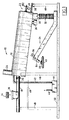
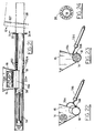
- FIGS. 1-4 there is shown a pyrolytic converter system 10 having a single pyrolytic converter 12.
- a plurality of such converters may be operated in parallel in an expanded system when greater capacity for handling more feedstocks within a given period of time is required.
- An expanded system is shown schematically in FIG. 39 and will be described hereinafter.
- the size of the converter 12 and other components of the system 10 also depends upon the desired feedstock handling capacity of the system.
- a small scale or pilot system may utilize a converter 12 which is about 655 cm (21.5 feet) long and about 97 cm (38 inches) in diameter across the outside thereof.
- a full scale system may typically have a converter 12, 1220 cm (40 feet) long and of a outer diameter of about 290 cm (114 inches). All such dimensions are typical and approximate. It will be appreciated that the system may be scaled to meet specified capacity and other operating and performance requirements.
- the feedstocks are prepared in a storage and preparation section of the system 10 which is not shown in the drawings.
- Conventional shredders, mixers and balers may be used to form the feedstock into comminuted pieces.
- the system preferably uses mixtures of different types of materials for its feedstocks. Each type which is mixed has a different melting point. This mixture of materials with different melting points facilitates smooth movement of the feedstock through the converter 12 without clogging and gumming thereof, as pyrolysis proceeds.
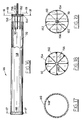
- the drawings show a typical bale 14. These bales are cylindrical and approximately the same diameter as an injection tube 18, which is part of the apparatus for introducing the feedstock into the converter 12. Another part of the introduction apparatus is a hopper 16. In a pilot system, the bales may be approximately 20 cm (8 inches) in diameter and 50 cm (20 inches) long. A typical full scale system may utilize bales 91 cm (36 inches) in diameter and 122 cm (48 inches) long.
- the injection tube 18 may be 152 to 213 cm (five to seven feet) long from the hopper 16 to the end thereof which is located inside the converter 12.
- the tube 18 may be made in sections connected by flanges 20.
- the section of the tube 58 which enters the converter 12 ( see FIG. 4) may be of a material which is different from the rest of the tube 18 and which is more resistant to heat.
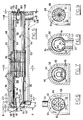
- the converter 12 has a rotatable inner drum 66 in which pyrolysis occurs.
- the inner drum 66 is a stationary, non-rotating outer drum 68.
- This outer drum is closed at its ends by bulkheads 157 and 158 which define an essentially air-tight chamber around the rotating inner drum 66.
- the inner drum is rotated by a drive shaft assembly 22 having a sprocket 182 which is driven by an electric motor through a gear box 183, an output sprocket 187 from the gear box and an endless chain 185.
- the motor may be a one horse power (for a pilot, small size converter) to ten horse power for a typical full scale converter.
- the output RPM may be approximately 1,800 and the gear reduction in the box 183 may be 900 to one or 1,800 to one.
- the drive shaft (102, FIG. 20) of the assembly 22 may be 6 cm (2.375 inches) in diameter for the small scale converter to 52 cm (4.5 inches) in diameter for the full scale converter.
- the drive shaft assembly is water cooled and is described in greater detail in connection with FIG. 20.
- the outer drum 68 is surrounded by a casing generally indicated by reference numeral 52 and shown in greater detail in FIGS. 15 and 15A.
- This casing defines an oven chamber around the outer drum through which combustion gases from a burner heat source 26 circulate.
- the burner 26 is preferably a forced air type where combustion air is fed through burners which burn product gases of pyrolysis during continuous operation of the converter 12. Thus, the hot gases circulate through the oven chamber under pressure. On startup, other heating gases such as propane may be used.
- the product gases of pyrolysis may be stored and used from storage, both on startup and during operation (see FIG. 39).
- Augmented, forced air may come from a gas turbine exhaust and the burner 26 may be of the type used for auxiliary firing of gas turbine exhausts.
- Such burners are also known as duct burners and are available from COEN Company, Inc., 1510 Raulins Road, Burlingame, California 94010.
- the air flows through the oven chamber to an outlet chimney or flue 24.
- This flue may be connected to scrubbing equipment or pass through a so-called "bag house” if desirable or necessary for environmental protection purposes.
- the gases from the flue 24 may be used to preheat or provide hot combustion gases to the heater of a successive converter (instead of a gas turbine exhaust) in a multiple converter system as shown in FIG. 39.
- the converter 12 and the injection tube 18 is supported on a framework 48 resting on the ground, preferably on a concrete slab 50.
- the rear end of the converter 12 is mounted on a roller 28.
- the discharge of solid products of pyrolysis is through openings in the rear end of the rotating drum 66 and the outer drum 68 via a chute 30.
- This discharge chute 30 is mounted on a conveyor assembly 34 so that it can move with respect to the assembly 34. Such movement is facilitated by a flexible pipe or bellows 32 which surrounds the lower end of the discharge chute 30.
- the discharge chute 30 and the conveyor assembly is shown in FIGS. 27 through 32 which illustrates the connection between the discharge chute 30, the flexible bellows pipe 32 and the housing 82 of the conveyor assembly 34.
- a seal is maintained at the discharge end of the converter in the chute by virtue of the chute; the conveyor housing 82, and the bellows pipe 32 being filled with liquid, preferably water.
- the height of the liquid is such that a pressure is presented to the chamber defined by the outer drum 68, which balances and maintains the pressure therein.
- a suitable pressure is slightly above atmospheric pressure (e.g. 1.358 x 10⁵ Pa (5 PSIG)). This water level is indicated at 72.
- the pressure in the product delivery chute 30 may be sensed by a sensor 43 (FIG. 39) near the exit from the converter drum 66 and transmitted to a pressure regulator 45, located after the last condenser, which controls or balances the pressure so that the weight of the residue inside the discharge chute is just enough to overcome the friction of the residue.
- a sensor 43 FIG. 39
- a pressure regulator 45 located after the last condenser, which controls or balances the pressure so that the weight of the residue inside the discharge chute is just enough to overcome the friction of the residue.
- the pressure inside the converter drum 66 is raised enough to lower the water level inside the chute to within a few inches of the bottom of the discharge chute (to 72B in FIG. 4).
- the conveyor casing 82 is closed by conveyor top 206 (see FIGS. 28-32), except for a discharge chute 84 which delivers the solid products of pyrolysis (principally char or carbon black) 38 to a conveyor 40.
- the conveyor 40 carries the residue which is discharged to apparatus (not shown) for separation of ferrous, nonferrous metals and other inorganic materials and processing or refining of the carbon black. The balance of the discharge may be used for land fill.
- the residue of pyrolysis consist mostly of this carbon black or char and also contains ferrous and non-ferrous metals and other non-organic materials. Since these materials are discharged under water, they are quenched, cooled and cleaned of sulfur, ammonia, calcium chloride as they are fed through the water by a roller chain conveyor 74 driven by a drive sprocket 76 and carried on support sprockets 78.
- the chain conveyor carries the scrapper blades 80 so that they scrap the discharged products from the bottom of the conveyor housing 82 and carry them up through the water bath to a level which is elevated above the top level 72 of the water where they are discharged through the snout 84.
- An outlet for volatile gases released during pyrolysis of the feedstock is shown at 87 near the inlet end of the rotary drum 66. These gases are carried by a delivery pipe 42 to a condenser 44. The pressure in the chamber defined by the outer drum is controlled by a pressure sensor 43 connected to the pipe 42 adjacent to the outlet 87 which operates a regulator valve 45 via conventional control equipment (not shown). The product gases are collected at a gas outlet pipe 46. They may be circulated through a series of tandem condensers as shown in FIG. 39. The non-condensable product gases are methane, propane, etc. These product gases are desirably used to fire the burner 26.
- the condenser 44 is shown in greater detail in FIGS. 33 to 35.
- it is of the fluid bath type which has baffles 224 some of which extend below the level of the bath and which establish a gas stream over and through the bath so as to cool and clean the impurities in the volatiles.
- impurities are carbon particles, ash, calcium chloride (a product of lime which, optionally, may be injected into the converter to reduce the chlorine in certain plastics such as vinyls, PCBs, and alike, into calcium chloride).
- the bath also removes sulfur and ammonia.
- the petroleum or oil based volatiles condense and float on the top of the water in the bath. These oils may be collected via a valved discharge pipe (not shown) near the top of one of the side walls of the condenser 44.
- the temperature of the bath may be maintained by circulating or recirculating cooled or chilled water.
- the apparatus for introducing the feedstock bales or bags 14 utilizes a hydraulic cylinder 54 with a plunger 56 having a diameter approximately equal to the diameter of the tube 18.
- the term "bales" should be taken to include bags.
- the portion of the tube 18 below the hopper 16 has a cover 194 hinged at 198.
- the cover is opened and closed by a hydraulic cylinder 196.
- a bale drops into the tube 18.
- the cover is closed as shown in FIG. 3.
- the hydraulic cylinder 54 is then operated and the plunger 56 rams the bale toward the inlet end of the converter 12. Bales are rammed one at a time. Since they are approximately the same diameter as the tube 18 they form a seal as they are compressed.
- Air and water trapped in and between successive bales is exhausted through air bleed holes 192 and water bleed holes 192A on the top and bottom of the tube 18 and adjacent to the hopper 16.
- Air and water trapped in and between successive bales is exhausted through air bleed holes 192 and water bleed holes 192A on the top and bottom of the tube 18 and adjacent to the hopper 16.
- the bales are severed by a knife 60 attached to the end 58 of the injection tube 18 which is located inside the rotary converter drum 66.
- inlet valves 86 allow an inert gas, such as CO2, to pass into the chamber defined by the outer drum and through the outlet pipe 42.
- the purging gases are released via an outlet valve 88.
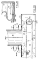
- the outer drum 68 is best illustrated in FIGS. 5 through 9, 15 and 15A.
- This drum as well as other parts of the converter 12 which are at high temperatures are desirably made of stainless steel of the type and class capable of sustaining such temperatures.
- the bulkheads 157 and 158 are plates which are connected, in the case of the bulkhead 157 to the inner end 58 of the injection tube 18.
- the space between these gussets may be filled with insulating material, such as rock wool which is also shown at 52.
- the bulkheads 157 and 158 and their associated components therefore provide part of the oven casing. As well as serving the dual function of sealing the chamber in which the rotary drum is located and pyrolysis reactions occur.
- the outer drum has longitudinal fins 94 which direct the combustion gases heated by the heater, and which pass through the heat source inlet 108, towards the outlet flue 24. These fins 94 are circumferentially spaced around the stationary outer drum 68. Between the longitudinal fins 94 (which also extend in the direction of the axis of rotation of the rotating converter drum 66) are spacer fins 96. These spacer fins 96 are longitudinally spaced from each other in the direction of the axis of rotation of the converter drum 66. The spacers for example may be at 91 cm (three foot) intervals around the outside periphery of the stationary outer drum. These spacers create turbulence in the forced draft of hot gases which circulates through the oven chamber. Such turbulence enhances heat transfer from these hot gases to the outer drum, and thence to the chamber inside the outer drum 68, where the rotating drum 66 carries the feedstocks undergoing pyrolysis.
- the outer drum 68 may have a diameter of approximately 48.6 cm (19.125 inches) in a small scale (pilot) converter and a diameter of 203 cm (80 inches) in a full scale converter.
- the converter drum 66 for a small scale (pilot) converter may be 43 cm (17 inches) in diameter, while in a full capacity converter the diameter of the converter drum 66 may be 183 cm (72 inches).
- the support of the converter 12 on the frame 48 is provided by the roller 28 which extends under a wedge shaped support platform 49 having an upper surface 29 which is parallel to the axis of rotation of the converter drum and the drive shaft 102 (see FIG. 4).
- the lower surface is generally parallel to the surface of the ground or support pad 50 (is horizontal).
- the inclination of the wedge therefore is approximately equal to the inclination of the axis of rotation of the converter drum which may be approximately 6°.
- the rear or discharge end of the converter drum and the inlet end of the converter drum are at different elevations; the inlet end being higher than the discharge end.
- the discharge end of the converter drum 66 is supported by the drive shaft 102 which is in turn supported in bearings in a pillow block resting on the rear support platform 49. This pillow block is shown at 180 (see FIG. 20).
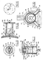
- the forward end of the converter drum 66 and the outer stationary drum are supported on roller assemblies 62.
- the roller assemblies 62 are shown in greater detail in FIGS. 10 to 14.
- a wear ring 110 is welded around the converter drum near the forward or inlet end thereof. Rollers 112 are rotatably mounted between thrust ball bearings 114 on a carrier 116. The wear ring 110 rests on the rollers 112.
- a plurality of roller assemblies are provided which are circumferentially spaced apart. Hardened bushings 118 surrounds ears extending laterally from each roller 112. These bushings 118 journal the rollers 112 in the carrier 116.
- the carrier is a rectangular block which rests on an inner pipe 122 of a pipe assembly including the inner pipe 122. This assembly contains an outer pipe 120 which is welded to a flange 126 and rests upon a blind flange 128.
- a shim disk 124 is located inside the outer pipe 120 under pipe 122, on the flange 128. By selecting the thickness of this shim the converter drum 66 may be adjusted.
- An adjustment to the inclination of the converter may be made by raising, (e.g., about 2° or lowering about 2°) the high end of the unit 12 at the support frame 48.
- the floating lower end of the discharge chute 30 inside the bellows 32 allows for this 2° plus or minus adjustment.
- Such adjustment will depend upon the nature of the feedstocks, since the angle of inclination of the converter drum determines the rate at which the feedstocks travel through the converter drum and their duration in the drum. Different feedstocks may require different lengths of time of pyrolysis in order to complete the pyrolysis reaction.
- An inlet and an outlet for pipes 132 and 144 which respectively carry water into and out of the chamber formed inside the inner pipe 122 are provided for cooling each roller assembly 62.
- a drain plug 130 or a drain valve may be used to drain the water from the roller assembly.
- the outer pipe 120 extends to the outer, stationary drum 68 and, with the aid of gussets 136, supports the roller assemblies 62.
- the oven casing has an inner shield or cover 138 and an outer shield or cover 140. These shields are separated by spacers 144.
- the spacers 144 are connected to support members 142 by being threaded therein. The spacers themselves are secured by spacer bolts 146.
- the support members 142 are attached to different ones of the longitudinal spacer fins 194 on the stationary outer drum 68. Six support members are shown which are spaced apart 60° from each other circumferentially around the stationary drum 68.
- the spaces between the shields 138 and 140 are desirably filled with insulating material, such as rock wool.
- a scraper assembly 64 is provided.
- This assembly includes a rod in a sleeve (not shown) which is welded to the upper (above the meridian through the axis of rotation of the converter drum) gussets 92 of the bulkhead 157.
- Scraper blades are yieldably connected, as by being mounted on springs (see FIG. 7) and engage the inside periphery of the converter drum 66 above the meridian through its axis of rotation.
- the converter drum 66 has torque rods 90 which are circumferentially spaced at equal angular increments and extend between the end of the rotating converter which is defined by bulkheads 150 and 152.
- These bulkheads are interconnected by gussets 156 which extend radially to the drive shaft 102 and may be welded thereto.
- the bulkheads 150 and 152 are disks which are also welded to the drive shaft 102.
- a ring or flange 154 extends longitudinally between the bulkheads.
- the torque rods are preferably welded to the ring 154 as well as to the gussets 156.
- the torque rods extend into the rear end of the converter drum 66 and are welded to the inner periphery thereof. These torque rods 90 define gaps or openings through which the solid products (residue) of pyrolysis reaction in the converter drum fall into the discharge chute 30.
- the length of these openings defined by the rods 90 may be 23 cm (nine inches) in a small-scale pilot converter 30 to 46 cm (twelve to eighteen inches) in a full-scale converter.
- the torque bars themselves may be six in number in a small-scale converter and 2.5 cm (one inch) in diameter. In a large-scale converter, twelve torque bars, 5 cm (two inches) in diameter, may be used.
- the opening in the outer drum 68 faces these openings in the converter drum and may 23 cm by 30 cm be (nine inches by twelve inches) (rectangular) for a small-scale converter and 46 cm by 41 cm (eighteen inches by sixteen inches) for a full-capacity converter.
- the discharge chute 30 may be rectangular where it meets the discharge opening.
- the duct work may vary to a circular cross-section from the rectangular cross-section in the lower part of the chute 30 where the bellows pipe 32 surrounds the chute 30.
- a preferably circular or octagonal crusher bar 70 having a length longer than the torque bars 90 but not more than twice the length of the torque bars is disposed loosely in the discharge end of the converter drum 66.
- the crusher bar 70 is picked up by the torque rods, elevated and then released, thereby crushing clumps in the residue and pulverizing them into particles which fall down through the openings between the torque bars 90.
- the weight of this residue overcomes the pressure presented by the water in the discharge chute so that the residue drops through the discharge chute and the water into the conveyor housing 82 (FIGS. 27-32) where a conveyor having scraper blades 80 pick up the residue and carries it up to a discharge snout 84.
- a source of a reagent which reacts with chlorine in such hydrocarbons may be injected in the inlet end of the converter drum.
- lime may be used which is injected via a control valve 98 through an injection pipe 100 into the inlet end of the converter drum 66 below the meridian thereof (the generally horizontally disposed plane through the axis of rotation of the drum 66).
- Calcium in the lime reacts with the chlorine of the chlorinated hydrocarbons to produce calcium chloride which is cleaned from the residue (mostly char) discharged via the water bath in the conveyor housing 82 and the chute tube 30.
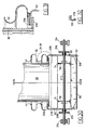
- the drive shaft assembly 22 is water cooled so that it can operate reliably in the high temperature environment of the converter 12.
- the drive shaft assembly includes the drive shaft 102 and a journal 106.
- a thrust washer 104 is disposed between the bulkhead plate 152 at the rear end of the converter drum and the bulkhead 158 at the rear end of the outer, stationary drum.
- the journal 106 defines a stuffing box containing high-temperature packing 164 and a chamber where water is contained as it is circulated between a water inlet 160 and a water outlet 162.
- the packing 164 is contained by a packing gland 166 which is also water cooled within a chamber thereof defined by a bellows 170.
- the bellows 170 may be welded at the end thereof to the flange of the gland 166 and to a seal carrier 174.
- the welds are shown at 172.
- a seal 176 preferably of the Garlock type, extends around the drive shaft 102 in the seal carrier 174.
- the water connection 168 is dead-headed. It may be connected to a T-connector through which water circulates. Accordingly, there may be a convective flow of water which cools the seal and the shaft 102.
- the water is pressurized at the same pressure as the inside of the converter and the discharge chute; or slightly above to ensure that no gases can escape through seal 164. A small water leak into the converter can be tolerated.
- the shaft 102 also has a cavity 178 (a hole) bored therein which extends into the area of the journal 106.
- a jack shaft 186 extends rearwardly from the drive shaft 102 and is connected through a swivel 188 which has a water inlet connection 190.
- a T-connection for water circulating past the swivel may be provided to accommodate convective flow of the water in the cavity 178.
- a small pipe may be inserted through the swivel into the far end of the water cavity 178 which forces cool water to the far end of the cavity, while discharging the warm water through the same swivel.
- the pillow block which supports the drive shaft and through which the rear end of the converter 12 is supported, is shown at 180 and FIG. 20, and was discussed above.
- the shaft drive sprocket 182 is also shown in FIG. 20 keyed to the shaft by a key 184. This drive sprocket 182 is connected via the chain 185 and sprocket 187 to the gear box 183 as shown in FIG. 3.
- the discharge chute 30 and the conveyor assembly 34 were mentioned above in connection with FIGS. 27-32.
- the upper end of the bellows pipe 32 is fixed to the outer periphery of the chute by gussets 200 and flanges 204 (FIG. 25 and 26).
- a bleed-off valve to allow air to bleed from the bellows above the water level therein is shown at 202.
- the bellows pipe is connected by being welded to a ring 206 which is spaced above the inverted end of the sides 208 of the conveyor housing 82. This inverted end is sandwiched between the ring 206 and a flange 210 around the bottom of the chute 30. As shown in FIG.
- the bellows pipe 32 enables movement of the discharge chute with respect to the conveyor housing 82 and accommodates such movement. Even in a small-scale converter, the movement may be two and one-half inches due to thermal expansion of the converter 12. Such movement is accommodated by the bellows pipe arrangement which enables relative motion of the discharge chute 30 with respect to the conveyor housing 82 while maintaining the liquid seal.
- An underwater support sprocket 78, FIG. 30 for the roller chain 74 of the conveyor is carried on a shaft 213 by being keyed thereto.
- This shaft is journaled in stuffing boxes 216 on the side walls 208 of the conveyor housing 82.
- the shaft is journaled and supported in pillow blocks 214.
- the scraper blades 80 are carried on the chain 74.
- the end tips 218 of the blades 80 are bent up (FIG. 32) and in a forward direction in which the conveyor is moving in order to collect and sweep the solid products (residues) along the floor of the conveyor housing 82 and push them out of the exit snout 84 (FIG. 25).
- the pyrolysis reactions occur while the feedstocks are being carried by the rotary motion of the converter drum 66 up the inner periphery of the drum.
- the feedstocks overcome the angle of repose, they tumble down and have a component of forward motion due to the inclination of the axis of the drum.
- the inclination used is selected in accordance with the feedstocks which are to be processed in order to give the required residence time in the converter for completion of pyrolysis.
- a steeper angle shortens the residence time, because the materials are carried up the side walls generally perpendicular to the axis of rotation and tumble back down in a direction which is essentially vertical.
- the gases consisting of methane, water vapor and other volatiles are released during pyrolysis of the materials and exit the outlet 87 to the delivery pipe 42.
- This delivery pipe first enters the condenser 44 (see FIGS. 33 to 35) which contains a bath of water to a level 222 above which is a layer of oil to a level 220.
- the oil may be provided by the condensed hydrocarbon gases which are delivered through the pipe 42.
- These gases flow under pressure, since the converter inner drum is pressurized (for example, to 1.358 x 10⁵ Pa (5 PSIG) as noted above).
- Baffles 224 direct the gases into the oil, since they are not long enough to extend below the water level 222. Longer baffles 224 direct the gases into the water.
- baffles cause the gases to circulate and be cleaned of impurities such as carbon particles, ash, calcium choride (the product of lime added to the process in the converter drum plus chlorine from chlorinated plastic such as vinyls, PCBs and the like). Also, sulfur and ammonia are cleaned from the gases.
- the temperature in the bath is maintained so as to condense aromatics, light and heavy oils without separation and water vapors if a single condenser 44 is used. If multiple condensers are used, upstream condensers which are of the fluid swept, rather than fluid bath type, are used to condense first heavy oils then light oils as temperatures decrease while the last condenser 44 condenses aromatics and water vapor.
- the condenser 44 also functions as a trap to prevent air from entering the converter(s).
- the oils which are condensed are removed from the oil layer, for example, by valved pipes or outlets which maintain the level 220.
- the water below the level 224 may be circulated through heat exchangers or chillers and maintained at the temperature for condensing aromatics and water vapor.
- treatment facilities may be provided to maintain the water at a desired pH level.
- non-condensable gases may be used for operating the burners to heat the converter 12. Alternatively, they may be compressed and stored for later use in the process (for example, on startup instead of propane) or for other purposes.
- FIGS. 36, 37 and 38 A fluid swept condenser is shown in FIGS. 36, 37 and 38.
- This condenser includes baffles 228 which like the baffles 224 of the condenser 44 may be connected to and supported by opposite side walls of the condenser housing. Alternate ones of these baffles extend below the fluid level 222 and cause the gas stream to sweep over the fluid.
- These condensers are identified by reference numeral 226 to differentiate them from the baffles in the condensers 44.
- a series of condensers 44 and 226 may be connected in tandem for processing condensing and cleaning the product gases from a plurality 230 to 234 of converters as shown in FIG. 39 or from a single converter.
- the last condenser in the series is of the fluid bath type 44, while the remaining condensers 238, 240 and 242 are of the fluid swept type 226.
- These fluid swept condensers force the gases to expand and contract to create turbulence and cool as they sweep above the fluid.
- the temperatures of the various condensers may be gradually decreased.
- the temperature of the first condenser 238 may be controlled to be at 177°C (350°F), the second 240 at 143°C (290°F), and third 242 at about 110°C 230°F and the last 44 at about 60°C (140°F). These temperatures are sufficient to keep water vapors in suspension in the gas stream until the last condenser 44 is reached, while allowing light and heavy oils to condense and also permitting the cleaning of the impurities in the gas stream. Since, the temperature of the last condenser 44 is about 60°C (140°F), most light aromatics and water vapors are condensed therein as discussed above.
- cool water may be circulated via a chiller or heat exchanger 245 or from the public water supply to the lowest temperature condenser 44.
- Warmer water is withdrawn from the lower temperature condensers and then circulated to the higher temperature condensers, thus by maintaining only one temperature, all of the temperatures of the condensers in the series may be maintained.
- the oil may be extracted by withdrawing it as it is separated from the gas stream in each of the condensers as shown by the outlets 247 from each of the condensers.
- the non-condensable gases are desirably compressed and stored in a tank 248 and then used in the heat source (burners) 26.
- the chimneys or flues 24 of the first converter 230 may be connected via ducts 252 to the heat source 26 of the next successive converter 232.
- the flue 24 of the converter 232 may be connected to the next converter 234.
- the chimney of the last converter 234 may be allowed to dissipate or may be connected to a burner to burn off any combustibles therein.
- the chimney 24 may be connected by another duct (not shown) to the burner 26 of the first converter 230.
- the temperature within the converter drum in the converter 12 or in the plurality of converters 230, 232 and 234 is desirably maintained at approximately 649°C (1200°F). This temperature may be insufficient to reduce certain chlorinated hydrocarbons to within levels considered environmentally safe.
- PCBs may be contained in the residue from the discharge chute 30.
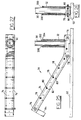
- a secondary converter 254 which is operated at higher temperature may be used. The residue is fed into the inlet end of a converter drum 258 of the secondary converter 254 by a chute 256 (see FIG. 40).
- the converter 254 is similar in design to the converter 10 as described above in connection with FIGS. 1-38. It has an outer stationary drum 260, a casing 52 defining an oven chamber, and a drive shaft assembly 262.
- the auxiliary converter is supported on additional members of the framework 48.
- the discharge from the secondary converter 254 is through a chute 30 and conveyor assembly 34 of the type described in connection with FIGS. 1-38, and like parts are identified by reference numerals used in describing them in connection with FIGS. 1-38.
- the burner of the secondary converter 254 desirably operates to heat the chamber containing the converter drum 258 to about 1316°C (2400°F) which is believed sufficient to destroy the PCBs upon pyrolyzation. This temperature is only approximate and such temperatures are used which are sufficient to provide a residue which is within environmentally safe levels.
Landscapes
- Engineering & Computer Science (AREA)
- Chemical & Material Sciences (AREA)
- Oil, Petroleum & Natural Gas (AREA)
- Organic Chemistry (AREA)
- Materials Engineering (AREA)
- General Engineering & Computer Science (AREA)
- Mechanical Engineering (AREA)
- Combustion & Propulsion (AREA)
- General Chemical & Material Sciences (AREA)
- Chemical Kinetics & Catalysis (AREA)
- Processing Of Solid Wastes (AREA)
- Processes Of Treating Macromolecular Substances (AREA)
- Crystals, And After-Treatments Of Crystals (AREA)
- Coke Industry (AREA)
- Production Of Liquid Hydrocarbon Mixture For Refining Petroleum (AREA)
Claims (19)
- Pyrolytisches Konversionssystem für Kohlenwasserstoff enthaltenden Materialien, das folgendes aufweist: eine offene Konvertertrommel mit gegenüberliegenden Enden, von denen ein erstes oberhalb eines zweiten von diesem erhöht ist, wobei die Trommel eine Rotations- bzw. Drehachse besitzt, um die die Konvertertrommel drehbar ist, eine äußere stationäre Trommel angeordnet um die Konvertertrommel und die eine erste Kammer definiert, innerhalb der die Konvertertrommmel angeordnet ist, ein Gehäuse angeordnet um die äußere Trommel, die eine Ofenkammer definiert, Mittel zum Erwärmen bzw. Erhitzen der Ofenkammer, um die Konvertertrommel auf einer Temperatur zu halten, die ausreicht, die Materialien zu pyrolysieren, Mittel in Verbindung mit der ersten Kammer in der Nähe des ersten Endes der Konvertertrommel zum Extrahieren bzw. Herausziehen von Produktgasen der Pyrolysation, Mittel angeordnet in im wesentlichen luftdichter Beziehung mit der ersten Kammer in der Nähe des zweiten Endes der Konvertertrommel für den Ablaß bzw. die Entladung von soliden bzw. festen Produkten der Pyrolysation und Mittel, die sich durch die erste Kammer erstrecken zum Injizieren bzw. Einspritzen bzw. Einführen der Materialien in das erste Ende der Konvertertrommel, während im wesentlichen Luft von der ersten Kammer ausgeschlossen wird.
- System nach Anspruch 1, wobei die Erwärmungsmittel folgendes aufweisen: einen Einlaß für erwärmte Gase in den Ofen in der Nähe des zweiten Endes der Konvertertrommel und einen Auslaß für die erwärmten Gase in der Nähe des ersten Endes der Konvertertrommel, und eine Wärmequelle verbunden mit dem Einlaß und einem Kamin bzw. Flammkanal verbunden mit dem Auslaß.
- System nach Anspruch 2, wobei die äußere Trommel folgendes aufweist: einen ringförmigen Außenumfang, und zwar exponiert bzw. ausgesetzt zu der Ofenkammer, eine Matrix von ringförmigen Flossen und längs angeordneten Flossen, die von dem Außenumfang in die Ofenkammer vorstehen zum Aufbau einer turbulenten Strömung der erwärmten Gase durch die Ofenkammer in Wärmeaustauschbeziehung mit den Flossen.
- System nach Anspruch 2, wobei die äußere Trommel und das Gehäuse Böden bzw. Unterseiten besitzen, und zwar angeordnet unterhalb der Achse, wobei die Ablaßmittel eine Rutsche bzw. eine Ablaßeinrichtung aufweisen, die sich in die erste Kammer durch die Böden der äußeren Trommel und das Gehäuse erstreckt, und zwar zu einer Stelle benachbart dem zweiten Ende der Konvertertrommel, wobei die Konvertertrommel offen zu dieser Stelle ist, und wobei der Wärmeinlaß in dem Boden des Gehäuses angeordnet ist, und zwar beabstandet weg von der Rutsche zu dem ersten Ende der Konvertertrommel.
- System nach Anspruch 4, wobei die Rutsche mit Flüssigkeit gefüllt ist, und zwar auf ein Niveau, das ausreicht, um mindestens im Gleichgewicht mit dem Druck in der ersten Kammer zu stehen, und wobei die Ablaßmittel eine Anordnung aufweisen, die die Flüssigkeit und eine Fördereinrichtung enthält, wobei sich die Fördereinrichtung zu dem Boden der Rutsche erstreckt und mit diesem in Verbindung steht, und zwar zum Tragen und Ablassen bzw. Entladen der festen Produkte oberhalb des Niveaus der Flüssigkeit in der Rutsche.
- System nach Anspruch 5, das weiter folgendes aufweist: Mittel, die das Gehäuse, die äußere Trommel und die Konvertertrommel tragen, und zwar für eine Längsbewegung in einer Richtung entlang der Achse ansprechend auf eine thermische Ausdehnung bzw. Expansion und Kontraktion, und Mittel, die die Rutsche an der Anordnung befestigen für eine Bewegung mit dem Gehäuse, der äußeren Trommel und der Konvertertrommel.
- System nach Anspruch 1, das weiter folgendes aufweist: Mittel zum Tragen der Konvertertrommel für eine Drehung, die folgendes aufweisen: eine Vielzahl von Rollen, die voneinander versetzt sind, auf denen die Konvertertrommel aufliegt, und zwar benachbart zu dem ersten Ende davon, Säulenmittel bzw. Mittel, die sich durch die erste Trommel erstrecken, und zwar in im wesentlicher luftdichter Beziehung damit zum Tragen der Rollen, einen Boden, der das zweite Ende der Konvertertrommel definiert, eine Antriebswelle, die mit dem Konvertertrommelboden verbunden ist und in abgedichteter Beziehung in der ersten Kammer gelagert ist, wobei die erste Kammer erste und zweite Enden an gegenüberliegenden bzw. entgegengesetzten Enden der äußeren Trommel besitzt, wobei die ersten bzw. zweiten Enden zu den ersten und zweiten Enden der Konvertertrommel hinweisen, wobei die Welle sich durch das zweite Ende der ersten Kammer erstreckt und ferner Mittel, die die Welle drehbar tragen.
- System nach Anspruch 7, das weiter folgendes aufweist: Streben bzw. Holme zwischen dem Ofenkammergehäuse und der äußeren Trommel zum Tragen der Ofenkammer auf der äußeren Trommel, wobei die äußere Trommel ebenfalls in tragender Beziehung mit den Säulenmittel verbunden sind, und wobei das Gehäuse eine innere und äußere Schale besitzt, die ein Wärmeschild vorsehen, wobei die Schalen voneinander beabstandet sind und eine Isolierung zwischen den Schalen angeordnet ist.
- System nach Anspruch 1, wobei die Konvertertrommel eine Stange besitzt, und zwar locker angeordnet darinnen entlang einer Achse davon benachbart zu dem zweiten Ende davon und ferner Mittel innerhalb der Konvertertrommel zum Anheben und Freigeben der Stange, was der Stange gestattet, zu fallen und die festen Produkte in Partikel zu pulverisieren, die in die Ablaßmittel eintreten.
- System nach Anspruch 9, wobei die Anhebungs- und Freigabe- bzw. Lösemittel folgendes aufweisen: einen Boden, der das zweite Ende der Konvertertrommel definiert, eine Vielzahl von Stäben, und zwar umfangsmäßig beabstandet voneinander und sich längs in einer Richtung entlang der Achse der Konvertertrommel von dem Boden zu dem ersten Ende der Konvertertrommel erstrecken, wobei eine Vielzahl der Stäbe eine Öffnung dazwischen definieren, für den Ablaß der festen Produkte, wobei die Stäbe mit der Zertrümmerungsstange in Eingriff kommen, diese anheben und freigeben, wenn sich die Konvertertrommel dreht.
- System nach Anspruch 1, wobei die Konvertertrommel einen Innenumfang besitzt und ferner Mittel aufweist, die sich entlang der Achse der Konvertertrommel erstrecken und in Eingriff kommen mit dem Innenumfang, um Material von dem Innenumfang abzukratzen, wenn sich die Konvertertrommel dreht.
- System nach Anspruch 1, wobei die Einspritz- bzw. Injiziermittel folgendes aufweisen: ein Rohr bzw. Schlauch, das durch das erste Ende der Konvertertrommel vorsteht, so daß ein Ende des Rohres in die Konvertertrommel vorsteht, wobei das Rohr einen Querschnitt besitzt, Mittel zum Liefern der Materialien zu der Konvertertrommel in Ballen oder Säcken, die sukzessive in einer Ende-an-Ende-Beziehung in dem Rohr angeordnet sind, wobei die Ballen einen Querschnitt besitzen, und zwar ungefähr mit denselben Abmessungen, wie der Querschnitt des Rohres, um eine im wesentlichen luftdichte Dichtung in dem Rohr zu bilden, und Öffnungen in dem Rohr zum Ablassen von Strömungsmittel, das in dem Rohr und zwischen den Ballen oder Säcken, die in das Rohr eintreten, und Ballen vor den eintretenden Ballen oder Säcken gefangen ist.
- System nach Anspruch 12, wobei die Einführ- bzw. Injiziermittel weiter folgendes aufweisen: einen Trichter bzw. Behälter zum Enthalten der Ballen mit oberen und unteren Enden, eine schwenkbare Abdeckung, die sich über das untere Ende erstreckt und einen Teil des Rohres unterhalb des Trichters definiert, und Mittel zum Schwenken der Abdeckung in eine offene Position, um den Ballen zu gestatten, von dem Trichter in das Rohr einzutreten, und zwar einem für jeden Zeitpunkt, und wobei die Mittel zum Schwenken folgendes aufweisen: einen Ramme bzw. Rammittel, die einen Plunger bzw. Kolben mit Querschnittsdimensionen besitzen, die ungefähr dieselben wie der Querschnitt des Rohres sind, wobei der Plunger hin- und herbewegbar ist über den Teil des Rohres, um die eintretenden Ballen der Folge von Ballen entlang des Rohres in die Konvertertrommel zu rammen bzw. zu stoßen.
- System nach Anspruch 1, wobei die Mittel zum Extrahieren bzw. Herausziehen von Produktgasen folgendes aufweisen: eine Vielzahl von Strömungsmittel enthaltenden Kondensatoren bzw. Verflüssigungsvorrichtungen und Mittel zum Verbinden der Kondensatoren, und zwar in Tandem bzw. hintereinander angeordnet für die Strömung der Produktgase sukzessive dahindurch.
- System nach Anspruch 14, das weiter folgendes aufweist: Mittel zum Halten der Bäder in den Kondensatoren bei aufeinanderfolgend niedrigeren Temperaturen, wobei die höchste der Temperaturen in einem der Kondensatoren ist, durch den die Gase von der Konvertertrommel zuerst passieren, und wobei die Temperatur in dem letzten von den in Tandem angeordneten verbundenen Kondensatoren unterhalb der Kondensationstemperatur von Wasserdampf ist.
- System nach Anspruch 1, wobei eine Vielzahl von pyrolytischen Konvertern vorgesehen ist, wobei jeder die Elemente gemäß Anspruch 1 besitzt und ferner folgendes aufweist: gemeinsame Mittel verbunden mit den Produktgasherausziehmittel der Konverter zum Reinigen der Produktsgase und zum Liefern von mindestens einigen der Produktgase an die Erwärmungsmittel der Konverter für eine Verbrennung darinen, wobei die Konverter einen Kamin bzw. Abzug besitzen, der sich von den Ofenkammern davon erstreckt, und zwar in der Nähe der ersten Enden der Konvertertrommel davon und Mittel zum Verbinden des Kamins von mindestens einem der Vielzahl von Konvertern mit den Erwärmungmsitteln eines anderen der Vielzahl von Konvertern zum Vorerwärmen der Erwärmungsmittel.
- System nach Anspruch 1, das ferner Mittel aufweist zum Einführen- bzw. Injizieren von Calcium enthaltendem Material in das erste Ende der Konvertertrommel.
- System nach Anspruch 1, das ferner einen zweiten pyrolytischen Konverter aufweist, und zwar mit einem Einlaß für feste Materialien und einem Ablaßauslaß für feste pyrolysierte Materialien, wobei der Einlaß mit den Ablaßmitteln verbunden ist.
- System nach Anspruch 18, wobei der zweite pyrolytische Konverter folgendes aufweist: eine zweite Konvertertrommel, und zwar mit einer Achse geneigt nach unten von dem Einlaß zu dem Ablaßauslaß davon, eine zweite stationäre äußere Trommel, um die Konvertertrommel, die eine zweite Kammer definiert durch die sich der Einlaß erstreckt, ein Gehäuse um die zweite Trommel, das eine zweite Ofenkammer definiert, wobei der Ablaß des zweiten Konverters eine Rutsche bzw. eine Ablaßeinrichtung aufweist, und zwar in Verbindung mit der zweiten Konvertertrommel an dem unteren Ende davon und Mittel assoziiert mit der Rutsche zum Halten der ersten Kammer und der zweiten Kammer in einer im wesentlichen luftichten Beziehung.
Applications Claiming Priority (2)
| Application Number | Priority Date | Filing Date | Title |
|---|---|---|---|
| US07/494,256 US5082534A (en) | 1990-03-14 | 1990-03-14 | Pyrolytic conversion system |
| US494256 | 1990-03-14 |
Publications (2)
| Publication Number | Publication Date |
|---|---|
| EP0446930A1 EP0446930A1 (de) | 1991-09-18 |
| EP0446930B1 true EP0446930B1 (de) | 1995-08-30 |
Family
ID=23963731
Family Applications (1)
| Application Number | Title | Priority Date | Filing Date |
|---|---|---|---|
| EP91103962A Expired - Lifetime EP0446930B1 (de) | 1990-03-14 | 1991-03-14 | Pyrolitisches Konvertierungssystem |
Country Status (6)
| Country | Link |
|---|---|
| US (1) | US5082534A (de) |
| EP (1) | EP0446930B1 (de) |
| JP (1) | JPH06212163A (de) |
| AT (1) | ATE127143T1 (de) |
| CA (1) | CA2038146A1 (de) |
| DE (1) | DE69112458T2 (de) |
Cited By (2)
| Publication number | Priority date | Publication date | Assignee | Title |
|---|---|---|---|---|
| DE102006013617A1 (de) * | 2006-03-22 | 2007-09-27 | Universität Kassel | Biomassevergaser |
| US8038848B2 (en) | 2007-03-23 | 2011-10-18 | Buhr Harvey | Recycling of tires, rubber and other organic material through vapor distillation |
Families Citing this family (46)
| Publication number | Priority date | Publication date | Assignee | Title |
|---|---|---|---|---|
| US5707592A (en) * | 1991-07-18 | 1998-01-13 | Someus; Edward | Method and apparatus for treatment of waste materials including nuclear contaminated materials |
| US5230777A (en) * | 1991-12-13 | 1993-07-27 | James Jarrell | Apparatus for producing fuel and carbon black from rubber tires |
| US5366595A (en) * | 1993-05-11 | 1994-11-22 | Padgett Michael A | Mobile apparatus for pyrolyzing carbonaceous material and related method |
| DE4329871A1 (de) * | 1993-09-03 | 1995-03-09 | Siemens Ag | Innenberohrte, drehbare Heizkammer für Abfall |
| FR2720479B1 (fr) * | 1994-05-30 | 1996-07-12 | Inst Francais Du Petrole | Procédé et installation de pyrolyse de déchets ayant une unité de préchauffage. |
| FR2720487B1 (fr) * | 1994-05-30 | 1996-07-12 | Inst Francais Du Petrole | Four tournant de pyrolyse de déchets avec chauffage interne. |
| FR2725387B1 (fr) * | 1994-10-06 | 1996-12-27 | Inst Francais Du Petrole | Procede et dispositif de neutralisation de gaz acides et d'elimination de dechets |
| DE19528018B4 (de) * | 1995-07-31 | 2005-12-15 | Eisenmann Maschinenbau Gmbh & Co. Kg | Anlage für die thermische Behandlung von organische Bestandteile aufweisenden Materialien zur thermischen Entsorgung von Abfallstoffen, Haus-, Industrie- und/oder Sondermüll, chemischen Rückständen und/oder dergleichen |
| AUPN585795A0 (en) * | 1995-10-06 | 1995-11-02 | Tox Free Systems Inc. | Volatile materials treatment system |
| AU712838B2 (en) * | 1995-10-06 | 1999-11-18 | Tox Free Systems Limited | Volatile materials treatment system |
| AU705861B2 (en) * | 1995-10-06 | 1999-06-03 | Tox Free Systems Limited | Volatile materials treatment system |
| ES2157715B1 (es) * | 1998-03-12 | 2002-03-01 | Simo Antonio Belenguer | Horno tubular para la pirolisis en atmosfera controlada de productos que descomponen a menos de 500 c y recuperacion de los solidos inertes que le acompañan. |
| FR2779441B1 (fr) * | 1998-06-08 | 2000-08-11 | Thide Environnement | Four de thermolyse a double entree de dechets |
| US7344622B2 (en) * | 2003-04-08 | 2008-03-18 | Grispin Charles W | Pyrolytic process and apparatus for producing enhanced amounts of aromatic compounds |
| JP2007508922A (ja) * | 2003-10-02 | 2007-04-12 | ミシシッピ・ステイト・ユニバーシティ | 廃水処理プラント汚泥からのバイオディーゼル燃料及び他の有用な化学物質の生成 |
| CA2583617C (en) * | 2004-10-13 | 2013-09-03 | Charlie Holding Intellectual Property, Inc. | Pyrolytic process and apparatus for producing enhanced amounts of aromatic compounds |
| GB0514282D0 (en) * | 2005-07-12 | 2005-08-17 | Item Wales Ltd | Pyrolysis system |
| KR100777812B1 (ko) * | 2005-10-12 | 2007-11-28 | 김영호 | 폐합성수지를 이용한 터널식 열분해유 재생장치 |
| US8382959B2 (en) * | 2006-04-25 | 2013-02-26 | M-I Drilling Fluids International B.V. | Transportable hydrocarbon-recovery unit |
| US8444828B2 (en) * | 2006-12-26 | 2013-05-21 | Nucor Corporation | Pyrolyzer furnace apparatus and method for operation thereof |
| US9045693B2 (en) | 2006-12-26 | 2015-06-02 | Nucor Corporation | Pyrolyzer furnace apparatus and method for operation thereof |
| US9120977B1 (en) | 2007-03-23 | 2015-09-01 | The Harvey Buhr And Betty Buhr Trust | Recycling of tires, rubber and other organic material through vapor distillation |
| US8317980B2 (en) * | 2008-09-17 | 2012-11-27 | Nantong Tianyi Environment And Energy Technology Limited Corporation | Reactor for converting waste materials into fuel, a feeding system for feeding waste materials into the reactor, and methods for converting waste materials into fuel |
| KR100937214B1 (ko) * | 2008-10-08 | 2010-01-20 | 주식회사 에이쓰 | 폐타이어 재활용 시스템 |
| WO2010106538A1 (en) * | 2009-03-17 | 2010-09-23 | T.D.E. Recovery Technologies Ltd. | A pyrolytic reactor |
| KR100946714B1 (ko) | 2009-05-26 | 2010-03-12 | 한국기계연구원 | 바이오 원유 제조 장치, 바이오 원유 제조 시스템 및 바이오 원유 제조 방법 |
| EP2454341B1 (de) | 2009-07-17 | 2018-03-21 | Green Energy and Technology SDN BHD | Verfahren und vorrichtung zur zersetzung von kautschukprodukten durch pyrolyse |
| CN101634452A (zh) * | 2009-08-13 | 2010-01-27 | 牛斌 | 连续除氯工艺及设备 |
| WO2011031249A1 (en) * | 2009-09-08 | 2011-03-17 | John Scahill | Fast pyrolysis system |
| CN101985558B (zh) * | 2010-08-19 | 2012-01-04 | 西峡龙成特种材料有限公司 | 煤物质的分解设备 |
| CN101985564B (zh) * | 2010-08-19 | 2011-09-14 | 西峡龙成特种材料有限公司 | 煤物质的立式分解设备 |
| CN103930746A (zh) * | 2011-09-12 | 2014-07-16 | 太浩科技有限公司 | 用于延时和延长的空气冷却冷凝系统的方法和装置 |
| CN103988021B (zh) | 2011-10-21 | 2016-06-29 | 塞尔马-弗莱特公司 | 气化系统及其方法,以及废物处理系统及其使用方法 |
| CN102585863B (zh) * | 2012-02-21 | 2014-01-15 | 西峡龙成特种材料有限公司 | 筒套型煤物质分解装置 |
| AU343833S (en) * | 2012-06-26 | 2012-08-10 | Adelaide Control Eng Pty Ltd | A containerised rotary kiln dryer module |
| US9850430B2 (en) * | 2013-03-12 | 2017-12-26 | Amec Foster Wheeler Usa Corporation | Method and system for utilizing selectively de-coupleable connections for modular installation of a coke drum |
| KR101555282B1 (ko) * | 2014-01-10 | 2015-09-23 | 에코플랜트 주식회사 | 재생오일 생산장치용 폐원료 가열장치 |
| RU2016142396A (ru) * | 2014-03-31 | 2018-05-07 | Данмаркс Текниске Университет | Ротор для центробежного пиролизера |
| CN104694166B (zh) * | 2015-02-15 | 2017-10-31 | 华东理工大学 | 一种分级热解气化系统及其应用、制革废弃物的处理方法 |
| JP6130573B1 (ja) * | 2016-10-27 | 2017-05-17 | 武夫 河原井 | バイオマス燃料製造装置 |
| CN108913174A (zh) * | 2018-09-21 | 2018-11-30 | 商丘瑞新通用设备制造股份有限公司 | 一种防治结焦粘壁的裂解装置及裂解设备 |
| CN109529446B (zh) * | 2018-12-30 | 2021-02-02 | 江苏环保产业技术研究院股份公司 | 一种垃圾处理用废液滤清回收的旋压式过滤设备 |
| CN109868377B (zh) * | 2019-02-26 | 2021-06-11 | 李为祥 | 一种稀土沉淀灼烧设备 |
| CH716009B1 (fr) * | 2019-03-29 | 2022-10-14 | Greenlina Sa | Procédé de transformation par pyrolyse de déchets mélangés en matières plastiques et en caoutchoucs et dispositif pour la mise en oeuvre du procédé. |
| CN111842400A (zh) * | 2019-04-25 | 2020-10-30 | 湖南科谷环保科技有限公司 | 一种聚苯乙烯废弃物热解利用装置 |
| CN113154872B (zh) * | 2021-04-22 | 2022-07-19 | 重庆科技学院 | 一种低温等离子体组合式回转窑 |
Family Cites Families (40)
| Publication number | Priority date | Publication date | Assignee | Title |
|---|---|---|---|---|
| US1171583A (en) * | 1915-08-11 | 1916-02-15 | Winfield S Barnes | Ore-roasting apparatus. |
| US1236885A (en) * | 1916-05-27 | 1917-08-14 | Seaman Waste Wood Chemical Company Inc | Apparatus for destructive distillation. |
| GB146287A (en) * | 1916-11-13 | 1921-08-11 | Fischer Franz | Improvements in and relating to the distillation of coal |
| US1647273A (en) * | 1926-05-26 | 1927-11-01 | American Hydrocarbon Co Inc | Apparatus for extracting volatile matter |
| US1881826A (en) * | 1927-12-22 | 1932-10-11 | Coal Carbonization Company | Apparatus for carbonization of coal |
| DE638576C (de) * | 1930-04-23 | 1936-11-25 | Ile Cie Des Mines De Bruay Soc | Von aussen beheizter geneigter Drehrohrofen |
| US2697068A (en) * | 1952-02-11 | 1954-12-14 | Franklin E Poindexter | Rotatable carbonizing machine |
| US3098458A (en) * | 1961-11-01 | 1963-07-23 | Pan American Resources Inc | Rotary refuse converter |
| BE757441A (fr) * | 1969-10-14 | 1971-04-13 | Armstrong Richard M | Agencement pour monter des lames de raclage |
| US3787292A (en) * | 1971-08-13 | 1974-01-22 | E Keappler | Apparatus for pyrolysis of wastes |
| US3801469A (en) * | 1971-08-31 | 1974-04-02 | Scient Res Instr Corp | Method for effecting chemical reactions between cascading solids and counterflowing gases or fluids |
| GB1464517A (en) * | 1974-11-25 | 1977-02-16 | Electrolux Ab | Method of processing waste in a ship and apparatus and arrangement for carrying out the method |
| US4153514A (en) * | 1975-02-27 | 1979-05-08 | Occidental Petroleum Corporation | Pyrolysis process for solid wastes |
| US4038152A (en) * | 1975-04-11 | 1977-07-26 | Wallace-Atkins Oil Corporation | Process and apparatus for the destructive distillation of waste material |
| US3980439A (en) * | 1975-05-14 | 1976-09-14 | E. I. Du Pont De Nemours And Company | Fluidizing apparatus with foraminous member |
| DE2651302C3 (de) * | 1976-05-12 | 1981-07-09 | PLS Gesellschaft für Pyrolyse-Müllverwertungsverfahren mbH, 8000 München | Vorrichtung zur Destillationsgaserzeugung aus Abfall |
| US4064018A (en) * | 1976-06-25 | 1977-12-20 | Occidental Petroleum Corporation | Internally circulating fast fluidized bed flash pyrolysis reactor |
| US4145274A (en) * | 1976-06-25 | 1979-03-20 | Occidental Petroleum Corporation | Pyrolysis with staged recovery |
| US4102773A (en) * | 1976-06-25 | 1978-07-25 | Occidental Petroleum Corporation | Pyrolysis with cyclone burner |
| US4126519A (en) * | 1977-09-12 | 1978-11-21 | Edward Koppelman | Apparatus and method for thermal treatment of organic carbonaceous material |
| US4284616A (en) * | 1978-02-15 | 1981-08-18 | Intenco, Inc. | Process for recovering carbon black and hydrocarbons from used tires |
| DE2810838C3 (de) * | 1978-03-13 | 1982-07-22 | Herit AG, Vaduz | Drehtrommel zur Bildung thermischer Behandlungsräume für pyrolytische Zersetzungsfest- und -flüssigstoffe von Altbereifungen |
| US4183726A (en) * | 1978-04-13 | 1980-01-15 | Seebald John W | Pyro-processing rotary kiln mixing rod |
| US4374704A (en) * | 1978-08-24 | 1983-02-22 | Young William P | Apparatus for pyrolysis of hydrocarbon bearing materials |
| US4243489A (en) * | 1978-11-13 | 1981-01-06 | Occidental Petroleum Corp. | Pyrolysis reactor and fluidized bed combustion chamber |
| US4401513A (en) * | 1980-09-26 | 1983-08-30 | Brewer John C | Apparatus for pyrolyzing shredded tires |
| US4361333A (en) * | 1981-03-13 | 1982-11-30 | Tosco Corporation | Retort seal mechanism with integral bearings |
| US4463203A (en) * | 1981-11-13 | 1984-07-31 | Gi Kim D | Process for the preparation of fuel oil, fuel gas and pyrolysis coke by pyrolysis |
| US4367075A (en) * | 1981-11-16 | 1983-01-04 | Allis-Chalmers Corporation | Pressurized rotary kiln with thrust containment |
| US4404086A (en) * | 1981-12-21 | 1983-09-13 | Standard Oil Company (Indiana) | Radial flow retorting process with trays and downcomers |
| US4412889A (en) * | 1982-03-22 | 1983-11-01 | Kleenair Products Co., Inc. | Pyrolysis reaction apparatus |
| US4507174A (en) * | 1983-05-10 | 1985-03-26 | Kutrieb Wolfgang A | Tire pyrolizing |
| US4588477A (en) * | 1984-05-11 | 1986-05-13 | Habib Ikram W | Traveling fluidized bed distillation of scrap tires and rubber vulcanizate |
| JPS60257855A (ja) * | 1984-06-06 | 1985-12-19 | 川崎重工業株式会社 | ロツドミルの排出口部ライナ |
| US4647443A (en) * | 1984-10-12 | 1987-03-03 | Fred Apffel | Recovery process |
| US4648328A (en) * | 1985-09-30 | 1987-03-10 | Keough William R | Apparatus and process for the pyrolysis of tires |
| NZ222007A (en) * | 1986-10-02 | 1989-01-27 | Neutralysis Ind Pty Ltd | Treating waste material by pelletising and vitrifying |
| JPS6481294A (en) * | 1987-09-22 | 1989-03-27 | Juki Kk | Method and apparatus for forming thick-film circuit |
| US4872954A (en) * | 1987-11-24 | 1989-10-10 | Hogan Jim S | Apparatus for the treatment of waste |
| ES2006264A6 (es) * | 1988-01-11 | 1989-04-16 | Iriart Henrri Joseph F | Sistema para la transformacion de residuos. |
-
1990
- 1990-03-14 US US07/494,256 patent/US5082534A/en not_active Expired - Fee Related
-
1991
- 1991-03-13 JP JP3072056A patent/JPH06212163A/ja not_active Withdrawn
- 1991-03-13 CA CA002038146A patent/CA2038146A1/en not_active Abandoned
- 1991-03-14 DE DE69112458T patent/DE69112458T2/de not_active Expired - Fee Related
- 1991-03-14 EP EP91103962A patent/EP0446930B1/de not_active Expired - Lifetime
- 1991-03-14 AT AT91103962T patent/ATE127143T1/de not_active IP Right Cessation
Cited By (3)
| Publication number | Priority date | Publication date | Assignee | Title |
|---|---|---|---|---|
| DE102006013617A1 (de) * | 2006-03-22 | 2007-09-27 | Universität Kassel | Biomassevergaser |
| DE102006013617B4 (de) * | 2006-03-22 | 2008-07-03 | Universität Kassel | Biomassevergaser |
| US8038848B2 (en) | 2007-03-23 | 2011-10-18 | Buhr Harvey | Recycling of tires, rubber and other organic material through vapor distillation |
Also Published As
| Publication number | Publication date |
|---|---|
| DE69112458D1 (de) | 1995-10-05 |
| CA2038146A1 (en) | 1991-09-15 |
| EP0446930A1 (de) | 1991-09-18 |
| DE69112458T2 (de) | 1996-04-18 |
| JPH06212163A (ja) | 1994-08-02 |
| US5082534A (en) | 1992-01-21 |
| ATE127143T1 (de) | 1995-09-15 |
Similar Documents
| Publication | Publication Date | Title |
|---|---|---|
| EP0446930B1 (de) | Pyrolitisches Konvertierungssystem | |
| US5225044A (en) | Pyrolytic conversion system | |
| US5258101A (en) | Pyrolytic conversion system | |
| US5305533A (en) | Combined direct and indirect rotary dryer with reclaimer | |
| US6178899B1 (en) | Waste treatment method and waste treatment apparatus | |
| US5167772A (en) | Apparatus for pyrolysis of tires and waste | |
| US4038152A (en) | Process and apparatus for the destructive distillation of waste material | |
| US5927970A (en) | Apparatus for recovering hydrocarbons from solids | |
| US8168043B2 (en) | Retort apparatus and method for continuously processing liquid and solid mixtures and for recovering products therefrom | |
| US5453164A (en) | Pyrolytic conversion system | |
| US20100150658A1 (en) | System and method for treating oil-bearing media | |
| US4726301A (en) | System for extracting contaminants and hydrocarbons from cuttings waste in oil well drilling | |
| CN109477010A (zh) | 用于将废弃塑料转化成燃料的系统和工艺 | |
| US5205225A (en) | Apparatus for allowing thermal dimensional changes of metal parts in a retort mechanism | |
| JP2006089742A (ja) | 廃合成高分子化合物の連続式熱分解システム | |
| US5257586A (en) | Method and apparatus for feeding to a rotary device | |
| CN102245737A (zh) | 用于任何种类的有机材料的热解的装置和方法 | |
| AU2012359291B2 (en) | Continuous pyrolysis apparatus | |
| US5224432A (en) | Method for retorting organic matter | |
| US10604704B2 (en) | Shear retort for ablative pyrolysis | |
| RU2768809C1 (ru) | Мобильный модуль реактора пиролиза для комплексов термической переработки отходов | |
| US4325787A (en) | Apparatus for retorting comminuted oil shale | |
| GB2144836A (en) | Improvements in or relating to a pyrolysis reaction and apparatus | |
| US5220873A (en) | Apparatus for retorting organic matter | |
| US3471369A (en) | Production of char |
Legal Events
| Date | Code | Title | Description |
|---|---|---|---|
| PUAI | Public reference made under article 153(3) epc to a published international application that has entered the european phase |
Free format text: ORIGINAL CODE: 0009012 |
|
| AK | Designated contracting states |
Kind code of ref document: A1 Designated state(s): AT BE CH DE DK ES FR GB GR IT LI LU NL SE |
|
| 17P | Request for examination filed |
Effective date: 19920317 |
|
| 17Q | First examination report despatched |
Effective date: 19921022 |
|
| GRAA | (expected) grant |
Free format text: ORIGINAL CODE: 0009210 |
|
| AK | Designated contracting states |
Kind code of ref document: B1 Designated state(s): AT BE CH DE DK ES FR GB GR IT LI LU NL SE |
|
| PG25 | Lapsed in a contracting state [announced via postgrant information from national office to epo] |
Ref country code: IT Free format text: LAPSE BECAUSE OF FAILURE TO SUBMIT A TRANSLATION OF THE DESCRIPTION OR TO PAY THE FEE WITHIN THE PRESCRIBED TIME-LIMIT;WARNING: LAPSES OF ITALIAN PATENTS WITH EFFECTIVE DATE BEFORE 2007 MAY HAVE OCCURRED AT ANY TIME BEFORE 2007. THE CORRECT EFFECTIVE DATE MAY BE DIFFERENT FROM THE ONE RECORDED. Effective date: 19950830 Ref country code: AT Effective date: 19950830 Ref country code: BE Effective date: 19950830 Ref country code: FR Free format text: THE PATENT HAS BEEN ANNULLED BY A DECISION OF A NATIONAL AUTHORITY Effective date: 19950830 Ref country code: ES Free format text: THE PATENT HAS BEEN ANNULLED BY A DECISION OF A NATIONAL AUTHORITY Effective date: 19950830 Ref country code: DK Effective date: 19950830 Ref country code: GR Free format text: LAPSE BECAUSE OF FAILURE TO SUBMIT A TRANSLATION OF THE DESCRIPTION OR TO PAY THE FEE WITHIN THE PRESCRIBED TIME-LIMIT Effective date: 19950830 Ref country code: NL Free format text: LAPSE BECAUSE OF FAILURE TO SUBMIT A TRANSLATION OF THE DESCRIPTION OR TO PAY THE FEE WITHIN THE PRESCRIBED TIME-LIMIT Effective date: 19950830 |
|
| REF | Corresponds to: |
Ref document number: 127143 Country of ref document: AT Date of ref document: 19950915 Kind code of ref document: T |
|
| REF | Corresponds to: |
Ref document number: 69112458 Country of ref document: DE Date of ref document: 19951005 |
|
| PG25 | Lapsed in a contracting state [announced via postgrant information from national office to epo] |
Ref country code: SE Effective date: 19951130 |
|
| EN | Fr: translation not filed | ||
| NLV1 | Nl: lapsed or annulled due to failure to fulfill the requirements of art. 29p and 29m of the patents act | ||
| PG25 | Lapsed in a contracting state [announced via postgrant information from national office to epo] |
Ref country code: GB Effective date: 19960314 |
|
| PG25 | Lapsed in a contracting state [announced via postgrant information from national office to epo] |
Ref country code: LU Free format text: LAPSE BECAUSE OF NON-PAYMENT OF DUE FEES Effective date: 19960331 Ref country code: LI Effective date: 19960331 Ref country code: CH Effective date: 19960331 |
|
| PLBE | No opposition filed within time limit |
Free format text: ORIGINAL CODE: 0009261 |
|
| STAA | Information on the status of an ep patent application or granted ep patent |
Free format text: STATUS: NO OPPOSITION FILED WITHIN TIME LIMIT |
|
| 26N | No opposition filed | ||
| GBPC | Gb: european patent ceased through non-payment of renewal fee |
Effective date: 19960314 |
|
| REG | Reference to a national code |
Ref country code: CH Ref legal event code: PL |
|
| PG25 | Lapsed in a contracting state [announced via postgrant information from national office to epo] |
Ref country code: DE Effective date: 19961203 |