EP0446596A2 - PCVD process for the production of approximately dome-shaped substrates provided on the inside and/or outside with dielectric and/or metallic coating systems - Google Patents
PCVD process for the production of approximately dome-shaped substrates provided on the inside and/or outside with dielectric and/or metallic coating systems Download PDFInfo
- Publication number
- EP0446596A2 EP0446596A2 EP91101392A EP91101392A EP0446596A2 EP 0446596 A2 EP0446596 A2 EP 0446596A2 EP 91101392 A EP91101392 A EP 91101392A EP 91101392 A EP91101392 A EP 91101392A EP 0446596 A2 EP0446596 A2 EP 0446596A2
- Authority
- EP
- European Patent Office
- Prior art keywords
- gas
- displacement body
- coating
- layer
- coated
- Prior art date
- Legal status (The legal status is an assumption and is not a legal conclusion. Google has not performed a legal analysis and makes no representation as to the accuracy of the status listed.)
- Granted
Links
Images

Classifications
-
- C—CHEMISTRY; METALLURGY
- C23—COATING METALLIC MATERIAL; COATING MATERIAL WITH METALLIC MATERIAL; CHEMICAL SURFACE TREATMENT; DIFFUSION TREATMENT OF METALLIC MATERIAL; COATING BY VACUUM EVAPORATION, BY SPUTTERING, BY ION IMPLANTATION OR BY CHEMICAL VAPOUR DEPOSITION, IN GENERAL; INHIBITING CORROSION OF METALLIC MATERIAL OR INCRUSTATION IN GENERAL
- C23C—COATING METALLIC MATERIAL; COATING MATERIAL WITH METALLIC MATERIAL; SURFACE TREATMENT OF METALLIC MATERIAL BY DIFFUSION INTO THE SURFACE, BY CHEMICAL CONVERSION OR SUBSTITUTION; COATING BY VACUUM EVAPORATION, BY SPUTTERING, BY ION IMPLANTATION OR BY CHEMICAL VAPOUR DEPOSITION, IN GENERAL
- C23C16/00—Chemical coating by decomposition of gaseous compounds, without leaving reaction products of surface material in the coating, i.e. chemical vapour deposition [CVD] processes
- C23C16/44—Chemical coating by decomposition of gaseous compounds, without leaving reaction products of surface material in the coating, i.e. chemical vapour deposition [CVD] processes characterised by the method of coating
- C23C16/455—Chemical coating by decomposition of gaseous compounds, without leaving reaction products of surface material in the coating, i.e. chemical vapour deposition [CVD] processes characterised by the method of coating characterised by the method used for introducing gases into reaction chamber or for modifying gas flows in reaction chamber
- C23C16/45517—Confinement of gases to vicinity of substrate
-
- C—CHEMISTRY; METALLURGY
- C03—GLASS; MINERAL OR SLAG WOOL
- C03C—CHEMICAL COMPOSITION OF GLASSES, GLAZES OR VITREOUS ENAMELS; SURFACE TREATMENT OF GLASS; SURFACE TREATMENT OF FIBRES OR FILAMENTS MADE FROM GLASS, MINERALS OR SLAGS; JOINING GLASS TO GLASS OR OTHER MATERIALS
- C03C17/00—Surface treatment of glass, not in the form of fibres or filaments, by coating
- C03C17/001—General methods for coating; Devices therefor
-
- C—CHEMISTRY; METALLURGY
- C23—COATING METALLIC MATERIAL; COATING MATERIAL WITH METALLIC MATERIAL; CHEMICAL SURFACE TREATMENT; DIFFUSION TREATMENT OF METALLIC MATERIAL; COATING BY VACUUM EVAPORATION, BY SPUTTERING, BY ION IMPLANTATION OR BY CHEMICAL VAPOUR DEPOSITION, IN GENERAL; INHIBITING CORROSION OF METALLIC MATERIAL OR INCRUSTATION IN GENERAL
- C23C—COATING METALLIC MATERIAL; COATING MATERIAL WITH METALLIC MATERIAL; SURFACE TREATMENT OF METALLIC MATERIAL BY DIFFUSION INTO THE SURFACE, BY CHEMICAL CONVERSION OR SUBSTITUTION; COATING BY VACUUM EVAPORATION, BY SPUTTERING, BY ION IMPLANTATION OR BY CHEMICAL VAPOUR DEPOSITION, IN GENERAL
- C23C16/00—Chemical coating by decomposition of gaseous compounds, without leaving reaction products of surface material in the coating, i.e. chemical vapour deposition [CVD] processes
- C23C16/04—Coating on selected surface areas, e.g. using masks
- C23C16/045—Coating cavities or hollow spaces, e.g. interior of tubes; Infiltration of porous substrates
-
- C—CHEMISTRY; METALLURGY
- C23—COATING METALLIC MATERIAL; COATING MATERIAL WITH METALLIC MATERIAL; CHEMICAL SURFACE TREATMENT; DIFFUSION TREATMENT OF METALLIC MATERIAL; COATING BY VACUUM EVAPORATION, BY SPUTTERING, BY ION IMPLANTATION OR BY CHEMICAL VAPOUR DEPOSITION, IN GENERAL; INHIBITING CORROSION OF METALLIC MATERIAL OR INCRUSTATION IN GENERAL
- C23C—COATING METALLIC MATERIAL; COATING MATERIAL WITH METALLIC MATERIAL; SURFACE TREATMENT OF METALLIC MATERIAL BY DIFFUSION INTO THE SURFACE, BY CHEMICAL CONVERSION OR SUBSTITUTION; COATING BY VACUUM EVAPORATION, BY SPUTTERING, BY ION IMPLANTATION OR BY CHEMICAL VAPOUR DEPOSITION, IN GENERAL
- C23C16/00—Chemical coating by decomposition of gaseous compounds, without leaving reaction products of surface material in the coating, i.e. chemical vapour deposition [CVD] processes
- C23C16/44—Chemical coating by decomposition of gaseous compounds, without leaving reaction products of surface material in the coating, i.e. chemical vapour deposition [CVD] processes characterised by the method of coating
- C23C16/455—Chemical coating by decomposition of gaseous compounds, without leaving reaction products of surface material in the coating, i.e. chemical vapour deposition [CVD] processes characterised by the method of coating characterised by the method used for introducing gases into reaction chamber or for modifying gas flows in reaction chamber
- C23C16/45563—Gas nozzles
Definitions
- the invention relates to a plasma CVD method for producing an approximately spherical substrate provided on the inner and / or outer surface with a dielectric and / or metallic layer system, in particular a reflector with an internal dielectric cold light mirror coating, and a device for carrying out the method.
- reflectors consist of curved, usually dome-shaped glass substrates with an internal reflective coating.
- the reflection coating can consist of a metallic layer or, if a special spectral course of the reflectance is desired, of a dielectric layer system. So you can e.g. so-called cold light mirrors, such as Manufacture dental mirrors, which only have a high degree of reflection in the visible spectral range, but are transparent to heat radiation.
- Dielectric layer systems with a selective spectral reflectivity generally exist. from alternating layers of high and low refractive index. How to build up such layer systems in detail, i.e. how many pairs of layers are to be arranged one above the other and how the layer thicknesses are to be dimensioned to achieve a desired optical effect is known to the person skilled in the art and e.g. in H.A. Macleod, Thin Film Optical Filters, A. Hilger Ltd., London.
- the dielectric layer systems are usually produced using high vacuum processes, such as high vacuum evaporation, cathode sputtering or electron beam sputtering applied to the substrates.
- high vacuum processes such as high vacuum evaporation, cathode sputtering or electron beam sputtering applied to the substrates.
- a "gas spreading method” is generally used (K. Steinfelder et al., Vacuum Technology 28 (1979), p. 48).
- the vaporization is carried out under increased pressure (about 10 ⁇ 3mbar) of an additional gas, which has the task of interrupting the linear movement of the vapor particles from the vapor deposition source to the substrate by multiple impacts with the additional gas, so that no preferred direction in the movement of the vapor particles more exists.
- so-called "soft” layer systems made of ZnS / MgF2 layer pairs can be produced, but which are sensitive to touch, and so-called “semi-hard” layer systems made of Zns / SiO2 and ZnS / Al2O3 layer pairs, which are non-slip but mechanically are resilient.
- SiO2 / TiO2 layer systems can be produced which meet high requirements with regard to their mechanical, chemical and thermal resilience and are therefore usually referred to as so-called "hard” layer systems. Due to the more difficult production (e.g. complicated substrate movement, substrate heating), these layer systems on highly curved substrates are several times more expensive than the soft layers.
- the invention has for its object to provide a simple to carry out and inexpensive method which is suitable to provide strongly curved, large-area substrates, such as spherical caps, on the inner and / or outer surface with a dielectric and / or metallic layer system of the highest optical quality and mechanical, thermal and chemical stability.
- the method should be suitable for producing reflectors with an internal dielectric cold light mirror coating.
- Another object of the invention is to find a device suitable for carrying out the method.
- the plasma pulse CVD process (see, for example, Journal of Optical Communications, vol. 8 (1987), p. 130) is particularly suitable for producing dielectric layer systems with defined optical properties.
- the plasma pulse CVD process can be used to produce very thin, even layers down to monomolecular layers on substrates.
- plasma CVD method includes the plasma pulse CVD method.
- the plasma pulse CVD method is even preferred.
- the layers produced by means of plasma CVD processes are not only characterized by a very high optical quality, they are also extremely chemically, mechanically and thermally stable. They owe these advantageous properties to the fact that they have practically the properties of solid material in terms of stoichiometry and morphology.
- the invention takes advantage of the fact that the plasma CVD processes are in themselves excellently suitable for coating complicated-shaped parts, since they have a high scattering effect. With these methods, it is not necessary to rotate the substrates or to move them in any other way in order to achieve a uniform coating. Despite this advantage, plasma CVD processes could previously only be used to coat small, strongly curved substrates.
- EP-PS 0 017 296 e.g. describes a plasma CVD process for the production of spherical microlenses, after which a glass plate for receiving the lenses is provided with depressions approximately 35 ⁇ m deep. During the subsequent coating process, a plasma zone is created over the entire glass plate, which extends into the recesses. This has the consequence that the layer material is deposited not only on the surface of the glass plate, but also in the depressions, a desired refractive index profile being able to be produced in the deposited layer in a manner known per se by changing the reaction gas composition during the coating. According to the above-mentioned document, the coating is only stopped when the depressions are completely filled with layer material. In further process steps (surface grinding of the surface and gluing with a further coated plate so that two hemispheres are put together to form a ball), ball lenses embedded in glass frames are produced from the coated glass plate.
- the method described above cannot be applied to the coating of strongly curved substrates with larger dimensions ( ⁇ ⁇ 5 mm on the dome base), such as reflectors with a dome-shaped reflector surface, which for the most common applications usually have a diameter of at least 20 mm on the dome base possess, transferred, since the thickness of a plasma zone suitable for coating is usually limited to a few 10 mm above the surface to be coated and the plasma is therefore not, as is the case for producing a uniform interior or
- External coating required can include the entire body on the side to be coated. With greater thicknesses of the plasma area, the probability increases that particles form not only at the substrate / gas space interface, but in the entire gas space in a so-called homogeneous reaction, which then settle as soot on the substrate surface and are incorporated into the deposited layers. As a result, the layer quality deteriorates so much that the layers become unusable.
- the method according to the invention is described below using the example of the inner coating of substrates, which is particularly interesting for the application, e.g. for the production of reflectors.
- the following statements are also valid for the external coating of substrates by the method according to the invention without significant restrictions.
- the devices described for the inner coating can be converted to the outer coating in a simple manner by the reverse arrangement of the substrates and a corresponding shaping of the displacement bodies.
- the only exception is the method described in claim 5, which is only suitable for internal coating.
- a so-called displacement body is spaced apart and displaceably arranged in relation to the surface to be coated, in order to coat an approximately dome-shaped substrate, hereinafter also called a dome, in the cavity that is open on one side and is delimited by the curved substrate.
- the thickness of the gas layer to be reacted over the surface to be coated is adjusted so that the extent of the homogeneous reaction ("glass soot formation") occurring in the gas layer during a plasma phase remains harmless for the desired layer quality.
- the layer quality is generally sufficiently good if the distance does not exceed 20 mm. On the other hand, a distance of less than 2 mm should not be undercut, since otherwise the positioning accuracy of the displacer will have to be too high.
- the reaction gases are introduced into the reaction space in a manner known per se and the layer-forming plasma is ignited.
- All methods known for this purpose are used to excite the plasma, e.g. High-frequency, low-frequency, microwave, direct voltage, or pulsed direct voltage excitation in question.
- the high and low frequency excitation can take place both capacitively and inductively.
- Microwave excitation is preferred in the method according to the invention.
- Microwave excitation has the advantage that the risk of radiation damage to the deposited layers is low, that the plasma power required for a process decreases with increasing frequency, that the coupling efficiency is high and that microwave plasmas are operated over wide pressure ranges (approx. 10 ⁇ 3 to 50 mbar) can.
- the use of a microwave plasma for the method according to the invention is particularly advantageous in that less powerful, inexpensive components, such as magnetrons, are used as microwave generators by restricting the plasma range to the smallest possible volume can be.
- less powerful, inexpensive components such as magnetrons
- the electrical power (100 W) supplied by a single magnetron is sufficient to ignite and maintain the plasma areas in at least 4 spherical caps.
- Glass substrates are preferably used for the inner coating of reflectors.
- plastic substrates can be coated just as well by the method according to the invention, but most plastics are, due to their i.a. low thermal resistance less suitable for use as reflectors.
- the adhesion of the layer systems described above is better in particular when exposed to temperature on glass than on plastic.
- the method according to the invention is particularly suitable for coating strongly curved substrates with a rotationally symmetrical shape, such as Dome _ or ellipsoidal or parabolic shaped bodies.
- a rotationally symmetrical shape such as Dome _ or ellipsoidal or parabolic shaped bodies.
- irregularly shaped substrates e.g. elongated curved substrates, such as those e.g. used to manufacture dental mirrors, are coated.
- the method according to the invention allows several substrates to be coated simultaneously in one recipient.
- the cover plate of the recipient can then advantageously be provided with an arrangement of bulges which corresponds to the arrangement of the substrates and which, when the recipient is closed, sink as a displacement body into the cavities delimited by the substrates.
- the displacement bodies for adjusting the thickness of the gas layer to be reacted are preferably arranged such that they can be spaced apart from the surface to be coated by means of suitable holders.
- the fresh and the depleted reaction gases in the layer material can be caused, for example, by gas inlet and outlet openings located in the side walls of the recipient, which are connected to one or more gas sources or a vacuum pump outside the recipient, are passed through the recipient in a continuous gas stream, essentially parallel to the surfaces to be coated.
- top and bottom plates of the recipient being made of a metal, in particular also for depositing metallic layers or mixed layers of a metal and a dielectric, e.g. the transition from a purely metallic to a purely dielectric layer can also take place continuously.
- glass substrates are generally used, which are already provided with lamp sockets, the so-called dome necks, for the electrical connections on their outer curved surface.
- the substrates are subjected to a cleaning process, whereby certain cleaning methods, e.g. those in which a cleaning liquid flows through the cap, make it necessary to remove the closure on the cap neck resulting from the shaping after the pressing.
- the opening in the spherical cap neck can advantageously be used to supply each individual spherical cap separately with fresh reaction gases during the deposition process.
- the layer thickness gradient from dome to dome which usually occurs as a result of the increasing depletion of the reaction gases on layer material in the gas flow direction, is thereby avoided.
- the used reaction gases can be drawn off through openings in the side walls of the recipient.
- each substrate is coated individually in a preferred process variant and is used itself as part of the vacuum vessel.
- the curved substrate is covered with a suitably dimensioned half-open vessel, e.g. with a glass tube melted at one end, assembled into a closed vessel and connected gas-tight.
- a suitably dimensioned half-open vessel e.g. with a glass tube melted at one end, assembled into a closed vessel and connected gas-tight.
- the gas-tight connection if both parts are made of glass, it is generally sufficient just put the polished edges together and evacuate the vessel.
- the seal is further improved if you place O-rings made of fluoroelastomers or silicone rubber between the edges of the two partial vessels.
- the use of sealing rings made of organic material is limited to a maximum substrate temperature of approx. 200 ° C, whereby fluorocarbon resins and fluoroelastomers can withstand continuous temperatures of up to 260 ° C.
- the plasma area is expediently limited to the interior of the cap during a coating.
- the part of the vessel attached to the spherical cap is thus only slightly coated and can be reused for coating further spherical caps either without or, if necessary, after a simple cleaning procedure. Since a portion of the vacuum vessel is replaced each time the substrate is changed, the cleaning effort is considerably reduced in comparison to the coating of a substrate in a recipient. To be completely sure that the coating If the coating particles detachable from the wall of the reused vessel part are not impaired, the vacuum vessel is expediently arranged in such a way that the cap is as vertical as possible above the reused vessel part during the coating.
- the displacement body is expediently spaced on the wall of the vessel attached to the substrate and is slidably supported to the surface to be coated, e.g. by means of a glass tube melted into the vessel wall, which, with its free end carrying the displacement body, points towards the interior of the substrate.
- the displacement body can e.g. be screwed or attached to the end of the glass tube. This has the advantage that the distance between the displacement body and the inner surface of the substrate can be easily adjusted when the substrate is changed.
- the reaction gases are passed through a gas inlet or outlet opening in the vessel part attached to the calotte and a further gas outlet or inlet opening in the displacement body on the side facing the surface to be coated, which side also has a channel in the displacement body a gas source or vacuum pump is connected outside the vacuum vessel, guided in a continuous gas flow along the surface to be coated.
- the displacement body is advantageously held in such a way that the channel in the displacement body continues in the glass tube leading to the outside and carrying the displacement body.
- the gas flow direction described above is also particularly recommended when substrates with a non-rotationally symmetrical shape are to be coated.
- the fresh reaction gases through a plurality of gas inlet openings, which are uniform over that of the surface to be coated opposite end face of the displacement body are distributed and connected to a gas source outside the vacuum vessel via a central channel in the displacement body to be introduced into the reaction space.
- the gas flow does not have to be passed through the displacement body, but it is possible to connect the open cap neck itself to suitable feed lines to a gas source or a vacuum pump. There is no preferred direction for the gas flow direction in this embodiment.
- the reaction space volume is generally still small enough that the coating can still take place without a displacement body.
- the coating is carried out in a recipient which is composed of two domes which are joined together to form a vacuum vessel and are connected to one another in a gastight manner. The reaction gas flow is through the open cap necks guided.
- the substrate temperatures customary in PCVD methods can be set. Limits are primarily set by the temperature resistance of the substrate material. It is known that higher substrate temperatures result in a greater density of the deposited material and are therefore preferably used when special requirements are placed on the mechanical, thermal and chemical stability of the layers.
- substrate temperatures between room temperature and 200 ° C. are preferably set.
- the layer quality is therefore sufficiently good for use as reflectors and the process works economically.
- substrate temperatures of this magnitude can be achieved without additional heating solely by a plasma pretreatment, e.g. prior to the actual coating, to condition the substrate surface to be coated, e.g. an O2 gas discharge.
- the duration of the plasma pretreatment determines the level of the substrate temperature reached.
- the displacement body is expediently made of a material that is dimensionally stable and suitable for vacuum at least up to the selected substrate temperature.
- suitable for vacuum means that at the selected substrate temperature from the material, there must be no outgassing that negatively affects the process. This relates both to a possible pressure deterioration and to the enrichment of the atmosphere in the recipient with a species which deteriorates the layer quality.
- the displacement body is made of a material that is dimensionally stable up to a temperature of approximately 200 ° C. and is suitable for vacuum and resistant to the species occurring in the discharge.
- Materials that meet these requirements are sufficient, for example metallic materials, such as Al, Ti, stainless steel, or dielectric materials, such as glass, ceramics, glass ceramics, or even plastics, in particular fluorocarbon resins, preferably polytetrafluoroethylene.
- the coating is preferably carried out at a pressure in the recipient of 0.03 to 10 mbar. At a pressure of less than 0.03 mbar, the coating rate decreases so much that the process no longer works economically. In addition, the plasma is not sufficiently stable, so that the more complex magnetic field-based methods have to be used. Although a high pressure is advantageous with regard to the coating rate, the greater the pressure, the more likely the homogeneous reaction to occur, so that the distance between the displacer and the substrate must be reduced accordingly. It has proven to be expedient not to increase the pressure beyond 10 mbar in order not to have to work with too small distances.
- the plasma is usually generated with such a low power that only about 1 to 4% of the reaction gas is converted into layer material. This yield represents a compromise between the economics of the process and the risk of an uneven coating due to excessive depletion of the reaction gas in the layer material when it is carried over the surface to be coated.
- the coating is preferably carried out using a plasma pulse CVD method, the thickness of the layer deposited on a surface element substrate surface in the event of a plasma pulse being determined at any point on the substrate by the number of layer-forming particles in the gas volume above the surface element in a manner known per se becomes.
- the plasma pulse CVD method has the further advantage that, with the corresponding Shaping or arrangement of the displacement body, a predetermined axial and azimuthal layer thickness profile can be generated.
- the domes as reflectors i.a. Desires that a top view of the dome from the front over the entire reflector surface, despite different angles of incidence of the light emitted by a light source arranged centrally in the dome, creates a uniform reflection color.
- the layer thickness profile required for producing a uniform reflection color can easily be achieved by simple geometric ones depending on the shape of the inner surface of the substrate Relationships are determined and converted into a "distance profile" between the inner surface of the substrate and the displacement body. It is advisable to take the pressure loss of the reaction gases in the flow direction into account when determining the distance profile.
- the advantages that can be achieved with the invention consist in particular in the fact that a tried and tested coating process known for its advantages, the plasma CVD coating process, now also for the internal coating of strongly curved substrates, e.g. can be used to manufacture reflectors.
- the plasma CVD coating process now also for the internal coating of strongly curved substrates, e.g. can be used to manufacture reflectors.
- a PCVD process it is possible to provide almost any shaped, strongly curved substrates without substrate movement with a uniform coating of high optical quality as well as mechanical, chemical and thermal stability, whereby when using a plasma pulse process by appropriate shaping of the displacement body, a predetermined axial and azimuthal layer thickness profile can be impressed.
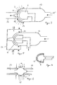
- domes 1 shows several domes 1, which are arranged next to one another in a grid on the base plate 2 of a recipient 3 for coating with a plasma pulse method.
- the domes 1 are sunk into corresponding depressions 4 in the base plate 2.
- the cover plate 5 of the recipient 3 is provided in accordance with the arrangement of the depressions 4 in the base plate 2 with an arrangement of displacement bodies 6 which are immersed in the cavities 8 delimited by the spherical cap surfaces 7 to be coated.
- Each displacement body 6 is provided for supplying the reaction gases with a central channel 9, which can be connected to a gas source, not shown in the figure.
- a plurality of gas outlet openings 10 are provided in the side walls of the recipient 3, through which the reaction gases depleted in layer material can be sucked off by means of a vacuum pump (not shown).
- the distance between a dome inner surface 7 and the side 11 of the associated displacement body 6 opposite this is dimensioned such that the particle formation taking place in the gas space between the two surfaces during a plasma discharge does not impair the layer quality.
- the means for generating the plasma zone in the recipient are known per se and are therefore not shown in the figure.
- the plasma can be excited capacitively in such a way that both the bottom and the top plate of the recipient consist of a metal and a voltage is applied between the two plates.
- both dielectric and metallic layers or mixed layers of dielectric and metallic materials can be deposited.
- the reaction gases are introduced through the displacement bodies 6 in a continuous gas flow into the cavities 8 delimited by the calotte inner surfaces 7 and the displacement bodies 6.
- the gas flow is deflected and guided along the surface to be coated laterally past the displacement body 6 and out of the cap 1 (the solid arrows in the figure indicate the gas flow direction).
- 3 layer material is deposited on the inner surface 7 of the spherical cap, the surface of the displacement body 6 and on the entire inner wall of the recipient.
- the time period between two plasma pulses and the gas mass flow are expediently coordinated with one another, as is customary in plasma pulse CVD processes, in such a way that the reaction space above the inner surface of the calotte is completely filled with fresh reaction gases before each plasma pulse.
- the device from FIG. 1 can be installed in an oven. It is easier to bring the substrates to the desired substrate temperature by means of a plasma pretreatment.
- Figures 2 and 3 show devices for coating individual domes. It can be seen that in each case a spherical cap 1 with a vessel 13 which is open on one side is joined to form a recipient 3. A sealing ring 14 located between the edges of the two vessel parts ensures a gas-tight connection.
- the device in FIG. 2 is suitable for coating a cap with a closed cap neck.
- the reaction gases are supplied through a gas inlet opening 15 in the vessel part 13 attached to the calotte.
- reaction gases are passed past the displacement body 6, along the surface to be coated to the spherical cap 12, deflected there and via the channel 16 in the displacement body 6 and the angled glass tube 17 which carries the displacement body 6 and which is connected to a vacuum pump (not shown). aspirated.
- a straight glass tube which is axially arranged in the vacuum vessel and which is melted into the vessel wall opposite the spherical cap can also be used to hold the displacement body.
- the gas supply can e.g. through gas inlet openings grouped around the melting point.
- the plasma is excited by irradiation with microwave energy.
- a waveguide 18 is placed on the spherical cap 1, the outer conductor 19 of which extends to the edge of the spherical cap and the inner conductor 20 ends immediately in front of the closed spherical cap neck 12.
- the plasma area can easily be limited to the reaction space 21 delimited by the calotte inner surface 7 and the end surface 11 of the displacement body 6.
- the plasma area extends in part up to channel 16 in the displacement body; the fact that only the reaction gases depleted of layer material are passed through this channel, a gradual clogging of the opening and the channel with layer material is largely avoided.
- Figure 3 shows a device for coating a cap with an open cap neck.
- the coating is carried out essentially analogously to the embodiment in FIG. 2.
- the consumed reaction gases are not discharged through the displacement body 6, but through the open cap neck 12.
- a glass tube 22, which is connected to a vacuum pump, is placed on the calotte 1 from the outside and by means of a Sealing ring 14 securely sealed against the outside.
- the plasma can be excited, for example, by irradiating microwave energy (see dashed arrows) by means of microwave antennas, not shown, which are grouped laterally around the calotte.
- the displacement body 6 in FIG. 2 does not necessarily have to have a central channel 16, but, as shown in FIG. 4, can be provided with small channels 23 ( ⁇ ⁇ 1 mm) distributed uniformly over the entire surface (e.g. frit).
- a second vacuum vessel 24 above the cap which is equipped with a gas that does not attack the cap material or in a plasma itself on the cap Coating takes part (for example O2), is applied. If the size of the leak remains unchanged, the amount of gas flowing into the cap 1 will be smaller, the smaller the pressure difference between the inside and outside of the cap.
- the pressure in the vacuum vessel 24 is set so high that no plasma is just ignited there during the plasma coating of the inner surface 7 of the cap (p ⁇ 50 to 100 mbar).
- the measure described above can be important if many domes are coated at the same time from the same gas supply system. Without this measure, the coating of all domes can be endangered by a single leak.
- FIG. 6 Two small, hemispherical domes 1 which are joined to form a vacuum vessel 25. Due to the spherical shape of the vacuum vessel 25, the same amount of gas is located above each surface element of the substrate surface. A uniform coating is therefore guaranteed even without a displacement body when using a plasma pulse CVD process. The volume limited by the two domes is small enough to rule out any impairment of the layer quality due to a homogeneous reaction in the gas space.
- the gas flow takes place through the open spherical necks 12, to which gas supply and discharge pipes 26, 27 are attached in a gas-tight manner, analogous to the device in FIG.
- the plasma can also be excited in a simple manner by irradiation of microwave energy by means of microwave antennas grouped laterally around the vacuum vessel.
- the coating and displacement bodies are in principle interchangeable.
- the cap to be coated can be brought into the place of the displacement body. It is only necessary to ensure that there is no layer material in the interior of the calotte in order to avoid an inner coating occurring simultaneously with the outer coating.
- the spherical cap can, for example, be part of a further vacuum vessel arranged in the recipient.
- the device shown in FIG. 2 is particularly suitable for the coating of domes in mass production, since the vacuum vessel has only a single seal. It is advisable to install several of the vessels attached to the spheres firmly next to one another, arranged in a grid. The gas supply as well as the connection to a vacuum pump can take place via common supply systems.
- the spherical caps are placed on the permanently installed vessel halves, a sealing ring is used if necessary, and the vacuum vessels formed in this way are evacuated.
- the plasma can be excited in a simple manner by irradiating microwave energy, for example by means of waveguides placed on the calottes from above.
- the vacuum vessels are ventilated, whereupon the coated domes can simply be lifted off and replaced with new substrates.
- An Viton O-ring on the polished tube end ensures a vacuum-tight connection between the tube and the calotte.
- the tube is made of a dielectric material, in this case borosilicate glass No. 8330 from Schott Glastechnike.
- the reaction gases can be led into the reaction space thus formed through a laterally melted glass tube with a 10 mm diameter.
- the used reaction gases are removed by a taper at the end of the pipe. Dimensions can be taken from Figure 2, which is carried out on a scale of 1: 1.
- the gas supply pipe is angled on the axis of the larger pipe; it is completed with an axially pierced teflon displacement body.
- the diameter of the hole is 5 mm, but this value is not very critical.
- the reaction gases can enter the reaction space through this bore.
- the displacement body is shaped so that the distance from its surface to the inner surface of the Ka-lotte is the same everywhere except for the area under the spherical cap, namely 7 mm.
- an O2 gas discharge is ignited in the reaction space formed by the spherical cap and displacement body in order to condition the inner surface of the spherical cap to be coated.
- the desired substrate temperature is set via the intensity and duration of this O2 gas discharge.
- the microwave energy is radiated from above onto the calotte by a microwave antenna.
- the microwave radiation is interrupted and the gas mixture for producing the first TiO2 layer is set.
- This gas mixture is first allowed to flow into the bypass line for about 0.5 min; then the mass flows are stationary. During this time, the calotte cools only slightly.
- the TiO2 layer is produced using the parameters:
- the microwave radiation is interrupted and the gas mixture for producing the first SiO2 layer is set; with a steady mass flow (see above), the SiO2 layer is produced.
- a dome made of borosilicate glass No. 8486 from Schott Glaswerke with a diameter of 50 mm lies in a recipient on the lower electrode of a 13.56 MHz plasma generator.
- the upper electrode is designed as a gas shower and displacement body. The distance between the displacement body and the inner surface of the substrate to be coated is 15 mm at each point on the substrate.
- the recipient is evacuated to 0.03 mbar and the dome is pretreated with an O2 gas discharge at this pressure. Then it is coated at the same pressure; a mass flow of 1 ml / 1 min TiCl4 and 35 ml O2 is set and a TiO2 layer is applied at an RF power of 50 W. Then a mass flow of 0.5 ml / min C6H18OSi2 (hexamethyldisiloxane) and 35 ml O2 is set and an SiO2 layer is applied at an RF power of 50 W.
- the layer thicknesses are adjusted according to known optical criteria so that the interference layer system is a cold light mirror.
Abstract
Es wird ein PCVD-Verfahren zur Herstellung eines auf der Innen- und/oder Außenfläche mit einem dielektrischen und/oder metallischen Schichtsystem versehenen annähernd kalottenförmigen Substrats (1), insbesondere eines Reflektors mit innenseitiger dielektrischer Kaltlichtspiegelbeschichtung, beschrieben. Des weiteren werden für die Durchführung des erfindungsgemäßen Verfahrens besonders geeignete Vorrichtungen beschrieben. Nach der Erfindung wird mit Hilfe eines Verdrängungskörpers (6) die Dicke der zu reagierenden Gasschicht über der zu beschichtenden Fläche so eingestellt, daß das Ausmaß der in der Gasschicht während einer Plasmaphase auftretenden Homogenreaktion ("Glasrußbildung") für die gewünschte Schichtqualität unschädlich bleibt. Durch Anwendung eines PCVD-Verfahrens können nahezu beliebig geformte, stark gewölbte, großflächige Substrate ohne komplizierte Substratbewegung auf ihrer Innen-und/oder Außenfläche mit einer gleichmäßigen Beschichtung von höchster optischer Qualität sowie mechanischer, thermischer und chemischer Stabilität versehen werden. Bei Anwendung eines PICVD-Verfahrens können durch entsprechende Formgebung des Verdrängungskörpers in an sich bekannter Weise vorgegebene axiale und azimutale Schichtdickenprofile aufgeprägt werden.A PCVD method for producing an approximately dome-shaped substrate (1) provided on the inner and / or outer surface with a dielectric and / or metallic layer system, in particular a reflector with an internal dielectric cold light mirror coating, is described. Furthermore, devices which are particularly suitable for carrying out the method according to the invention are described. According to the invention, the thickness of the gas layer to be reacted above the surface to be coated is adjusted with the aid of a displacement body (6) so that the extent of the homogeneous reaction ("glass soot formation") occurring in the gas layer during a plasma phase remains harmless for the desired layer quality. By using a PCVD process, almost any shape, strongly curved, large-area substrates can be provided with a uniform coating of the highest optical quality and mechanical, thermal and chemical stability on their inner and / or outer surface without complicated substrate movement. If a PICVD method is used, appropriate axial and azimuthal layer thickness profiles can be impressed by appropriate shaping of the displacement body in a manner known per se.
Description
Die Erfindung betrifft ein Plasma-CVD-Verfahren zur Herstellung eines auf der Innen- und/oder Außenfläche mit einem dielektrischen und/oder metallischen Schichtsystem versehenen annähernd kalottenförmigen Substrats, insbesondere eines Reflektors mit innenseitiger dielektrischer Kaltlichtspiegelbeschichtung, sowie eine Vorrichtung zur Durchführung des Verfahrens.The invention relates to a plasma CVD method for producing an approximately spherical substrate provided on the inner and / or outer surface with a dielectric and / or metallic layer system, in particular a reflector with an internal dielectric cold light mirror coating, and a device for carrying out the method.
Reflektoren bestehen in der Regel aus gewölbten, meist kalottenähnlich geformten Glassubstraten mit einer innenseitigen Reflexionsbeschichtung. Die Reflexionsbeschichtung kann aus einer metallischen Schicht oder aber, wenn ein spezieller spektraler Verlauf des Reflexionsgrades gewünscht ist, aus einem dielektrischen Schichtsystem bestehen. So kann man z.B. sog. Kaltlichtspiegel, wie z.B. Zahnarztspiegel, herstellen, welche nur im sichtbaren Spektralbereich einen hohen Reflexionsgrad aufweisen, für Wärmestrahlung hingegen durchlässig sind.As a rule, reflectors consist of curved, usually dome-shaped glass substrates with an internal reflective coating. The reflection coating can consist of a metallic layer or, if a special spectral course of the reflectance is desired, of a dielectric layer system. So you can e.g. so-called cold light mirrors, such as Manufacture dental mirrors, which only have a high degree of reflection in the visible spectral range, but are transparent to heat radiation.
Dielektrische Schichtsysteme mit einem selektiven spektralen Reflexionsvermögen bestehen i.a. aus alternierend übereinander angeordneten Schichten mit hohem und niedrigem Brechnungsindex. Wie solche Schichtsysteme im einzelnen aufzubauen sind, d.h. wieviele Schichtpaare übereinander anzuordnen sind und wie die Schichtdicken zur Erzielung eines gewünschten optischen Effekts zu bemessen sind, ist dem Fachmann bekannt und z.B. in H.A. Macleod, Thin Film Optical Filters, A. Hilger Ltd., London,beschrieben.Dielectric layer systems with a selective spectral reflectivity generally exist. from alternating layers of high and low refractive index. How to build up such layer systems in detail, i.e. how many pairs of layers are to be arranged one above the other and how the layer thicknesses are to be dimensioned to achieve a desired optical effect is known to the person skilled in the art and e.g. in H.A. Macleod, Thin Film Optical Filters, A. Hilger Ltd., London.
Üblicherweise werden die dielektrischen Schichtsysteme mittels Hochvakuumverfahren, wie z.B. Hochvakuumbedampfung, Kathodenzerstäubung oder Elektronenstrahlzerstäubung auf die Substrate aufgebracht. Um ohne komplizierte Bewegung eines stark gewölbten Substrats eine gleichmäßige Beschichtung der Substratinnenfläche zu erhalten, wird in der Regel ein " Gasstreuverfahren" (K. Steinfelder u.a., Vakuumtechnik 28 (1979), S. 48) eingesetzt. Dabei wird die Bedampfung unter erhöhtem Druck (etwa 10⁻³mbar) eines Zusatzgases durchgeführt, das die Aufgabe hat, die geradlinige Bewegung der Dampfpartikel von der Aufdampfquelle zum Substrat hin durch Vielfachstöße mit dem Zusatzgas zu unterbrechen, so daß keine Vorzugsrichtung in der Bewegung der Dampfpartikel mehr besteht. Nach diesem Verfahren können sog. "weiche" Schichtsysteme aus ZnS/MgF₂-Schichpaaren hergestellt werden, die aber griffempfindlich sind, und sog. "halbharte" Schichtsysteme aus Zns/SiO₂- und ZnS/Al₂O₃-Schichtpaaren, die zwar griffest, aber mechanisch nicht belastbar sind.The dielectric layer systems are usually produced using high vacuum processes, such as high vacuum evaporation, cathode sputtering or electron beam sputtering applied to the substrates. In order to obtain a uniform coating of the inner surface of the substrate without complicated movement of a strongly curved substrate, a "gas spreading method" is generally used (K. Steinfelder et al., Vacuum Technology 28 (1979), p. 48). The vaporization is carried out under increased pressure (about 10⁻³mbar) of an additional gas, which has the task of interrupting the linear movement of the vapor particles from the vapor deposition source to the substrate by multiple impacts with the additional gas, so that no preferred direction in the movement of the vapor particles more exists. According to this process, so-called "soft" layer systems made of ZnS / MgF₂ layer pairs can be produced, but which are sensitive to touch, and so-called "semi-hard" layer systems made of Zns / SiO₂ and ZnS / Al₂O₃ layer pairs, which are non-slip but mechanically are resilient.
Neben dem Gasstreuvertfahren ist noch ein weiteres Hochvakuumbedampfungsverfahren bekannt (H.K. Pulker, Coatings on Glass, Elsevier, Amsterdam 1984), bei welchem die Substrate zur Erzielung einer gleichmäßigen Beschichtung während des Bedampfens auf Planetenhalterungen eine zweifache Rotationsbewegung ausführen. Mit den oben beschriebenen Schichtsystemen versehene Reflektoren (Durchmesser am Kalottenfuß ca. 5 cm) haben jedoch den Nachteil, daß sie bei hoher Luftfeuchtigkeit früh ausfallen und thermisch nicht stabil genug sind, um der in der Regel hohen Wärmeentwicklung der üblicherweise eingesetzten Halogenglühlampen auch bei elektrischen Leistungen von über 50 W noch standzuhalten.In addition to gas spreading, another high vacuum evaporation method is known (H.K. Pulker, Coatings on Glass, Elsevier, Amsterdam 1984), in which the substrates perform a double rotational movement in order to achieve a uniform coating during the evaporation on planetary holders. However, reflectors provided with the layer systems described above (diameter at the base of the dome approx. 5 cm) have the disadvantage that they fail early in the case of high atmospheric humidity and are not thermally stable enough to withstand the generally high heat development of the halogen bulbs usually used, even with electrical outputs withstand more than 50 W.
Mit Elektronenstrahlverdampfung im Hochvakuum lassen sich SiO₂/TiO₂-Schichtsysteme herstellen, die bezüglich ihrer mechanischen, chemischen und thermischen Belastbarkeit hohen Anforderungen genügen und daher üblicherweise als sog. "harte" Schichtsysteme bezeichnet werden. Aufgrund der schwierigeren Herstellung (z.B. komplizierte Substratbewegung, Substratheizung) sind diese Schichtsysteme auf stark gewölbten Substraten jedoch um ein mehrfaches teurer als die weichen Schichten.With electron beam evaporation in a high vacuum, SiO₂ / TiO₂ layer systems can be produced which meet high requirements with regard to their mechanical, chemical and thermal resilience and are therefore usually referred to as so-called "hard" layer systems. Due to the more difficult production (e.g. complicated substrate movement, substrate heating), these layer systems on highly curved substrates are several times more expensive than the soft layers.
Der Erfindung liegt die Aufgabe zugrunde, ein einfach durchführbares und kostengünstiges Verfahren bereitzustellen, welches geeignet ist, stark gewölbte, großflächige Substrate, wie z.B. Kalotten, auf der Innen- und/oder Außenfläche mit einem dielektrischen und/oder metallischen Schichtsystem von höchster optischer Qualität und mechanischer, thermischer sowie chemischer Stabilität zu versehen. Insbesondere soll das Verfahren zur Herstellung von Reflektoren mit innenseitiger dielektrischer Kaltlichtspiegelbeschichtung geeignet sein.The invention has for its object to provide a simple to carry out and inexpensive method which is suitable to provide strongly curved, large-area substrates, such as spherical caps, on the inner and / or outer surface with a dielectric and / or metallic layer system of the highest optical quality and mechanical, thermal and chemical stability. In particular, the method should be suitable for producing reflectors with an internal dielectric cold light mirror coating.
Eine weitere Aufgabe der Erfindung besteht darin, eine für die Durchführung des Verfahrens geeignete Vorrichtung zu finden.Another object of the invention is to find a device suitable for carrying out the method.
In bezug auf das Verfahren wird die Aufgabe durch das in den Patentansprüchen 1 oder 5 beschriebene Verfahren gelöst. In den Patentansprüchen 6, 7 und 11 werden bevorzugte Vorrichtungen zur Durchführung des erfindungsgemäßen Verfahrens beschrieben.With regard to the method, the object is achieved by the method described in
Die üblicherweise zur Innenbeschichtung rohrförmiger Glasrohlinge zur Herstellung von Lichtleitfasern eingesetzten Plasma-CVD-Verfahren sind an sich bekannt. Eine grundlegende Beschreibung ist z.B. in Journal of Optical Communications, vol.8 (1987), S. 122, zu finden.The plasma CVD processes usually used for the inner coating of tubular glass blanks for the production of optical fibers are known per se. A basic description is e.g. in Journal of Optical Communications, vol. 8 (1987), p. 122.
Von diesen Verfahren ist insbesondere das Plasmaimpuls-CVD-Verfahren (s. hierzu z.B. Journal of Optical Communications, vol.8 (1987), S. 130) zur Herstellung dielektrischer Schichtsysteme mit definierten optischen Eigenschaften geeignet. Mittels des Plasmaimpuls-CVD-Verfahrens lassen sich sehr dünne gleichmäßige Schichten bis hin zu monomolekularen Schichten auf Substraten erzeugen.Of these processes, the plasma pulse CVD process (see, for example, Journal of Optical Communications, vol. 8 (1987), p. 130) is particularly suitable for producing dielectric layer systems with defined optical properties. The plasma pulse CVD process can be used to produce very thin, even layers down to monomolecular layers on substrates.
Der Begriff Plasma-CVD-Verfahren schließt im Sinne dieser Erfindung das Plasmaimpuls-CVD-Verfahren mit ein. Das Plasmaimpuls-CVD-Verfahren wird sogar bevorzugt verwendet.For the purposes of this invention, the term plasma CVD method includes the plasma pulse CVD method. The plasma pulse CVD method is even preferred.
Die mittels Plasma-CVD-Verfahren hergestellten Schichten zeichnen sich nicht nur durch eine sehr hohe optische Qualität aus, sie sind darüber hinaus auch noch chemisch, mechanisch und thermisch außerordentlich stabil. Diese vorteilhaften Eigenschaften, verdanken sie der Tatsache, daß sie hinsichtlich der Stöchiometrie und Morphologie praktisch die Eigenschaften von Massivmaterial aufweisen.The layers produced by means of plasma CVD processes are not only characterized by a very high optical quality, they are also extremely chemically, mechanically and thermally stable. They owe these advantageous properties to the fact that they have practically the properties of solid material in terms of stoichiometry and morphology.
Die Erfindung macht sich die Tatsache zunutze, daß die Plasma-CVD-Verfahren an sich hervorragend zur Beschichtung kompliziert geformter Teile geeignet sind, da sie eine hohe Streuwirkung besitzen. Es ist bei diesen Verfahren nicht nötig, die Substrate zur Erzielung einer gleichmäßigen Beschichtung zu drehen oder in sonst irgendeiner Weise zu bewegen. Trotz dieses Vorteils konnten Plasma-CVD-Verfahren bisher lediglich zur Beschichtung kleinflächiger, stark gewölbter Substrate eingesetzt werden.The invention takes advantage of the fact that the plasma CVD processes are in themselves excellently suitable for coating complicated-shaped parts, since they have a high scattering effect. With these methods, it is not necessary to rotate the substrates or to move them in any other way in order to achieve a uniform coating. Despite this advantage, plasma CVD processes could previously only be used to coat small, strongly curved substrates.
In der EP-PS 0 017 296 wird z.B. ein Plasma-CVD-Verfahren zur Herstellung kugelförmiger Mikrolinsen beschrieben, wonach eine Glasplatte zur Aufnahme der Linsen mit ca. 35 µ m tiefen Vertiefungen versehen wird. Bei der anschließend erfolgenden Beschichtung wird über der gesamten Glasplatte eine Plasmazone erzeugt, welche sich bis in die Vertiefungen hinein erstreckt. Dies hat zur Folge, daß das Schichtmaterial nicht nur auf der Oberfläche der Glasplatte, sondern auch in die Vertiefungen abgeschieden wird, wobei in an sich bekannter Weise durch Anderung der Reaktionsgaszusammensetzung während der Beschichtung ein gewünschtes Brechzahlprofil in der abgeschiedenen Schicht erzeugt werden kann. Die Beschichtung wird nach der obengenannten Druckschrift erst dann gestoppt, wenn die Vertiefungen vollständig mit Schichtmaterial aufgefüllt sind. In weiteren Verfahrensschritten (Planschleifen der Oberfläche und Verkleben mit einer weiteren beschichteten Platte, so daß jeweils zwei Halbkugeln zu einer Kugel zusammengesetzt werden) werden aus der beschichteten Glasplatte in Glasrahmen eingebettete Kugellinsen hergestellt.In EP-PS 0 017 296 e.g. describes a plasma CVD process for the production of spherical microlenses, after which a glass plate for receiving the lenses is provided with depressions approximately 35 μm deep. During the subsequent coating process, a plasma zone is created over the entire glass plate, which extends into the recesses. This has the consequence that the layer material is deposited not only on the surface of the glass plate, but also in the depressions, a desired refractive index profile being able to be produced in the deposited layer in a manner known per se by changing the reaction gas composition during the coating. According to the above-mentioned document, the coating is only stopped when the depressions are completely filled with layer material. In further process steps (surface grinding of the surface and gluing with a further coated plate so that two hemispheres are put together to form a ball), ball lenses embedded in glass frames are produced from the coated glass plate.
Das oben beschriebene Verfahren läßt sich jedoch nicht auf die Beschichtung stark gewölbter Substrate mit größeren Abmessungen (⌀ ≳ 5 mm am Kalottenfuß), wie z.B. Reflektoren mit kalottenähnlich geformter Reflektorfläche, welche für die gebräuchlichsten Anwendungen in der Regel am Kalottenfuß einen Durchmesser von wenigstens 20 mm besitzen, übertragen, da die Dicke einer zur Beschichtung geeigneten Plasmazone über der zu beschichtenden Fläche üblicherweise auf einige 10 mm beschränkt ist und das Plasma somit nicht, wie zur Erzeugung einer gleichmäßigen Innen- bzw.However, the method described above cannot be applied to the coating of strongly curved substrates with larger dimensions (⌀ ≳ 5 mm on the dome base), such as reflectors with a dome-shaped reflector surface, which for the most common applications usually have a diameter of at least 20 mm on the dome base possess, transferred, since the thickness of a plasma zone suitable for coating is usually limited to a few 10 mm above the surface to be coated and the plasma is therefore not, as is the case for producing a uniform interior or
Außenbeschichtung erforderlich, den gesamten Körper auf der zu beschichtenden Seite einschließen kann. Bei größeren Dicken des Plasmabereichs steigt die Wahrscheinlichkeit, daß sich nicht nur an der Grenzfläche Substrat/Gasraum, sondern im gesamten Gasraum in einer sog. Homogenreaktion Partikel bilden, welche sich dann als Glasruß auf der Substratoberfläche absetzen und in die abgeschiedenen Schichten miteingebaut werden. Dadurch wird die Schichtqualität so stark verschlechtert, daß die Schichten unbrauchbar werden.External coating required, can include the entire body on the side to be coated. With greater thicknesses of the plasma area, the probability increases that particles form not only at the substrate / gas space interface, but in the entire gas space in a so-called homogeneous reaction, which then settle as soot on the substrate surface and are incorporated into the deposited layers. As a result, the layer quality deteriorates so much that the layers become unusable.
Das erfindungsgemäße Verfahren wird im folgenden am Beispiel der insbesondere für die Anwendung interessanten Innenbeschichtung von Substraten, z.B. zur Herstellung von Reflektoren, beschrieben. Die nachfolgenden Ausführungen sind jedoch ohne wesentliche Einschränkungen auch für die Außenbeschichtung von Substraten nach dem erfindungsgemäßen Verfahren gültig. Insbesondere können die für die Innenbeschichtung beschriebenen Vorrichtungen in einfacher Weise durch die umgekehrte Anordnung der Substrate und eine entsprechende Formgebung der Verdrängungskörper auf die Außenbeschichtung umgerüstet werden. Eine Ausnahme stellt lediglich das in Patentanspruch 5 beschriebene Verfahren dar, das ausschließlich zur Innenbeschichtung geeignet ist.The method according to the invention is described below using the example of the inner coating of substrates, which is particularly interesting for the application, e.g. for the production of reflectors. However, the following statements are also valid for the external coating of substrates by the method according to the invention without significant restrictions. In particular, the devices described for the inner coating can be converted to the outer coating in a simple manner by the reverse arrangement of the substrates and a corresponding shaping of the displacement bodies. The only exception is the method described in
Nach der Erfindung wird zur Innenbeschichtung eines annähernd kalottenförmigen Substrats, im folgenden auch Kalotte genannt, in dem von dem gewölbten Substrat begrenzten, halbseitig offenen Hohlraum ein sog. Verdrängungskörper beabstandet und verschiebbar zu der zu beschichtenden Fläche angeordnet. Mit Hilfe des Verdrängungskörpers stellt man die Dicke der zu reagierenden Gasschicht über der zu beschichtenden Fläche so ein, daß das Ausmaß der in der Gasschicht während einer Plasmaphase auftretenden Homogenreaktion ("Glasrußbildung") für die gewünschte Schichtqualität unschädlich bleibt.According to the invention, a so-called displacement body is spaced apart and displaceably arranged in relation to the surface to be coated, in order to coat an approximately dome-shaped substrate, hereinafter also called a dome, in the cavity that is open on one side and is delimited by the curved substrate. With the aid of the displacement body, the thickness of the gas layer to be reacted over the surface to be coated is adjusted so that the extent of the homogeneous reaction ("glass soot formation") occurring in the gas layer during a plasma phase remains harmless for the desired layer quality.
Für die Herstellung dielektrischer Interferenzschichtsysteme für Reflektoren ist die Schichtqualität in der Regel ausreichend gut, wenn der Abstand 20 mm nicht übersteigt. Ein Abstand von weniger als 2 mm sollte dagegen nicht unterschritten werden, da sonst zu hohe Anforderungen an die Positioniergenauigkeit des Verdrängungskörpers gestellt werden.For the manufacture of dielectric interference layer systems for reflectors, the layer quality is generally sufficiently good if the distance does not exceed 20 mm. On the other hand, a distance of less than 2 mm should not be undercut, since otherwise the positioning accuracy of the displacer will have to be too high.
Zur Durchführung der Beschichtung werden in an sich bekannter Weise die Reaktionsgase in den Reaktionsraum eingeleitet und das schichtbildende Plasma gezündet.To carry out the coating, the reaction gases are introduced into the reaction space in a manner known per se and the layer-forming plasma is ignited.
Als Reaktionsgase werden bei PCVD-Verfahren üblicherweise Metallchloride, metallorganische Verbindungen, Sauerstoff, Stickstoff und Ammoniak eingesetzt. Für die Abscheidung der für Reflektoren mit Kaltlichtverspiegelung geeigneten "harten" SiO₂/TiO₂-Schichtsysteme können neben Sauerstoff z.B. SiCl₄ und TiCl₄ als Reaktionsgase verwendet werden. Die Verwendung von SiCl₄ hat jedoch den Nachteil, daß, um den Einbau von Chlor in die Schichten zu verhindern, hohe Substrattemperaturen erforderlich sind. Für die Beschichtung von Kalotten nach dem erfindungsgemäßen Verfahren wird die Verwendung von Hexamethyldisiloxan anstelle des SiCl₄ bevorzugt, da damit die Notwendigkeit für hohe Substrattemperaturen entfällt und das Verfahren wirtschaftlicher arbeitet.Metal chlorides, organometallic compounds, oxygen, nitrogen and ammonia are usually used as reaction gases in PCVD processes. For the deposition of the "hard" SiO₂ / TiO₂ layer systems suitable for reflectors with cold light reflecting, in addition to oxygen e.g. SiCl₄ and TiCl₄ can be used as reaction gases. However, the use of SiCl₄ has the disadvantage that high substrate temperatures are required to prevent the incorporation of chlorine into the layers. For the coating of domes by the process according to the invention, the use of hexamethyldisiloxane instead of SiCl₄ is preferred, since this eliminates the need for high substrate temperatures and the process works more economically.
Für die Anregung des Plasmas kommen alle hierfür bekannten Methoden, wie z.B. Hochfrequenz-, Niederfrequenz-, Mikrowellen-, Gleichspannungs-, oder gepulste Gleichspannungsanregung in Frage. Die Hoch- und Niederfrequenzanregung kann sowohl kapazitiv als auch induktiv erfolgen.All methods known for this purpose are used to excite the plasma, e.g. High-frequency, low-frequency, microwave, direct voltage, or pulsed direct voltage excitation in question. The high and low frequency excitation can take place both capacitively and inductively.
Bei dem erfindungsgemäßen Verfahren wird die Mikrowellenanregung bevorzugt. Die Mikrowellenanregung hat den Vorteil, daß die Gefahr der Strahlenschädigung der abgeschiedenen Schichten gering ist, daß die für einen Prozeß notwendige Plasmaleistung mit zunehmender Frequenz sinkt, daß der Einkoppelwirkungsgrad hoch ist und Mikrowellenplasmen über weite Druckbereiche (etwa 10⁻³ bis 50 mbar) betrieben werden können.Microwave excitation is preferred in the method according to the invention. Microwave excitation has the advantage that the risk of radiation damage to the deposited layers is low, that the plasma power required for a process decreases with increasing frequency, that the coupling efficiency is high and that microwave plasmas are operated over wide pressure ranges (approx. 10⁻³ to 50 mbar) can.
Neben diesen mehr allgemeinen, für jedes PCVD-Verfahren zutreffenden Vorteilen, ist die Verwendung eines Mikrowellenplasmas für das erfindungsgemäße Verfahren noch dadurch besonders günstig, daß durch die Beschränkung des Plasmabereichs auf möglichst kleine Volumina weniger leistungsstarke, preiswerte Bauteile, wie z.B. Magnetrons, als Mikrowellengeneratoren eingesetzt werden können. So kann z.B. bei der Beschichtung kleiner Kalotten mit einem Durchmesser am Kalottenfuß von nicht mehr als 50 mm die von einem einzigen Magnetron gelieferte elektrische Leistung (100 W) ausreichen, um in wenigstens 4 Kalotten die Plasmabereiche zu zünden und aufrechtzuerhalten.In addition to these more general advantages that apply to every PCVD method, the use of a microwave plasma for the method according to the invention is particularly advantageous in that less powerful, inexpensive components, such as magnetrons, are used as microwave generators by restricting the plasma range to the smallest possible volume can be. For example, when coating small calottes with a diameter on the calotte base of no more than 50 mm the electrical power (100 W) supplied by a single magnetron is sufficient to ignite and maintain the plasma areas in at least 4 spherical caps.
Für die Innenbeschichtung von Reflektoren werden bevorzugt Glassubstrate eingesetzt. Kunststoffsubstrate können zwar prinzipiell ebensogut nach dem erfindungsgemäßen Verfahren beschichtet werden, die meisten Kunststoffe sind jedoch aufgrund ihrer i.a. geringen thermischen Belastbarkeit für die Verwendung als Reflektoren weniger geeignet. Darüber hinaus ist die Haftung der oben beschriebenen Schichtsysteme insbesondere bei Temperaturbelastung auf Glas besser als auf Kunststoff.Glass substrates are preferably used for the inner coating of reflectors. In principle, plastic substrates can be coated just as well by the method according to the invention, but most plastics are, due to their i.a. low thermal resistance less suitable for use as reflectors. In addition, the adhesion of the layer systems described above is better in particular when exposed to temperature on glass than on plastic.
Das erfindungsgemäße Verfahren eignet sich wegen der einfacheren Positionierung des Verdrängungskörpers insbesondere für die Beschichtung stark gewölbter Substrate mit rotationssymmetrischer Gestalt, wie z.B. Kalotten _ oder ellipsoidisch oder parabolisch geformte Körper. Bei entsprechender Formgebung des Verdrängungskörpers können aber ohne weiteres auch unregelmäßig geformte Substrate, z.B. langgestreckte gewölbte Substrate, wie sie z.B. zur Herstellung von Zahnarztspiegeln verwendet werden, beschichtet werden.Because of the simpler positioning of the displacement body, the method according to the invention is particularly suitable for coating strongly curved substrates with a rotationally symmetrical shape, such as Dome _ or ellipsoidal or parabolic shaped bodies. With a corresponding shape of the displacement body, irregularly shaped substrates, e.g. elongated curved substrates, such as those e.g. used to manufacture dental mirrors, are coated.
Das erfindungsgemäße Verfahren erlaubt, mehrere Substrate gleichzeitig in einem Rezipienten zu beschichten. Zur Beschränkung des Reaktionsraumvolumens ist es dabei zweckmäßig, die Kalotten mit ihren Öffnungen dem Inneren des Reaktionsraums zugewandt in entsprechende Vertiefungen in einer Substrathalterung oder z.B. in der Bodenplatte des Rezipienten zu versenken. Die Deckplatte des Rezipienten kann dann vorteilhafterweise mit einer der Anordnung der Substrate entsprechenden Anordnung von Ausbuchtungen versehen sein, welche sich beim Schließen des Rezipienten als Verdrängungskörper in die von den Substraten begrenzten Hohlräume einsenken. Bevorzugt werden jedoch die Verdrängungskörper zur Einstellung der Dicke der zu reagierenden Gasschicht mittels geeigneter Halterungen zu den zu beschichtenden Fläche im Abstand veränderbar angeordnet. Die frischen und die an Schichtmaterial verarmten Reaktionsgase können bei dieser Anordnung z.B. durch in den Seitenwänden des Rezipienten befindliche Gasein-und -auslaßöffnungen, welche mit einer oder mehreren Gasquellen bzw. einer Vakuumpumpe außerhalb des Rezipienten verbunden sind, in einem kontinuierlichen Gasstrom, im wesentlichen parallel zu den zu beschichtenden Flächen, durch den Rezipienten geführt werden.The method according to the invention allows several substrates to be coated simultaneously in one recipient. To limit the reaction space volume, it is expedient to sink the domes with their openings facing the interior of the reaction space into corresponding recesses in a substrate holder or, for example, in the base plate of the recipient. The cover plate of the recipient can then advantageously be provided with an arrangement of bulges which corresponds to the arrangement of the substrates and which, when the recipient is closed, sink as a displacement body into the cavities delimited by the substrates. However, the displacement bodies for adjusting the thickness of the gas layer to be reacted are preferably arranged such that they can be spaced apart from the surface to be coated by means of suitable holders. In this arrangement, the fresh and the depleted reaction gases in the layer material can be caused, for example, by gas inlet and outlet openings located in the side walls of the recipient, which are connected to one or more gas sources or a vacuum pump outside the recipient, are passed through the recipient in a continuous gas stream, essentially parallel to the surfaces to be coated.
Die oben beschriebene Anordnung ist bei kapazitiver Anregung, wobei die Deck- und Bodenplatte des Rezipienten aus einem Metall bestehen, insbesondere auch zum Abscheiden metallischer Schichten oder Mischschichten aus einem Metall und einem Dielektrikum, wobei z.B. der Übergang von einer rein metallischen zu einer rein dielektrischen Schicht auch kontinuierlich erfolgen kann, geeignet.The arrangement described above is for capacitive excitation, the top and bottom plates of the recipient being made of a metal, in particular also for depositing metallic layers or mixed layers of a metal and a dielectric, e.g. the transition from a purely metallic to a purely dielectric layer can also take place continuously.
Zur Herstellung von Reflektoren mit Kaltlichtspiegeln werden in der Regel durch Pressen geformte Glassubstrate verwendet, welche auf ihrer äußeren gewölbten Oberfläche bereits mit Lampenstutzen, den sog. Kalottenhälsen, für die elektrischen Anschlüsse versehen sind. Vor der Beschichtung werden die Substrate einem Reinigungsprozeß unterzogen, wobei bestimmte Reinigungsverfahren, z.B solche, bei denen die Kalotte von einer Reinigungsflüssigkeit durchströmt wird, es erforderlich machen, den von der Formgebung herrührenden Verschluß am Kalottenhals nach dem Pressen zu entfernen.For the manufacture of reflectors with cold-light mirrors, glass substrates are generally used, which are already provided with lamp sockets, the so-called dome necks, for the electrical connections on their outer curved surface. Before the coating, the substrates are subjected to a cleaning process, whereby certain cleaning methods, e.g. those in which a cleaning liquid flows through the cap, make it necessary to remove the closure on the cap neck resulting from the shaping after the pressing.
Bei der Beschichtung dieser sog. offenen Kalotten kann die Öffnung im Kalottenhals vorteilhaft dazu genutzt werden, jede einzelne Kalotte während des Abscheideprozesses separat mit frischen Reaktionsgasen zu versorgen. Das sonst üblicherweise infolge der zunehmenden Verarmung der Reaktionsgase an Schichtmaterial in Gasflußrichtung auftretende Schichtdickengefälle von Kalotte zu Kalotte wird dadurch vermieden. Die verbrauchten Reaktiongase können durch Öffnungen in den Seitenwänden des Rezipienten abgezogen werden.When coating these so-called open spherical caps, the opening in the spherical cap neck can advantageously be used to supply each individual spherical cap separately with fresh reaction gases during the deposition process. The layer thickness gradient from dome to dome, which usually occurs as a result of the increasing depletion of the reaction gases on layer material in the gas flow direction, is thereby avoided. The used reaction gases can be drawn off through openings in the side walls of the recipient.
Bei geschlossenen Kalotten empfiehlt es sich, jeder einzelnen Kalotte die frischen Reaktionsgase durch entsprechende Kanäle in den Verdrängungskörpern zuzuleiten. Aber auch die offenen Kalotten können auf diese Weise mit frischen Reaktionsgasen versorgt werden.In the case of closed spherical caps, it is advisable to feed the fresh reaction gases to each individual spherical cap through appropriate channels in the displacement bodies. The open domes can also be supplied with fresh reaction gases in this way.
Bei der gleichzeitigen Beschichtung mehrerer Substrate in einem Rezipienten läßt es sich nicht vermeiden, daß neben den Substraten auch die Wände des Rezipienten mitbeschichtet werden. Dies hat nicht nur einen höheren Verbrauch an Schichtmaterial zur Folge, sondern auch den Nachteil, daß der Rezipient je nach Schichtdicke und Material bei einem Beschichtungsprozeß und je nach den Anforderungen an die Schichtqualität einer aufwendigen Reinigungsprozedur unterzogen werden muß. Diese Reinigung läßt sich nicht immer so gründlich durchführen, daß nicht doch noch Reste der alten Beschichtungen an den Wänden haftenbleiben. Diese Reste können sich im Laufe weiterer Beschichtungsverfahren u. U. von den Wänden lösen und in Form kleiner Partikel auf die zu beschichtenden Substratinnenflächen absetzen und deren Beschichtungen damit unbrauchbar machen.When coating several substrates in one container at the same time, it cannot be avoided that the walls of the container are also coated in addition to the substrates. This not only results in a higher consumption of layer material, but also the disadvantage that the recipient, depending on the layer thickness and material, has to be subjected to a complex cleaning procedure in a coating process and depending on the requirements for the layer quality. This cleaning cannot always be carried out so thoroughly that the remains of the old coatings do not stick to the walls. These residues can u. U. detach from the walls and settle in the form of small particles on the inner surfaces of the substrate to be coated, making their coatings unusable.
Um diese Probleme zu vermeiden, wird in einer bevorzugten Verfahrensvariante jedes Substrat einzeln beschichtet und dabei selbst als Teil des Vakuumgefäßes verwendet. Hierzu wird das gewölbte Substrat mit einem entsprechend dimensionierten halbseitig offenen Gefäß, z.B. mit einem an seinem einen Ende zugeschmolzenen Glasrohr, zu einem geschlossenen Gefäß zusammengesetzt und gasdicht verbunden. Für die gasdichte Verbindung reicht es, sofern beide Teile aus Glas bestehen, i.a. aus, die polierten Ränder einfach aneinanderzusetzen und das Gefäß zu evakuieren. Die Abdichtung wird noch verbessert, wenn man zwischen die Ränder der beiden Teilgefäße O-Ringe aus Fluorelastomeren oder Silikongummi legt. Die Verwendung von Dichtungsringen aus organischem Material ist aber auf Substrattemperaturen von maximal ca. 200 °C beschränkt, wobei Fluorkohlenstoffharze und Fluorelastomere Dauertemperaturen bis zu 260 °C widerstehen können.In order to avoid these problems, each substrate is coated individually in a preferred process variant and is used itself as part of the vacuum vessel. For this purpose, the curved substrate is covered with a suitably dimensioned half-open vessel, e.g. with a glass tube melted at one end, assembled into a closed vessel and connected gas-tight. For the gas-tight connection, if both parts are made of glass, it is generally sufficient just put the polished edges together and evacuate the vessel. The seal is further improved if you place O-rings made of fluoroelastomers or silicone rubber between the edges of the two partial vessels. However, the use of sealing rings made of organic material is limited to a maximum substrate temperature of approx. 200 ° C, whereby fluorocarbon resins and fluoroelastomers can withstand continuous temperatures of up to 260 ° C.
Während einer Beschichtung wird bei der oben beschriebenen Verfahrensvarianten der Plasmabereich zweckmäßigerweise auf den Kalotteninnenraum beschränkt. Das an die Kalotte angesetzte Gefäßteil wird dadurch nur geringfügig mitbeschichtet und kann entweder ohne oder erforderlichenfalls nach einer einfachen Reinigungsprozedur zur Beschichtung weiterer Kalotten wiederverwendet werden. Da mit jedem Substratwechsel ohnehin jeweils ein Teil des Vakuumgefäßes erneuert wird, ist der Reinigungsaufwand im Vergleich zur Beschichtung eines in einem Rezipienten befindlichen Substrats erheblich herabgesetzt. Um völlig sicherzugehen, daß die Beschichtung nicht doch noch durch sich von der Wand des wiederverwendeten Gefäßteils lösende Beschichtungspartikel beeinträchtigt wird, wird das Vakuumgefäß zweckmäßigerweise so angeordnet, daß sich die Kalotte bei der Beschichtung möglichst senkrecht über dem wiederverwendeten Gefäßteil befindet.In the case of the process variants described above, the plasma area is expediently limited to the interior of the cap during a coating. The part of the vessel attached to the spherical cap is thus only slightly coated and can be reused for coating further spherical caps either without or, if necessary, after a simple cleaning procedure. Since a portion of the vacuum vessel is replaced each time the substrate is changed, the cleaning effort is considerably reduced in comparison to the coating of a substrate in a recipient. To be completely sure that the coating If the coating particles detachable from the wall of the reused vessel part are not impaired, the vacuum vessel is expediently arranged in such a way that the cap is as vertical as possible above the reused vessel part during the coating.
Der Verdrängungskörper ist zweckmäßigerweise an der Wand des an das Substrat angesetzten Gefäßes beabstandet und verschiebbar zu der zu beschichtenden Fläche gehaltert, z.B. mittels eines in die Gefäßwand eingeschmolzenen Glasrohres, welches mit seinem freien, den Verdrängungskörper tragenden Ende auf den Substratinnenraum hin weist. Der Verdrängungskörper kann z.B. auf das Ende des Glasrohres aufgeschraubt oder aufgesteckt sein. Dies hat den Vorteil, daß bei einem Substratwechsel der Abstand des Verdrängungskörpers zu der Substratinnenfläche leicht eingestellt werden kann.The displacement body is expediently spaced on the wall of the vessel attached to the substrate and is slidably supported to the surface to be coated, e.g. by means of a glass tube melted into the vessel wall, which, with its free end carrying the displacement body, points towards the interior of the substrate. The displacement body can e.g. be screwed or attached to the end of the glass tube. This has the advantage that the distance between the displacement body and the inner surface of the substrate can be easily adjusted when the substrate is changed.
Je nachdem, ob eine Kalotte mit einem geschlossenen oder einem offenen Kalottenhals beschichtet werden soll, ergeben sich für die Führung der Reaktionsgase unterschiedliche Verhältnisse.Depending on whether a dome is to be coated with a closed or an open dome neck, there are different conditions for the guidance of the reaction gases.
Bei der Beschichtung einer geschlossenen Kalotte werden die Reaktionsgase durch eine Gasein- oder -auslaßöffnung in dem an die Kalotte angesetzten Gefäßteil und eine weitere Gasaus- oder -einlaßöffnung in dem Verdrängungskörper auf der der zu beschichtenden Fläche zugewandten Seite, welche über einen Kanal im Verdrängungskörper mit einer Gasquelle bzw. Vakuumpumpe außerhalb des Vakuumgefäßes verbunden ist, in einem kontinuierlichen Gasstrom an der zu beschichtenden Fläche entlanggeführt. Vorteilhafterweise wird dazu der Verdrängungskörper so gehaltert, daß sich der Kanal in dem Verdrängungskörper in dem nach außen führenden, den Verdrängungskörper tragenden Glasrohr fortsetzt.When coating a closed calotte, the reaction gases are passed through a gas inlet or outlet opening in the vessel part attached to the calotte and a further gas outlet or inlet opening in the displacement body on the side facing the surface to be coated, which side also has a channel in the displacement body a gas source or vacuum pump is connected outside the vacuum vessel, guided in a continuous gas flow along the surface to be coated. For this purpose, the displacement body is advantageously held in such a way that the channel in the displacement body continues in the glass tube leading to the outside and carrying the displacement body.
Es ist strömungstechnisch günstig, die Gasflußrichtung so zu wählen, daß die frischen Reaktionsgase durch den Kanal im Verdrängungskörper in den Reaktionsraum eingeleitet und die an Schichtmaterial verarmten Reaktionsgase durch eine Gasauslaßöffnung in dem an die Kalotte angesetzten Gefäßteil abgeführt werden. Bei der umgekehrten Gasflußrichtung ist es wegen des Druckabfalls in der Düse des Verdrängungskörpers schwierig, in dem Rezipienten den für die Beschichtung erforderlichen, niedrigen Druck aufrechtzuerhalten.From the point of view of flow technology, it is favorable to choose the gas flow direction so that the fresh reaction gases are introduced into the reaction chamber through the channel in the displacement body and the reaction gases depleted in layer material are discharged through a gas outlet opening in the vessel part attached to the calotte. With the reverse direction of gas flow it is difficult to maintain in the recipient the low pressure required for coating due to the pressure drop in the nozzle of the displacer.
Die oben beschriebene Gasflußrichtung empfiehlt sich insbesondere auch dann, wenn Substrate mit nicht rotationssymmetrischer Gestalt beschichtet werden sollen. Da es in diesem Fall sehr schwierig ist, an jeder Stelle der zu beschichtenden Fläche gleiche Strömungsverhältnisse für die Reaktionsgase zu schaffen, ist es zur Erzielung einer gleichmäßigen Beschichtung zweckmäßig, die frischen Reaktionsgase über eine Vielzahl von Gaseinlaßöffnungen, welche gleichmäßig über die der zu beschichtenden Fläche gegenübertiegende Stirnfläche des Verdrängungskörpers verteilt sind und über einen zentralen Kanal im Verdrängungskörper mit einer Gasquelle außerhalb des Vakuumgefäßes verbunden sind, in den Reaktionsraum einzuleiten.The gas flow direction described above is also particularly recommended when substrates with a non-rotationally symmetrical shape are to be coated. In this case, since it is very difficult to create the same flow conditions for the reaction gases at every point of the surface to be coated, it is expedient to achieve a uniform coating, the fresh reaction gases through a plurality of gas inlet openings, which are uniform over that of the surface to be coated opposite end face of the displacement body are distributed and connected to a gas source outside the vacuum vessel via a central channel in the displacement body to be introduced into the reaction space.
Besonders einfach werden die Verhältnisse bei der Beschichtung von offenen Kalotten. In diesem Fall muß der Gasstrom nicht durch den Verdrängungskörper geleitet werden, sondern es ist möglich, den offenen Kalottenhals selbst an geeignete Zuleitungen zu einer Gasquelle bzw. einer Vakuumpumpe anzuschließen. Für die Gasflußrichtung gibt es bei dieser Ausführungsform keine Vorzugsrichtung.The situation becomes particularly simple when coating open domes. In this case, the gas flow does not have to be passed through the displacement body, but it is possible to connect the open cap neck itself to suitable feed lines to a gas source or a vacuum pump. There is no preferred direction for the gas flow direction in this embodiment.
Es kann vorteilhaft sein, bei "offenen" Kalotten den Kalottenhals zu verschließen und die Beschichtung analog zu den geschlossenen Kalotten vorzunehmen. Die Vorrichtung zur Beschichtung geschlossener Kalotten kann einfacher für die Massenproduktion hochskaliert werden, da jedes Vakuumgefäß mit nur einer einzigen Dichtung versehen werden muß.In the case of "open" domes, it can be advantageous to close the domed neck and to apply the coating analogously to the closed domes. The device for coating closed calottes can be scaled up more easily for mass production, since each vacuum vessel has to be provided with only a single seal.
Bei nicht zu großen "offenen" Kalotten, z.B. mit einem Durchmesser von maximal 20 mm am Kalottenfuß, ist das Reaktionsraumvolumen i.a. noch klein genug, daß die Beschichtung noch ohne Verdrängungskörper erfolgen kann. Nach der Erfindung ist für diesen Fall vorgesehen, die Beschichtung in einem Rezipienten durchzuführen, der sich aus zwei zu einem Vakuumgefäß zusammengefügten und gasdicht miteinander verbundenen Kalotten zusammensetzt. Die Reaktionsgasstrom wird dabei durch die offenen Kalottenhälse geführt. Bei dieser Verfahrensvarianten wird die Beschichtung bei Durchführung eines Impulsverfahrens um so gleichmäßiger, je mehr die Gestalt der Substrate der einer Halbkugel entspricht.In the case of "open" domes which are not too large, for example with a maximum diameter of 20 mm at the base of the domes, the reaction space volume is generally still small enough that the coating can still take place without a displacement body. According to the invention, in this case it is provided that the coating is carried out in a recipient which is composed of two domes which are joined together to form a vacuum vessel and are connected to one another in a gastight manner. The reaction gas flow is through the open cap necks guided. With this method variant, the coating becomes more uniform when the pulse method is carried out, the more the shape of the substrates corresponds to that of a hemisphere.
Bei dem erfindungsgemäßen Verfahren können die bei PCVD-Verfahren üblichen Substrattemperaturen eingestellt werden. Grenzen sind dabei in erster Linie durch die Temperaturbeständigkeit des Substratmaterials gesetzt. Es ist bekannt, daß höhere Substrattemperaturen eine größere Dichte des abgeschiedenen Materials bewirken und daher bevorzugt dann eingesetzt werden, wenn besondere Anforderungen an die mechanische, thermische und chemische Stabilität der Schichten gestellt werden.In the method according to the invention, the substrate temperatures customary in PCVD methods can be set. Limits are primarily set by the temperature resistance of the substrate material. It is known that higher substrate temperatures result in a greater density of the deposited material and are therefore preferably used when special requirements are placed on the mechanical, thermal and chemical stability of the layers.
Bei der Beschichtung von Kalotten zur Herstellung von Reflektoren werden bevorzugt Substrattemperaturen zwischen Raumtemperatur und 200 °C eingestellt. Die Schichtqualität ist damit für die Verwendung als Reflektoren ausreichend gut und das Verfahren arbeitet wirtschaftlich. Ein weiterer Vorteil liegt darin, daß sich Substrattemperaturen in dieser Größenordnung ohne Zusatzheizung allein durch eine üblicherweise vor der eigentlichen Beschichtung zum Konditionieren der zu beschichtenden Substratfläche eingesetzten Plasmavorbehandlung, z.B. eine O₂-Gasentladung, einstellen lassen. Die Dauer der Plasmavorbehandlung bestimmt dabei die Höhe der erreichten Substrattemperatur.When coating domes for the production of reflectors, substrate temperatures between room temperature and 200 ° C. are preferably set. The layer quality is therefore sufficiently good for use as reflectors and the process works economically. Another advantage is that substrate temperatures of this magnitude can be achieved without additional heating solely by a plasma pretreatment, e.g. prior to the actual coating, to condition the substrate surface to be coated, e.g. an O₂ gas discharge. The duration of the plasma pretreatment determines the level of the substrate temperature reached.
Der Verdrängungskörper ist zweckmäßigerweise aus einem Material gefertigt, das wenigstens bis zur gewählten Substrattemperatur formstabil und vakuumtauglich ist. Vakuumtauglich bedeutet in diesem Zusammenhang, daß bei der gewählten Substrattemperatur aus dem Material keine den Prozeß negativ beeinflussende Ausgasung stattfinden darf. Dies bezieht sich sowohl auf eine mögliche Druckverschlechterung als auch auf die Anreicherung der Atmosphäre in dem Rezipienten mit einer die Schichtqualität verschlechternden Spezies.The displacement body is expediently made of a material that is dimensionally stable and suitable for vacuum at least up to the selected substrate temperature. In this context, suitable for vacuum means that at the selected substrate temperature from the material, there must be no outgassing that negatively affects the process. This relates both to a possible pressure deterioration and to the enrichment of the atmosphere in the recipient with a species which deteriorates the layer quality.
Für die oben beschriebene Beschichtung reicht es aus, wenn der Verdrängungskörper aus einem Material besteht, das bis zu einer Temperatur von etwa 200 °C formstabil und vakuumtauglich und resistent gegen die in der Entladung vorkommenden Spezies ist. Materialien, die diesen Anforderungen genügen, sind z.B. metallische Werkstoffe, wie z.B. Al, Ti, Edelstahl, oder dielektrische Materialien, wie z.B. Glas, Keramik, Glaskeramik, oder sogar Kunststoffe, insbesondere Fluorkohlenstoffharze, bevorzugt Polytetrafluorethylen.For the coating described above, it is sufficient if the displacement body is made of a material that is dimensionally stable up to a temperature of approximately 200 ° C. and is suitable for vacuum and resistant to the species occurring in the discharge. Materials that meet these requirements are sufficient, for example metallic materials, such as Al, Ti, stainless steel, or dielectric materials, such as glass, ceramics, glass ceramics, or even plastics, in particular fluorocarbon resins, preferably polytetrafluoroethylene.
Die Beschichtung wird bevorzugt bei einem Druck im Rezipienten von 0,03 bis 10 mbar durchgeführt. Bei einem Druck von weniger als 0,03 mbar nimmt die Beschichtungsrate so stark ab, daß das Verfahren nicht mehr wirtschaftlich arbeitet. Außerdem ist u.U. das Plasma nicht ausreichend stabil, so daß die aufwendigeren magnetfeldgestützen Verfahren verwendet werden müssen. Ein hoher Druck ist zwar hinsichtlich der Beschichtungsrate vorteilhaft, allerdings steigt mit zunehmendem Druck die Wahrscheinlichkeit für das Auftreten der Homogenreaktion, so daß der Abstand zwischen Verdrängungskörper und Substrat entsprechend verkleinert werden muß. Es hat sich als zweckmäßig erwiesen, den Druck nicht über 10 mbar hinaus zu erhöhen, um nicht mit zu kleinen Abständen arbeiten zu müssen.The coating is preferably carried out at a pressure in the recipient of 0.03 to 10 mbar. At a pressure of less than 0.03 mbar, the coating rate decreases so much that the process no longer works economically. In addition, the plasma is not sufficiently stable, so that the more complex magnetic field-based methods have to be used. Although a high pressure is advantageous with regard to the coating rate, the greater the pressure, the more likely the homogeneous reaction to occur, so that the distance between the displacer and the substrate must be reduced accordingly. It has proven to be expedient not to increase the pressure beyond 10 mbar in order not to have to work with too small distances.
Bei PCVD-Verfahren wird das Plasma üblicherweise mit so niedriger Leistung erzeugt, daß nur etwa 1 bis 4 % des Reaktionsgases in Schichtmaterial umgesetzt werden. Diese Ausbeute stellt einen Kompromiß zwischen der Wirtschaftlichkeit des Verfahrens und der Gefahr einer ungleichmäßigen Beschichtung infolge einer zu starken Verarmung des Reaktionsgases an Schichtmaterial beim Entlangführen über die zu beschichtende Fläche dar.In PCVD processes, the plasma is usually generated with such a low power that only about 1 to 4% of the reaction gas is converted into layer material. This yield represents a compromise between the economics of the process and the risk of an uneven coating due to excessive depletion of the reaction gas in the layer material when it is carried over the surface to be coated.
Bevorzugt wird die Beschichtung mit einem Plasmaimpuls-CVD-Verfahren durchgeführt, wobei in an sich bekannter Weise die Dicke der auf ein Flächenelement Substratfläche bei einem Plasmaimpuls abgeschiedenen Schicht an jeder Stelle des Substrats durch die Zahl der in dem Gasvolumen über dem Flächenelement befindlichen schichtbildenden Teilchen bestimmt wird. Damit läßt sich nicht nur eine bessere Ausnutzung der Reaktionsgase, bis hin zur vollständigen Verarmung an Schichtmaterial während eines Plasmaimpulses, und daraus resultierend eine sehr viel höhere Abscheiderate als beim Dauerstrichverfahren erzielen, das Plasmaimpuls-CVD-Verfahren hat noch den weiteren Vorteil, daß bei entsprechender Formgebung bzw. Anordnung des Verdrängungskörpers ein vorgegebenes axiales und azimutales Schichtdickenprofil erzeugt werden kann.The coating is preferably carried out using a plasma pulse CVD method, the thickness of the layer deposited on a surface element substrate surface in the event of a plasma pulse being determined at any point on the substrate by the number of layer-forming particles in the gas volume above the surface element in a manner known per se becomes. Not only can this result in better utilization of the reaction gases, up to complete depletion of layer material during a plasma pulse, and, as a result, a much higher deposition rate than with the continuous wave method, the plasma pulse CVD method has the further advantage that, with the corresponding Shaping or arrangement of the displacement body, a predetermined axial and azimuthal layer thickness profile can be generated.
So ist z.B. bei der Verwendung der Kalotten als Reflektoren i.a. erwünscht, daß bei Draufsicht auf die Kalotte von vorne über die gesamte Reflektorfläche, trotz unterschiedlicher Einfallswinkel des von einer zentral in der Kalotte angeordneten Lichtquelle abgegebenen Lichts, ein einheitlicher Reflexionsfarbton entsteht.For example, when using the domes as reflectors i.a. Desires that a top view of the dome from the front over the entire reflector surface, despite different angles of incidence of the light emitted by a light source arranged centrally in the dome, creates a uniform reflection color.
Unter Berücksichtigung der Tatsache, daß die zu einem bestimmten Reflexionsfarbton führenden Interferenzerscheinungen vom optischen Weg des Lichts beim Durchgang durch die einzelnen Schichten des dielektrischen Schichtsystems abhängig sind, kann das zur Erzeugung einer einheitlichen Reflexionsfarbe erforderliche Schichtdickenprofil in Abhängigkeit von der Gestalt der Substratinnenfläche leicht über einfache geometrische Beziehungen ermittelt werden und in ein "Abstandsprofil" zwischen der Substratinnenfläche und dem Verdrängungskörper umgesetzt werden. Dabei empfiehlt es sich, den Druckverlust der Reaktionsgase in Strömungsrichtung bei der Ermittlung des Abstandsprofils zu berücksichtigen.Taking into account the fact that the interference phenomena leading to a certain reflection color tone depend on the optical path of the light as it passes through the individual layers of the dielectric layer system, the layer thickness profile required for producing a uniform reflection color can easily be achieved by simple geometric ones depending on the shape of the inner surface of the substrate Relationships are determined and converted into a "distance profile" between the inner surface of the substrate and the displacement body. It is advisable to take the pressure loss of the reaction gases in the flow direction into account when determining the distance profile.
Die mit der Erfindung erzielbaren Vorteile bestehen insbesondere darin, daß ein erprobtes und für seine Vorteile bekanntes Beschichtungsverfahren, das Plasma-CVD-Beschichtungsverfahren, nunmehr auch zur Innenbeschichtung stark gewölbter Substrate, z.B. zur Herstellung von Reflektoren, eingesetzt werden kann. Durch Verwendung eines PCVD-Verfahrens ist es möglich, nahezu beliebig geformte, stark gewölbte Substrate ohne Substratbewegung mit einer gleichmäßigen Beschichtung von hoher optischer Qualität sowie mechanischer, chemischer und thermischer Stabilität zu versehen, wobei bei Verwendung eines Plasmaimpulsverfahrens durch entsprechende Formgebung des Verdrängungskörpers ein vorgegebenes axiales und azimutales Schichtdickenprofil aufgeprägt werden kann.The advantages that can be achieved with the invention consist in particular in the fact that a tried and tested coating process known for its advantages, the plasma CVD coating process, now also for the internal coating of strongly curved substrates, e.g. can be used to manufacture reflectors. By using a PCVD process, it is possible to provide almost any shaped, strongly curved substrates without substrate movement with a uniform coating of high optical quality as well as mechanical, chemical and thermal stability, whereby when using a plasma pulse process by appropriate shaping of the displacement body, a predetermined axial and azimuthal layer thickness profile can be impressed.
Bei der Einzelbeschichtung eines Substrats wird außer dem Substrat, das gleichzeitig noch Teil des Reaktionsgefäßes ist, und dem Verdrängungskörper praktisch keine weitere Fläche beschichtet. Die Beschichtung kann in einem leicht beherrschbaren und kostengünstigen Druckbereich stattfinden. Die Umsetzung der Reaktionsgase in Schichtmaterial kann praktisch vollständig sein, woraus nicht nur eine bestmögliche Ausnutzung der Reaktionsgase, sondern auch noch hohe Beschichtungsraten resultierten. Eine örtliche Ungleichmäßigkeit des Anregungsfeldes, z.B. des Mikrowellenfeldes, muß beim Plasmaimpulsverfahren nicht zu einer Abweichung der Schichtdicke vom Sollwert führt, sofern die Feldstärke einen (leicht ermittelbaren) Schwellenwert, bei dem die Umsetzung in Schichtmaterial ihren Maximalwert erreicht, überschreitet.With the individual coating of a substrate, practically no other surface is coated apart from the substrate, which is also part of the reaction vessel, and the displacement body. The coating can take place in an easily controllable and inexpensive printing area. The conversion of the reaction gases into layer material can be practically complete be, which not only resulted in the best possible use of the reaction gases, but also high coating rates. A local non-uniformity of the excitation field, e.g. the microwave field, does not have to lead to a deviation of the layer thickness from the target value in the plasma pulse method, provided the field strength exceeds an (easily ascertainable) threshold value at which the conversion into layer material reaches its maximum value.
Die Erfindung und die erzielbaren Vorteile werden im folgenden anhand von beispielhaften schematischen Zeichnungen und zwei Ausführungsbeispielen näher beschrieben.The invention and the achievable advantages are described in more detail below with the aid of exemplary schematic drawings and two exemplary embodiments.
- Figur 1 in einer schematischen Längsschnittdarstellung eine Vorrichtung zur Beschichtung mehrerer Kalotten in einem Rezipienten mit einem Plasmaimpulsverfahren nach der Erfindung;Figure 1 is a schematic longitudinal sectional view of a device for coating several domes in a recipient with a plasma pulse method according to the invention;
- Figur 2 in der gleichen Darstellungsweise eine Vorrichtung zur Beschichtung einer einzelnen Kalotte mit geschlossenem Kalottenhals;FIG. 2 shows, in the same manner of illustration, a device for coating an individual cap with a closed cap neck;
- Figur 3 eine Vorrichtung zur Beschichtung einer einzelnen Kalotte mit offenem Kalottenhals;FIG. 3 shows a device for coating a single cap with an open cap neck;
- Figur 4 einen Verdrängungskörper, der zur Beschichtung eines nicht rotationssymmetrisch geformten Substrats als Gasdusche ausgebildet ist;FIG. 4 shows a displacement body which is designed as a gas shower for coating a non-rotationally symmetrical substrate;
- Figur 5 die Vorrichtung aus Figur 2, wobei die Kalotte zur Vermeidung von Schäden durch Leckagen von einem weiteren Vakuumgefäß umgeben ist und5 shows the device from FIG. 2, the dome being surrounded by a further vacuum vessel in order to avoid damage due to leakage, and
- Figur 6 zwei kleine, halbkugelförmige Kalotten, die zur Beschichtung ohne Verdrängungskörper zu einem Vakuumgefäß zusammengefügt sind.Figure 6 shows two small, hemispherical domes, which are combined to form a vacuum vessel for coating without a displacement body.
Man erkennt in Figur 1 mehrere Kalotten 1, die zur Beschichtung mit einem Plasmaimpulsverfahren auf der Bodenplatte 2 eines Rezipienten 3 in einem Raster nebeneinander angeordnet sind. Um das Reaktionsraumvolumen möglichst klein zu halten, sind die Kalotten 1 in entsprechende Vertiefungen 4 in der Bodenplatte 2 eingesenkt. Die Deckplatte 5 des Rezipienten 3 ist entsprechend der Anordnung der Vertiefungen 4 in der Bodenplatte 2 mit einer Anordnung von Verdrängungskörpern 6 versehen, welche in die von den zu beschichtenden Kalotteninnenflächen 7 begrenzten Hohlräume 8 eintauchen. Jeder Verdrängungskörper 6 ist zum Zuführen der Reaktionsgase mit einem zentralen Kanal 9 versehen, welcher mit einer in der Figur nicht dargestellten Gasquelle verbunden werden kann. In den Seitenwänden des Rezipienten 3 sind mehrere Gasauslaßöffnungen 10 vorgesehen, durch welche die an Schichtmaterial verarmten Reaktionsgase mittels einer nicht dargestellten Vakuumpumpe abgesaugt werden können.1 shows
Der Abstand zwischen einer Kalotteninnenflächen 7 und der dieser gegenüberliegenden Seite 11 des zugehörigen Verdrängungskörper 6 ist so bemessen, daß die in dem Gasraum zwischen den beiden Flächen während einer Plasmaentladung stattfindende Partikelbildung die Schichtqualität nicht beeinträchtigt. Darüber hinaus sind bei der dargestellten Ausführungsform zum Ausgleich des Druckgefälles der Reaktionsgase in Strömungsrichtung zur Erzeugung einer gleichmäßigen Beschichtung die Verdrängungskörper 6 am gasausgangsseitigen Ende einer jeden Kalotte 1, d.h. am Kalottenrand, weiter beabstandet angeordnet als am gaseingangsseitig gelegenen Kalottenhals.The distance between a dome
Die Mittel zur Erzeugung der Plasmazone in dem Rezipienten sind an sich bekannt und daher in der Figur nicht dargestellt. So kann die Anregung des Plasmas z.B. kapazitiv in der Weise erfolgen, daß sowohl die Boden- als auch die Deckplatte des Rezipienten aus einem Metall bestehen und zwischen beiden Platten eine Spannung angelegt wird. Bei dieser Anordnung können sowohl dielektrische als auch metallische Schichten oder Mischschichten aus dielektrischen und metallischen Materialien abgeschieden werden. Ebensogut ist es möglich, über der Deck-bzw. unter der Bodenplatte aus einem dielektrischen Material eine Anordnung von Mikrowellenantennen anzubringen und das Plasma durch Einstrahlen von Mikrowellenenergie zu zünden und aufrechtzuerhalten.The means for generating the plasma zone in the recipient are known per se and are therefore not shown in the figure. For example, the plasma can be excited capacitively in such a way that both the bottom and the top plate of the recipient consist of a metal and a voltage is applied between the two plates. With this arrangement, both dielectric and metallic layers or mixed layers of dielectric and metallic materials can be deposited. It is equally possible to use the deck or. to arrange an array of microwave antennas under the bottom plate made of a dielectric material and ignite and maintain the plasma by irradiating microwave energy.
Zur Durchführung des Beschichtungsverfahrens werden die Reaktionsgase durch die Verdrängungskörper 6 in einem kontinuierlichen Gasstrom in die von den Kalotteninnenflächen 7 und den Verdrängungskörpern 6 begrenzten Hohlräume 8 eingeleitet. Der Gasstrom wird dabei nach Eintritt in den von der Kalotte begrenzten Hohlraum am Kalottenhals 12 umgelenkt und entlang der zu beschichtenden Fläche seitlich am Verdrängungskörper 6 vorbei aus der Kalotte 1 wieder heraus geführt (die durchgezogen gezeichneten Pfeile in der Figur geben die Gasflußrichtung an). Durch Anregen einer Gasentladung wird auf der Kalotteninnenfläche 7, der Oberfläche des Verdrängungskörpers 6 und auf der gesamten Innenwand des Rezipienten 3 Schichtmaterial abgeschieden. Die Zeitdauer zwischen zwei Plasmaimpulsen und der Gasmassenfluß sind zweckmäßigerweise, wie bei Plasmaimpuls-CVD-Verfahren üblich, so aufeinander abgestimmt, daß der Reaktionsraum über der Kalotteninnenfläche vor jedem Plasmaimpuls wieder vollständig mit frischen Reaktionsgasen aufgefüllt ist.In order to carry out the coating process, the reaction gases are introduced through the
Durch Änderung der Gaszusammensetzung können in an sich bekannter Weise Einzelschichten mit unterschiedlichen Zusammensetzungen übereinander abgeschieden werden.By changing the gas composition, individual layers with different compositions can be deposited one above the other in a manner known per se.
Zur Heizung der Substrate kann die Vorrichtung aus Figur 1 in einen Ofen eingebaut werden. Einfacher ist es, die Substrate mittels einer Plasmavorbehandlung auf die gewünschte Substrattemperatur zu bringen.To heat the substrates, the device from FIG. 1 can be installed in an oven. It is easier to bring the substrates to the desired substrate temperature by means of a plasma pretreatment.
Die Figuren 2 und 3 zeigen Vorrichtungen zur Beschichtung einzelner Kalotten. Man erkennt, daß jeweils eine Kalotte 1 mit einem halbseitig offenen Gefäß 13 zu einem Rezipienten 3 zusammengefügt ist. Für eine gasdichte Verbindung sorgt ein zwischen den Rändern der beiden Gefäßteile befindlicher Dichtungsring 14.Figures 2 and 3 show devices for coating individual domes. It can be seen that in each case a
Die Vorrichtung in Figur 2 eignet sich zur Beschichtung einer Kalotte mit geschlossenem Kalottenhals. Die Zuführung der Reaktionsgase erfolgt durch eine Gaseinlaßöffnung 15 in dem an die Kalotte angesetzten Gefäßteil 13.The device in FIG. 2 is suitable for coating a cap with a closed cap neck. The reaction gases are supplied through a gas inlet opening 15 in the
Die Reaktionsgase werden an dem Verdrängungskörper 6 vorbei, an der zu beschichtenden Fläche entlang zum Kalottenhals 12 geführt, dort umgelenkt und über den Kanal 16 im Verdrängungskörper 6 und das den Verdrängungskörper 6 tragende abgewinkelte Glasrohr 17, welches mit einer nicht dargestellten Vakuumpumpe in Verbindung steht, abgesaugt. Zur Halterung des Verdrängungskörpers kann auch ein gerades, in dem Vakuumgefäß axial angeordnetes Glasrohr, das in die der Kalotte gegenüberliegende Gefäßwand eingeschmolzen ist, verwendet werden. Die Gaszufuhr kann in diesem Fall z.B. durch um die Einschmelzstelle herum gruppierte Gaseinlaßöffnungen erfolgen. Die oben beschriebene Gasflußrichtung ist dann vorteilhaft, wenn ein Zusetzten des Kanals 16 mit Schichtmaterial befürchtet werden muß.The reaction gases are passed past the
Die Anregung des Plasmas erfolgt bei der dargestellten Vorrichtung durch Einstrahlen von Mikrowellenenergie. Zu diesem Zweck wird auf die Kalotte 1 ein Hohlleiter 18 aufgesetzt, dessen Außenleiter 19 sich bis zum Kalottenrand erstreckt und dessen Innenleiter 20 unmittelbar vor dem geschlossenen Kalottenhals 12 endet. Mit dieser Anordnung läßt sich der Plasmabereich leicht auf den von der Kalotteninnenfläche 7 und der Stirnfläche 11 des Verdrängungskörpers 6 begrenzten Reaktionsraum 21 beschränken. Der Plasmabereich erstreckt sich dabei zwar teilweise noch bis in den Kanal 16 im Verdrängungskörper hinein; dadurch, daß aber durch diesen Kanal nur die an Schichtmaterial verarmten Reaktionsgase geführt werden, wird ein allmähliches Zusetzen der Öffnung und des Kanals mit Schichtmaterial weitgehend vermieden.In the device shown, the plasma is excited by irradiation with microwave energy. For this purpose, a
Die Beschichtung wird im übrigen wie oben beschrieben durchgeführt.The rest of the coating is carried out as described above.
Figur 3 zeigt eine Vorrichtung zur Beschichtung einer Kalotte mit offenem Kalottenhals. Die Beschichtung erfolgt bei dieser Ausführungsform im wesentlichen analog zur Ausführungsform in Figur 2. Ein Unterschied besteht darin, daß die verbrauchten Reaktionsgase nicht durch den Verdrängungskörper 6, sondern durch den offenen Kalottenhals 12 abgeführt werden. Zu diesem Zweck ist von außen auf die Kalotte 1 ein Glasrohr 22, welches mit einer Vakuumpumpe in Verbindung steht, aufgesetzt und mittels eines Dichtungsringes 14 gegen den Außenraum sicher abgedichtet. Die Anregung des Plasmas kann z.B. durch Einstrahlen von Mikrowellenenergie (s. gestrichelt gezeichnete Pfeile) mittels nicht dargestellter seitlich um die Kalotte herum gruppierter Mikrowellenantennen erfolgen.Figure 3 shows a device for coating a cap with an open cap neck. In this embodiment, the coating is carried out essentially analogously to the embodiment in FIG. 2. One difference is that the consumed reaction gases are not discharged through the
Der Verdrängungskörper 6 in Figur 2 muß nicht zwingend einen zentralen Kanal 16 aufweisen, sondern kann, wie in Figur 4 dargestellt, mit gleichmäßig über die gesamte Fläche verteilten, kleinen Kanälen 23 (⌀ ≲ 1 mm) versehen sein (z.B. Fritte).The
Um Ausfälle durch Leckagen an der Kalottendichtung 14 zu vermeiden, kann es günstig sein, wie in Figur 5 dargestellt, über der Kalotte ein zweites Vakuumgefäß 24 zu installieren, welches mit einem Gas, das weder das Kalottenmaterial angreift, noch in einem Plasma selbst an der Beschichtung teilnimmt (z.B. O₂), beaufschlagt wird. Bei unveränderter Größe des Lecks wird die in die Kalotte 1 strömende Gasmenge um so kleiner sein, je kleiner der Druckunterschied zwischen Innen- und Außenseite der Kalotte ist. Vorteilhafterweise wird der Druck im Vakuumgefäß 24 gerade so hoch eingestellt, daß bei der Plasmabeschichtung der Kalotteninnenfläche 7 dort gerade noch kein Plasma gezündet wird (p ≈ 50 bis 100 mbar).In order to avoid failures due to leaks in the
Wichtig kann die oben beschriebene Maßnahme sein, wenn aus demselben Gasversorgungssystem viele Kalotten gleichzeitig beschichtet werden. Ohne diese Maßnahme kann durch ein einziges Leck die Beschichtung aller Kalotten gefährdet werden.The measure described above can be important if many domes are coated at the same time from the same gas supply system. Without this measure, the coating of all domes can be endangered by a single leak.
Man erkennt in Figur 6 zwei kleine, halbkugelförmige Kalotten 1, die zu einem Vakuumgefäß 25 zusammengefügt sind. Durch die Kugelgestalt des Vakuumgefäßes 25 befindet sich über jedem Flächenelement Substratfläche die gleiche Gasmenge. Eine gleichmäßige Beschichtung ist bei Anwendung eines Plasmaimpuls-CVD-Verfahrens somit auch ohne Verdrängungskörper gewährleistet. Das durch die beiden Kalotten begrenzte Volumen ist klein genug, um eine Beeinträchtigung der Schichtqualität durch eine Homogenreaktion im Gasraum ausschließen zu können.One can see in FIG. 6 two small,
Der Gasfluß erfolgt bei der dargestellten Ausführungsform durch die offenen Kalottenhälse 12, an die analog zur Vorrichtung in Figur 3 Gaszu-und Ableitungsrohre 26, 27 gasdicht angesetzt sind. Die Anregung des Plasmas kann auch bei dieser Varianten in einfacher Weise durch Einstrahlen von Mikrowellenenergie mittels seitlich um das Vakuumgefäß herum gruppierter Mikrowellenantennen erfolgen.In the embodiment shown, the gas flow takes place through the open
Wie aus den Figuren leicht ersichtlich ist, sind die Beschichtungs- und Verdrängungskörper prinzipiell miteinander austauschbar. So kann zum Beispiel bei der in Figur 3 dargestellten Ausführungsform für eine Außenbeschichtung die zu beschichtende Kalotte an die Stelle des Verdrängungskörpers gebracht werden. Es muß nur dafür gesorgt werden, um eine gleichzeitig mit der Außenbeschichtung erfolgende Innenbeschichtung zu vermeiden, daß sich im Kalotteninnenraum kein Schichmaterial befindet. Die Kalotte kann dazu zum Beispiel Teil eines weiteren in dem Rezipienten angeordneten Vakuumgefäßes sein.As can be easily seen from the figures, the coating and displacement bodies are in principle interchangeable. For example, in the embodiment shown in FIG. 3 for an outer coating, the cap to be coated can be brought into the place of the displacement body. It is only necessary to ensure that there is no layer material in the interior of the calotte in order to avoid an inner coating occurring simultaneously with the outer coating. For this purpose, the spherical cap can, for example, be part of a further vacuum vessel arranged in the recipient.
Für die Beschichtung von Kalotten in Massenproduktion ist insbesondere die in Figur 2 dargestellte Vorrichtung geeignet, da das Vakuumgefäß nur eine einzige Dichtung besitzt. Es empfiehlt sich, mehrere der an die Kalotten angesetzten Gefäße fest nebeneinander, in einem Raster angeordnet, zu installieren. Die Gaszuführung wie auch der Anschluß an eine Vakuumpumpe kann über gemeinsame Zuleitungssysteme erfolgen.The device shown in FIG. 2 is particularly suitable for the coating of domes in mass production, since the vacuum vessel has only a single seal. It is advisable to install several of the vessels attached to the spheres firmly next to one another, arranged in a grid. The gas supply as well as the connection to a vacuum pump can take place via common supply systems.
Zur Beschichtung werden die Kalotten auf die fest installierten Gefäßhälften aufgesetzt, ggf. wird eine Dichtungsring verwendet, und die so gebildeten Vakuumgefäße evakuiert. Die Anregung des Plasmas kann in einfacher Weise durch Einstrahlen von Mikrowellenenergie erfolgen, z.B. mittels von oben auf die Kalotten aufgesetzte Hohlleiter. Nach der Beschichtung werden die Vakuumgefäße belüftet, woraufhin die beschichteten Kalotten einfach abgehoben und durch neue Substrate ersetzt werden können.For coating, the spherical caps are placed on the permanently installed vessel halves, a sealing ring is used if necessary, and the vacuum vessels formed in this way are evacuated. The plasma can be excited in a simple manner by irradiating microwave energy, for example by means of waveguides placed on the calottes from above. After coating, the vacuum vessels are ventilated, whereupon the coated domes can simply be lifted off and replaced with new substrates.
Eine Kalotte aus Borosilikatglas Nr. 8486 der Firma Schott Glaswerke, mit einem Durchmesser von 50 cm liegt mit dem Preßrand auf einem Rohr von ebenfalls 50 cm Durchmesser. Ein auf dem polierten Rohrende liegender O-Ring aus Viton sorgt für eine vakuumdichte Verbindung zwischen Rohr und Kalotte. Das Rohr ist aus einem dielektrischen Material, im vorliegenden Fall aus Borosilikatglas Nr. 8330 der Firma Schott Glaswerke gefertigt. Durch ein seitlich eingeschmolzenes Glasrohr mit 10 mm Durchmesser können die Reaktionsgase in den so gebildeten Reaktionsraum geführt werden. Durch eine Verjüngung am Rohrende werden die verbrauchten Reaktionsgase abgeführt. Maße können der Figur 2 entnommmen werden, die im Maßstab 1:1 ausgeführt ist. Das Gaszuführrohr ist auf der Achse des größeren Rohres abgewinkelt; es wird mit einem axial durchbohrten Verdrängungskörper aus Teflon abgeschlossen. Der Durchmesser der Bohrung beträgt 5 mm, dieser Wert ist jedoch nicht sehr kritisch. Durch diese Bohrung können die Reaktionsgase in den Reaktionsraum eintreten. Der Verdrängungskörper ist so geformt, daß der Abstand seiner Oberfläche zur inneren Oberfläche der Ka-lotte bis auf den Bereich unter dem Kalottenhals überall gleichgroß ist, nämlich 7 mm.A dome made of borosilicate glass No. 8486 from Schott Glaswerke, with a diameter of 50 cm lies with the press rim on a tube also 50 cm in diameter. An Viton O-ring on the polished tube end ensures a vacuum-tight connection between the tube and the calotte. The tube is made of a dielectric material, in this case borosilicate glass No. 8330 from Schott Glaswerke. The reaction gases can be led into the reaction space thus formed through a laterally melted glass tube with a 10 mm diameter. The used reaction gases are removed by a taper at the end of the pipe. Dimensions can be taken from Figure 2, which is carried out on a scale of 1: 1. The gas supply pipe is angled on the axis of the larger pipe; it is completed with an axially pierced teflon displacement body. The diameter of the hole is 5 mm, but this value is not very critical. The reaction gases can enter the reaction space through this bore. The displacement body is shaped so that the distance from its surface to the inner surface of the Ka-lotte is the same everywhere except for the area under the spherical cap, namely 7 mm.
Vor der Beschichtung wird in dem durch Kalotte und Verdrängungskörper gebildeten Reaktionsraum eine O₂-Gasentladung gezündet, um die zu beschichtende Kalotteninnenfläche zu konditionieren. Über die Intensität und Dauer dieser O₂-Gasentladung wird die gewünschte Substrattemperatur eingestellt. Die Mikrowellenenergie wird von einer Mikrowellenantenne von oben auf die Kalotte abgestrahlt.Before coating, an O₂ gas discharge is ignited in the reaction space formed by the spherical cap and displacement body in order to condition the inner surface of the spherical cap to be coated. The desired substrate temperature is set via the intensity and duration of this O₂ gas discharge. The microwave energy is radiated from above onto the calotte by a microwave antenna.
- O₂-Massenfluß (ml/min)O₂ mass flow (ml / min)
- :200: 200
- Druck im Rezipienten (mbar)Pressure in the recipient (mbar)
- : 0,7: 0.7
- Impulsdauer (ms)Pulse duration (ms)
- : 0,6: 0.6
- Impulspause (ms)Pulse pause (ms)
- : 20: 20
- Mikrowellenfrequenz (GHz)Microwave frequency (GHz)
- : 2,45: 2.45
- Mittlere Mikrowellenleistung (W)Average microwave power (W)
- : 75: 75
- Substrattemperatur (°C)Substrate temperature (° C)
- : 90: 90
Anschließend wird die Mikrowelleneinstrahlung unterbrochen und die Gasmischung zur Herstellung der ersten TiO₂-Schicht eingestellt. Diese Gasmischung wird zunächst etwa 0.5 min in die Bypass-Leitung fließen gelassen; dann sind die Massenflüsse stationär. Während dieser Zeit kühlt die Kalotte nur unwesentlich ab.Then the microwave radiation is interrupted and the gas mixture for producing the first TiO₂ layer is set. This gas mixture is first allowed to flow into the bypass line for about 0.5 min; then the mass flows are stationary. During this time, the calotte cools only slightly.
TiCl₄-Massenfluß (ml/min): 3
Beschichtungszeit für eine λ/4-Schicht für λ = 550 nm (s): 25 die übrigen Parameter sind gegenüber denen der O₂-Gasentladung unverändert.TiCl₄ mass flow (ml / min): 3
Coating time for a λ / 4 layer for λ = 550 nm (s): 25 the other parameters are unchanged from those of the O₂ gas discharge.
Anschließend wird die Mikrowelleneinstrahlung unterbrochen und die Gasmischung zur Herstellung der ersten SiO₂-Schicht eingestellt; bei stationärem Massenfluß (s.o.) erfolgt die Herstellung der SiO₂-Schicht.Subsequently, the microwave radiation is interrupted and the gas mixture for producing the first SiO₂ layer is set; with a steady mass flow (see above), the SiO₂ layer is produced.
C₆H₁₈OSi₂-Massenfluß (ml/min): 3,6
Beschichtungszeit für eine λ/4-Schicht für λ = 550 nm (s): 25 die übrigen Parameter sind gegenüber denen der O₂-Gasentladung unverändert.C₆H₁₈OSi₂ mass flow (ml / min): 3.6
Coating time for a λ / 4 layer for λ = 550 nm (s): 25 the other parameters are unchanged from those of the O₂ gas discharge.
Es werden abwechselnd insgesamt 31 TiO₂/SiO₂- λ/4-Schichten aufgebracht und deren Dicken nach bekannten optischen Kriterien so eingestellt, daß das entstandene Interferenzschichtsystem ein sog. Kaltlichtspiegel ist.There are alternately a total of 31 TiO₂ / SiO₂- λ / 4 layers applied and their thicknesses adjusted according to known optical criteria so that the interference layer system is a so-called cold light mirror.
Eine Kalotte aus Borosilikatglas Nr. 8486 der Firma Schott Glaswerke mit einem Durchmesser von 50 mm liegt in einem Rezipienten auf der unteren Elektrode eines 13.56 MHz-Plasmagenerators. Die obere Elektrode ist als Gasdusche und Verdrängungskörper ausgebildet. Der Abstand des Verdrängungskörpers zu der zu beschichtenden Substratinnenfläche beträgt an jeder Stelle des Substrats 15 mm.A dome made of borosilicate glass No. 8486 from Schott Glaswerke with a diameter of 50 mm lies in a recipient on the lower electrode of a 13.56 MHz plasma generator. The upper electrode is designed as a gas shower and displacement body. The distance between the displacement body and the inner surface of the substrate to be coated is 15 mm at each point on the substrate.
Der Rezipient wird auf 0.03 mbar evakuiert und die Kalotte bei diesem Druck mit einer O2-Gasentladung vorbehandelt. Anschließend wird bei gleichem Druck beschichtet; dazu wird ein Massenfluß von 1ml/1min TiCl₄ und 35ml O₂ eingestellt und bei einer HF-Leistung von 50 W eine TiO₂-Schicht aufgebracht. Dann wird ein Massenfluß von 0.5 ml/min C₆H₁₈OSi₂ (Hexamethyldisiloxan) und 35 ml O₂ eingestellt und bei einer HF-Leistung von 50 W eine SiO₂-Schicht aufgebracht.The recipient is evacuated to 0.03 mbar and the dome is pretreated with an O2 gas discharge at this pressure. Then it is coated at the same pressure; a mass flow of 1 ml / 1 min TiCl₄ and 35 ml O₂ is set and a TiO₂ layer is applied at an RF power of 50 W. Then a mass flow of 0.5 ml / min C₆H₁₈OSi₂ (hexamethyldisiloxane) and 35 ml O₂ is set and an SiO₂ layer is applied at an RF power of 50 W.
Es werden abwechselnd 31 TiO₂/SiO₂- λ /4-Schichten aufgebracht, deren Schichtdicken nach bekannten optischen Kriterien so eingestellt werde, daß das Interferenzschichtsystem ein Kaltlichtspiegel ist.There are alternately 31 TiO₂ / SiO₂- λ / 4 layers applied, the layer thicknesses are adjusted according to known optical criteria so that the interference layer system is a cold light mirror.
Claims (13)
dadurch gekennzeichnet,
daß man mit Hilfe eines Verdrängungskörpers die Dicke der zu reagierenden Gasschicht über der zu beschichtenden Fläche des Substrats so einstellt, daß das Ausmaß der in der Gasschicht während der Plasmaphase auftretenden Homogenreaktion ("Glasrußbildung") für die gewünschte Schichtqualität unschädlich bleibt.PCVD method for producing an approximately dome-shaped substrate provided on the inner and / or outer surface with a dielectric and / or metallic layer system, in particular a reflector with a dielectric cold light mirror coating on the inside,
characterized by
that with the help of a displacement body, the thickness of the gas layer to be reacted is adjusted over the surface of the substrate to be coated in such a way that the extent of the homogeneous reaction occurring in the gas layer during the plasma phase ("glass soot formation") remains harmless for the desired layer quality.
dadurch gekennzeichnet,
daß man die Dicke der zu reagierenden Gasschicht auf 2 bis 20 mm einstellt.Method according to claim 1,
characterized by
that you set the thickness of the gas layer to be reacted to 2 to 20 mm.
dadurch gekennzeichnet,
daß man die Dicke der zu reagierenden Gasschicht mittels eines Verdrängungskörpers aus einem Material, das bis zu einer Temperatur von 200°C formstabil und vakuumtauglich ist, einstellt.Method according to claim 1 or 2,
characterized by
that one adjusts the thickness of the gas layer to be reacted by means of a displacement body made of a material which is dimensionally stable and suitable for vacuum up to a temperature of 200 ° C.
dadurch gekennzeichnet,
daß man die Dicke der zu reagierenden Gasschicht mittels eines Verdrängungskörpers aus einem Metallwerkstoff, insbesondere Al, Ti, Edelstahl, oder einem dielektrischen Werkstoff, insbesondere Glas, Keramik, Glaskeramik, oder aus einem Kunststoff, insbesondere einem Fluorkohlenstoffharz, einstellt.Method according to claim 3,
characterized by
that the thickness of the gas layer to be reacted by means of a displacement body made of a metal material, in particular Al, Ti, Stainless steel, or a dielectric material, in particular glass, ceramic, glass ceramic, or made of a plastic, in particular a fluorocarbon resin.
dadurch gekennzeichnet,
daß man die Beschichtung in einem Rezipienten, welcher aus zwei zu einem Vakuumgefäß zusammengesetzten und gasdicht miteinander verbundenen Substraten besteht, durchführt, wobei man die Reaktionsgase durch die Öffnungen in den Kalottenhälsen in einem kontinuierlichen Gasstrom an den zu beschichtenden Flächen entlangführt und das Plasma in dem gesamten durch die beiden Substrate begrenzten Reaktionsraum erzeugt.PCVD process for producing an approximately dome-shaped substrate provided on the inner surface with a dielectric layer system with an open dome neck and a diameter at the dome base of less than 2 cm, in particular a reflector with an inside cold light mirror coating,
characterized by
that one carries out the coating in a recipient, which consists of two substrates assembled into a vacuum vessel and gas-tightly interconnected, whereby the reaction gases are passed through the openings in the spherical necks in a continuous gas flow along the surfaces to be coated and the plasma in the whole generated by the two substrates limited reaction space.
gekennzeichnet durch
ein Vakuumgefäß 3,
Mittel zur Halterung eines oder mehrerer Substrate 1 in dem Vakuumgefäß 3,
einen oder mehrere Verdrängungskörper 6, welcher(e) in dem Vakuumgefäß 3 zur Begrenzung der Dicke der zu reagierenden Gasschicht beabstandet und verschiebbar zu der(n) zu beschichtenden Fläche(n) 7 angeordnet ist (sind),
Gasein- bzw. -auslaßöffnungen in dem Vakuumgefäß 3, welche mit einer Gasquelle bzw. einer Vakuumpumpe verbunden sind und die so angeordnet sind, daß die Reaktionsgase in einem kontinuierlichen Gasstrom an der(n) zu beschichtenden Fläche(n) entlangführbar sind, sowie Mittel zur Anregung einer Plasmazone in der zu reagierenden Gasschicht.Device for carrying out the method according to at least one of claims 1 to 4,
marked by
a vacuum vessel 3,
Means for holding one or more substrates 1 in the vacuum vessel 3,
one or more displacement bodies 6 which are (are) spaced in the vacuum vessel 3 to limit the thickness of the gas layer to be reacted and are displaceably arranged to the surface (s) 7 to be coated,
Gas inlet or outlet openings in the vacuum vessel 3, which are connected to a gas source or a vacuum pump and which are arranged such that the reaction gases can be guided along the surface (s) to be coated in a continuous gas flow, and also means to excite a plasma zone in the gas layer to be reacted.
gekennzeichnet durch
ein Vakuumgefäß 3, welches durch das gewölbte Substrat 1 und ein mit diesem an den Rändern zusammengesetztes und gasdicht verbundenes, halbseitig offenes Gefäßteil 13 gebildet wird,
einen Verdrängungskörper 6, welcher zur Begrenzung der zu reagierenden Gasschicht in dem Vakuumgefäß 3 beabstandet und verschiebbar zu der zu beschichtenden Fläche 7 angeordnet ist,
Mittel zur Halterung des Verdrängungskörpers 6 in dem Gefäßteil 13, einen Kanal 16 in dem Verdrängungskörper 6, welcher auf der der zu beschichtenden Fläche zugewandten Seite 11 des Verdrängungskörpers 6 in mindestens eine Gasein- bzw. -auslaßöffnung mündet,
Mittel, welche den Kanal 16 mit einer Gasquelle bzw. einer Vakuumpumpe außerhalb des Vakuumgefäßes 3 verbinden,
mindestens eine weitere Gasein- bzw. -auslaßöffnung in dem Gefäßteil 13, welche mit einer Gasquelle bzw. Vakuumpumpe verbunden ist und die zusammen mit der Gasein- bzw. -auslaßöffnung in dem Verdrängungskörper 6 einen kontinuierlichen Fluß der Reaktionsgase an der zu beschichtenden Fläche entlang ermöglicht, sowie Mittel zur Anregung einer Plasmazone in der zu reagierenden Gasschicht.Device for carrying out the method according to at least one of claims 1 to 4, for the inner and / or outer coating of a single substrate,
marked by
a vacuum vessel 3 which is formed by the curved substrate 1 and a vessel part 13 which is open on one side and is joined in a gas-tight manner at the edges,
a displacement body 6, which is spaced to limit the gas layer to be reacted in the vacuum vessel 3 and is displaceably arranged to the surface 7 to be coated,
Means for holding the displacement body 6 in the vessel part 13, a channel 16 in the displacement body 6, which opens into at least one gas inlet or outlet opening on the side 11 of the displacement body 6 facing the surface to be coated,
Means which connect the channel 16 to a gas source or a vacuum pump outside the vacuum vessel 3,
at least one further gas inlet or outlet opening in the vessel part 13, which is connected to a gas source or vacuum pump and which, together with the gas inlet or outlet opening in the displacement body 6, enables a continuous flow of the reaction gases along the surface to be coated , as well as means for exciting a plasma zone in the gas layer to be reacted.
dadurch gekennzeichnet,
daß in die Wand des Gefäßteils 13 ein Rohr 17 eingelassen ist, das zum Zu- oder Abführen der Reaktionsgase an seinem aus dem Vakuumgefäß 3 herausragenden Ende mit einer Gasquelle oder einer Vakuumpumpe verbunden ist und an dessen anderem, zum Substratinnenraum hin weisenden Ende der Verdrängungskörper 6 so angebracht ist, daß er in axialer Richtung verschiebbar ist und der Kanal 16 im Verdrängungskörper sich in dem Rohr 17 fortsetzt.Device according to claim 7,
characterized by
that a tube 17 is let into the wall of the vessel part 13 and is connected to a gas source or a vacuum pump at its end protruding from the vacuum vessel 3 for supplying or discharging the reaction gases, and at the other end of the displacement body 6 pointing towards the interior of the substrate is attached so that it can be moved in the axial direction and the channel 16 in the displacement body continues in the tube 17.
dadurch gekennzeichnet,
daß das Rohr 17 zum Zuführen der Reaktionsgase mit einer Gasquelle verbunden ist.Device according to claim 8,
characterized by
that the tube 17 is connected to a gas source for supplying the reaction gases.
dadurch gekennzeichnet,
daß das Rohr 17 zum Zuführen der Reaktionsgase mit einer Gasquelle verbunden ist und der Verdrängungskörper 6 auf der der zu beschichtenden Fläche 7 zugewandten Seite als Gasdusche ausgebildet ist.Device according to claim 8,
characterized by
that the tube 17 for supplying the reaction gases is connected to a gas source and the displacement body 6 is designed as a gas shower on the side facing the surface 7 to be coated.
gekennzeichnet durch
ein Vakuumgefäß 3, welches durch das gewölbte Substrat 1 und ein mit diesem an den Rändern zusammengesetztes und gasdicht verbundenes, halbseitig offenes Gefäßteil 13 gebildet wird,
einen Verdrängungskörper 6, welcher zur Begrenzung der zu reagierenden Gasschicht in dem Vakuumgefäß 3 beabstandet und verschiebbar zu der zu beschichtenden Fläche 7 angeordnet ist,
Mittel zur Halterung des Verdrängungskörpers 6 in dem Gefäßteil 13, eine Gasein- bzw. -auslaßöffnung 15 in dem Gefäßteil 13 zum Zu- bzw. Abführen der durch den offenen Kalottenhals zu- bzw. abführbaren Reaktionsgase sowie
Mittel zur Anregung einer Plasmazone in der zu reagierenden Gasschicht.Device for carrying out the method according to at least one of Claims 1 to 4, for the inner coating of a single substrate with an open spherical cap neck,
marked by
a vacuum vessel 3 which is formed by the curved substrate 1 and a vessel part 13 which is open on one side and is joined in a gas-tight manner at the edges,
a displacement body 6, which is spaced to limit the gas layer to be reacted in the vacuum vessel 3 and is displaceably arranged to the surface 7 to be coated,
Means for holding the displacement body 6 in the vessel part 13, a gas inlet or outlet opening 15 in the vessel part 13 for supplying or removing the reaction gases which can be supplied or removed through the open spherical cap neck and
Means for exciting a plasma zone in the gas layer to be reacted.
dadurch gekennzeichnet,
daß der Verdrängungskörper 6 aus einem Material, das bis zu einer Temperatur von 200°C formstabil und vakuumtauglich ist, besteht.Device according to at least one of claims 6 to 11,
characterized by
that the displacement body 6 consists of a material that is dimensionally stable and vacuum-compatible up to a temperature of 200 ° C.
dadurch gekennzeichnet,
daß der Verdrängungskörper 6 aus einem Metallwerkstoff, insbesondere Al, Ti, Edelstahl, oder einem dielektrischen Werkstoff, insbesondere Glas, Keramik, Glaskeramik, oder aus einem Kunststoff, insbesondere einem Fluorkohlenstoffharz besteht.Device according to claim 12,
characterized by
that the displacement body 6 consists of a metal material, in particular Al, Ti, stainless steel, or a dielectric material, in particular glass, ceramic, glass ceramic, or of a plastic, in particular a fluorocarbon resin.
Applications Claiming Priority (2)
| Application Number | Priority Date | Filing Date | Title |
|---|---|---|---|
| DE4008405A DE4008405C1 (en) | 1990-03-16 | 1990-03-16 | |
| DE4008405 | 1990-03-16 |
Publications (3)
| Publication Number | Publication Date |
|---|---|
| EP0446596A2 true EP0446596A2 (en) | 1991-09-18 |
| EP0446596A3 EP0446596A3 (en) | 1991-11-06 |
| EP0446596B1 EP0446596B1 (en) | 1994-11-09 |
Family
ID=6402337
Family Applications (1)
| Application Number | Title | Priority Date | Filing Date |
|---|---|---|---|
| EP91101392A Expired - Lifetime EP0446596B1 (en) | 1990-03-16 | 1991-02-02 | PCVD process for the production of approximately dome-shaped substrates provided on the inside and/or outside with dielectric and/or metallic coating systems |
Country Status (6)
| Country | Link |
|---|---|
| US (1) | US5154943A (en) |
| EP (1) | EP0446596B1 (en) |
| JP (1) | JP2628414B2 (en) |
| CN (1) | CN1037703C (en) |
| CA (1) | CA2038292C (en) |
| DE (2) | DE4008405C1 (en) |
Cited By (3)
| Publication number | Priority date | Publication date | Assignee | Title |
|---|---|---|---|---|
| EP0540082A1 (en) * | 1991-10-28 | 1993-05-05 | International Business Machines Corporation | LPCVD reactor for high efficiency, high uniformity deposition and a method of such deposition |
| EP0551737B1 (en) * | 1991-12-13 | 1996-05-15 | AT&T Corp. | Vapor deposition process for coating articles of manufacture |
| EP0811367A2 (en) * | 1996-06-05 | 1997-12-10 | Schott Glaswerke | Glass container particularly for storing pharmaceutical or diagnostic solutions |
Families Citing this family (58)
| Publication number | Priority date | Publication date | Assignee | Title |
|---|---|---|---|---|
| DE4120176C1 (en) * | 1991-06-19 | 1992-02-27 | Schott Glaswerke, 6500 Mainz, De | |
| DE4228853C2 (en) | 1991-09-18 | 1993-10-21 | Schott Glaswerke | Optical waveguide with a planar or only slightly curved substrate and method for its preparation and use of such |
| DE4137606C1 (en) * | 1991-11-15 | 1992-07-30 | Schott Glaswerke, 6500 Mainz, De | |
| US5352487A (en) * | 1992-08-31 | 1994-10-04 | Gte Products Corporation | Process for the formation of SiO2 films |
| EP0595159B1 (en) * | 1992-10-26 | 1997-12-29 | Schott Glaswerke | Process and apparatus for interior coating of strongly curved, essentially dome-shaped substrates by CVD |
| DE4334572C2 (en) * | 1992-10-26 | 1995-12-07 | Schott Glaswerke | Method and device for coating the inner surface of strongly domed essentially dome-shaped substrates by means of CVD |
| JPH07333404A (en) * | 1994-02-15 | 1995-12-22 | Dainippon Printing Co Ltd | Optical functional membrane, optical functional film, antidazzle antireflection film, its production, polarizing plate and liquid crystal display device |
| EP0753082B1 (en) * | 1994-03-29 | 1999-07-07 | Schott Glas | Pcvd process and device for coating domed substrates |
| US5466906A (en) * | 1994-04-08 | 1995-11-14 | Ford Motor Company | Process for coating automotive engine cylinders |
| DE4438359C2 (en) | 1994-10-27 | 2001-10-04 | Schott Glas | Plastic container with a barrier coating |
| DE19540414C1 (en) * | 1995-10-30 | 1997-05-22 | Fraunhofer Ges Forschung | Economical, lightweight, heat-resistant cold light reflector that does not break easily |
| AU2648297A (en) * | 1996-05-22 | 1997-12-09 | Tetra Laval Holdings & Finance Sa | Method and apparatus for treating inside surfaces of containers |
| DE19629877C1 (en) * | 1996-07-24 | 1997-03-27 | Schott Glaswerke | CVD for internal coating of hollow articles with barrier film |
| DE19634795C2 (en) * | 1996-08-29 | 1999-11-04 | Schott Glas | Plasma CVD system with an array of microwave plasma electrodes and plasma CVD processes |
| DE19740806C2 (en) * | 1997-09-17 | 1999-10-07 | Schott Glas | Microtiter plate made of plastic |
| DE19754056C1 (en) * | 1997-12-05 | 1999-04-08 | Schott Glas | Production of coated elastomer components for medical use |
| US20020011215A1 (en) * | 1997-12-12 | 2002-01-31 | Goushu Tei | Plasma treatment apparatus and method of manufacturing optical parts using the same |
| DE19801320B4 (en) | 1998-01-16 | 2004-08-26 | Schott Glas | Filled and sealed plastic container and process for its manufacture |
| DE19801861C2 (en) | 1998-01-20 | 2001-10-18 | Schott Glas | Process for producing a hollow, internally coated molded glass body |
| AT3549U1 (en) * | 1998-05-04 | 2000-04-25 | Inocon Technologie Gmbh | METHOD AND DEVICE FOR PRODUCING PLASMA |
| US6629763B2 (en) * | 2000-06-17 | 2003-10-07 | Schott Glas | Object which has optical layers |
| DE10029905A1 (en) * | 2000-06-17 | 2002-01-03 | Schott Auer Gmbh | Reflector, in particular for use in a motor vehicle |
| DE10112731A1 (en) * | 2001-03-14 | 2002-10-02 | Schott Glas | Coating of substrates |
| WO2002077319A1 (en) * | 2001-03-27 | 2002-10-03 | Small & Medium Industry Promotion Corporation | Diamond film depositing apparatus using microwaves and plasma |
| DE10204363A1 (en) * | 2002-02-02 | 2003-08-14 | Schott Glas | Interference coating to improve the energy balance of HID lamps |
| EP1365043B1 (en) * | 2002-05-24 | 2006-04-05 | Schott Ag | CVD apparatus |
| DE10242752B4 (en) * | 2002-09-13 | 2005-01-13 | Schott Glas | Apparatus and method for automatically feeding a plurality of processing stations and coating equipment with such a device |
| US6936547B2 (en) * | 2002-10-31 | 2005-08-30 | Micron Technology, Inc.. | Gas delivery system for deposition processes, and methods of using same |
| CN1784363A (en) * | 2003-04-01 | 2006-06-07 | 康宁股份有限公司 | Lamp reflector substrate,glass,glass-ceramic materials and process for making the same |
| DE10343668A1 (en) * | 2003-09-18 | 2005-04-14 | Boehringer Ingelheim Pharma Gmbh & Co. Kg | pharmaceutical blister |
| US7758936B2 (en) * | 2003-09-18 | 2010-07-20 | Boehringer Ingelheim Gmbh | Pharmaceutical blister |
| DE102005040266A1 (en) * | 2005-08-24 | 2007-03-01 | Schott Ag | Method and device for inside plasma treatment of hollow bodies |
| CN101441278A (en) * | 2007-11-20 | 2009-05-27 | 鸿富锦精密工业(深圳)有限公司 | Holding apparatus and holding method |
| US7985188B2 (en) * | 2009-05-13 | 2011-07-26 | Cv Holdings Llc | Vessel, coating, inspection and processing apparatus |
| US9545360B2 (en) | 2009-05-13 | 2017-01-17 | Sio2 Medical Products, Inc. | Saccharide protective coating for pharmaceutical package |
| ES2513866T3 (en) | 2009-05-13 | 2014-10-27 | Sio2 Medical Products, Inc. | Container coating and inspection |
| DE102009025971A1 (en) * | 2009-06-15 | 2010-12-16 | Aixtron Ag | Method for setting up an epitaxial reactor |
| US9458536B2 (en) | 2009-07-02 | 2016-10-04 | Sio2 Medical Products, Inc. | PECVD coating methods for capped syringes, cartridges and other articles |
| US11624115B2 (en) | 2010-05-12 | 2023-04-11 | Sio2 Medical Products, Inc. | Syringe with PECVD lubrication |
| US9878101B2 (en) | 2010-11-12 | 2018-01-30 | Sio2 Medical Products, Inc. | Cyclic olefin polymer vessels and vessel coating methods |
| DE102010055659A1 (en) | 2010-12-22 | 2012-06-28 | Technische Universität Dresden | Method for depositing dielectric layers in vacuum and use of the method |
| US9272095B2 (en) | 2011-04-01 | 2016-03-01 | Sio2 Medical Products, Inc. | Vessels, contact surfaces, and coating and inspection apparatus and methods |
| US11116695B2 (en) | 2011-11-11 | 2021-09-14 | Sio2 Medical Products, Inc. | Blood sample collection tube |
| JP6095678B2 (en) | 2011-11-11 | 2017-03-15 | エスアイオーツー・メディカル・プロダクツ・インコーポレイテッド | Passivation, pH protection or slippery coatings for pharmaceutical packages, coating processes and equipment |
| WO2014071061A1 (en) | 2012-11-01 | 2014-05-08 | Sio2 Medical Products, Inc. | Coating inspection method |
| EP2920567B1 (en) | 2012-11-16 | 2020-08-19 | SiO2 Medical Products, Inc. | Method and apparatus for detecting rapid barrier coating integrity characteristics |
| EP2925903B1 (en) | 2012-11-30 | 2022-04-13 | Si02 Medical Products, Inc. | Controlling the uniformity of pecvd deposition on medical syringes, cartridges, and the like |
| US9764093B2 (en) | 2012-11-30 | 2017-09-19 | Sio2 Medical Products, Inc. | Controlling the uniformity of PECVD deposition |
| EP2961858B1 (en) | 2013-03-01 | 2022-09-07 | Si02 Medical Products, Inc. | Coated syringe. |
| EP2971228B1 (en) | 2013-03-11 | 2023-06-21 | Si02 Medical Products, Inc. | Coated packaging |
| US9937099B2 (en) | 2013-03-11 | 2018-04-10 | Sio2 Medical Products, Inc. | Trilayer coated pharmaceutical packaging with low oxygen transmission rate |
| US9863042B2 (en) | 2013-03-15 | 2018-01-09 | Sio2 Medical Products, Inc. | PECVD lubricity vessel coating, coating process and apparatus providing different power levels in two phases |
| DE102013219213A1 (en) * | 2013-09-24 | 2015-03-26 | Osram Gmbh | Process chamber for a chemical reaction coating process and method for coating an optical object by means of a chemical reaction coating process |
| EP3693493A1 (en) | 2014-03-28 | 2020-08-12 | SiO2 Medical Products, Inc. | Antistatic coatings for plastic vessels |
| CN116982977A (en) | 2015-08-18 | 2023-11-03 | Sio2医药产品公司 | Medicaments and other packages with low oxygen transmission rate |
| JP6850636B2 (en) * | 2017-03-03 | 2021-03-31 | 東京エレクトロン株式会社 | Plasma processing equipment |
| WO2020249182A1 (en) * | 2019-06-10 | 2020-12-17 | Swegan Ab | Reactor for gas treatment of a substrate |
| CN110339656B (en) * | 2019-07-19 | 2020-08-25 | 北京双龙腾飞臭氧设备有限公司 | Double-medium low-temperature plasma environmental protection device for DDBD |
Citations (4)
| Publication number | Priority date | Publication date | Assignee | Title |
|---|---|---|---|---|
| US3731650A (en) * | 1971-11-03 | 1973-05-08 | Gen Electric | Gas distributor for casting mold manufacture |
| US3926508A (en) * | 1971-12-07 | 1975-12-16 | Philips Corp | Manufacturing a cold light mirror by evaporating zns and sio alternately in an o' 2 'atmosphere |
| EP0017296A2 (en) * | 1979-04-06 | 1980-10-15 | Philips Patentverwaltung GmbH | Process for making microlenses and coupling element comprising a microlens prepared by this process |
| JPS63307192A (en) * | 1987-06-06 | 1988-12-14 | Sumitomo Electric Ind Ltd | Production of compound crystal and apparatus therefor |
Family Cites Families (8)
| Publication number | Priority date | Publication date | Assignee | Title |
|---|---|---|---|---|
| DE2718518C3 (en) * | 1977-04-26 | 1984-04-19 | Siemens Ag, 1000 Berlin Und 8000 Muenchen | Process for depositing a layer on the inside of cavities in a workpiece |
| US4602847A (en) * | 1984-06-04 | 1986-07-29 | Hans Zapfe | Method of producing optical elements having interference layers |
| US4749589A (en) * | 1984-12-13 | 1988-06-07 | Stc Plc | Method of surface treatment |
| JPS6452695A (en) * | 1987-08-25 | 1989-02-28 | Sumitomo Electric Industries | Synthesis of crystal by vapor growth |
| JPH01100277A (en) * | 1987-10-12 | 1989-04-18 | Idemitsu Petrochem Co Ltd | Curved plate stuck with rigid carbonaceous film, manufacture and manufacturing device thereof |
| DE3739528A1 (en) * | 1987-11-21 | 1989-06-01 | Bbc Brown Boveri & Cie | CVD-tubular furnace reactor |
| DE3742204C2 (en) * | 1987-12-12 | 1995-10-26 | Leybold Ag | Process for producing a corrosion-resistant, largely absorption-free layer on the surface of a workpiece |
| DE3926023A1 (en) * | 1988-09-06 | 1990-03-15 | Schott Glaswerke | CVD COATING METHOD FOR PRODUCING LAYERS AND DEVICE FOR CARRYING OUT THE METHOD |
-
1990
- 1990-03-16 DE DE4008405A patent/DE4008405C1/de not_active Expired - Lifetime
-
1991
- 1991-02-02 EP EP91101392A patent/EP0446596B1/en not_active Expired - Lifetime
- 1991-02-02 DE DE59103456T patent/DE59103456D1/en not_active Expired - Fee Related
- 1991-03-14 CA CA002038292A patent/CA2038292C/en not_active Expired - Fee Related
- 1991-03-15 JP JP3074275A patent/JP2628414B2/en not_active Expired - Fee Related
- 1991-03-16 CN CN91101602A patent/CN1037703C/en not_active Expired - Fee Related
- 1991-03-18 US US07/670,420 patent/US5154943A/en not_active Expired - Lifetime
Patent Citations (4)
| Publication number | Priority date | Publication date | Assignee | Title |
|---|---|---|---|---|
| US3731650A (en) * | 1971-11-03 | 1973-05-08 | Gen Electric | Gas distributor for casting mold manufacture |
| US3926508A (en) * | 1971-12-07 | 1975-12-16 | Philips Corp | Manufacturing a cold light mirror by evaporating zns and sio alternately in an o' 2 'atmosphere |
| EP0017296A2 (en) * | 1979-04-06 | 1980-10-15 | Philips Patentverwaltung GmbH | Process for making microlenses and coupling element comprising a microlens prepared by this process |
| JPS63307192A (en) * | 1987-06-06 | 1988-12-14 | Sumitomo Electric Ind Ltd | Production of compound crystal and apparatus therefor |
Non-Patent Citations (1)
| Title |
|---|
| PATENT ABSTRACTS OF JAPAN vol. 13, no. 145 (C-583)(3493) 10. April 1989 & JP-A-63 307 192 (SUMITOMO ELECTRIC CO ) 14. Dezember 1988 * |
Cited By (5)
| Publication number | Priority date | Publication date | Assignee | Title |
|---|---|---|---|---|
| EP0540082A1 (en) * | 1991-10-28 | 1993-05-05 | International Business Machines Corporation | LPCVD reactor for high efficiency, high uniformity deposition and a method of such deposition |
| EP0551737B1 (en) * | 1991-12-13 | 1996-05-15 | AT&T Corp. | Vapor deposition process for coating articles of manufacture |
| EP0811367A2 (en) * | 1996-06-05 | 1997-12-10 | Schott Glaswerke | Glass container particularly for storing pharmaceutical or diagnostic solutions |
| EP0811367A3 (en) * | 1996-06-05 | 1997-12-17 | Schott Glaswerke | Glass container particularly for storing pharmaceutical or diagnostic solutions |
| US6537626B1 (en) | 1996-06-05 | 2003-03-25 | Schott Glaswerke | CVD-coated glass container |
Also Published As
| Publication number | Publication date |
|---|---|
| JP2628414B2 (en) | 1997-07-09 |
| US5154943A (en) | 1992-10-13 |
| CN1055015A (en) | 1991-10-02 |
| EP0446596A3 (en) | 1991-11-06 |
| JPH04224681A (en) | 1992-08-13 |
| EP0446596B1 (en) | 1994-11-09 |
| CA2038292C (en) | 1995-04-18 |
| DE4008405C1 (en) | 1991-07-11 |
| DE59103456D1 (en) | 1994-12-15 |
| CN1037703C (en) | 1998-03-11 |
Similar Documents
| Publication | Publication Date | Title |
|---|---|---|
| EP0446596B1 (en) | PCVD process for the production of approximately dome-shaped substrates provided on the inside and/or outside with dielectric and/or metallic coating systems | |
| DE3830249C2 (en) | ||
| EP0753082B1 (en) | Pcvd process and device for coating domed substrates | |
| EP1088116B1 (en) | Method for applying a coating system to surfaces | |
| EP0529268B1 (en) | Anti-reflex hard coating for plastic lenses | |
| DE10202311B4 (en) | Apparatus and method for the plasma treatment of dielectric bodies | |
| DE2251571A1 (en) | METHOD AND DEVICE FOR APPLYING COATINGS TO SUBSTRATES | |
| DE19912737A1 (en) | Production of porous silicon oxide film useful as antireflection coating on glass or transparent plastics, involves using self-shading or atoms and molecules in plasma-enhanced chemical vapor deposition | |
| EP3561552A1 (en) | Optical element with a high diffusion coating | |
| EP1251190A1 (en) | Process for the uniform coating of hollow bodies | |
| DE10100746A1 (en) | Device and method for forming films | |
| US5236511A (en) | Plasma CVD process for coating a dome-shaped substrate | |
| EP0595159B1 (en) | Process and apparatus for interior coating of strongly curved, essentially dome-shaped substrates by CVD | |
| DE19652454C2 (en) | Process and device for the external coating of lamps | |
| EP1472195B1 (en) | Method for coating the quartz burner of an hid lamp | |
| DE4414083C2 (en) | Device for producing thin layers on plastic substrates and for etching such substrates | |
| DE10010766B4 (en) | Method and device for coating in particular curved substrates | |
| DE4334572C2 (en) | Method and device for coating the inner surface of strongly domed essentially dome-shaped substrates by means of CVD | |
| DE4338040C2 (en) | Device for coating spectacle lenses in a vacuum and operating method therefor | |
| DE19634334C1 (en) | Reflection coating on surface of optical reflectors | |
| WO1995006143A1 (en) | Device for depositing diamond-like carbon films on a substrate | |
| CN1037703Y (en) | PCVD process for making an approximately dome-shaped dielectric cold light mirror coating and equipment for performing the process | |
| DE10216092A1 (en) | Composite material used for envelope for HID lamps comprises a substrate material in the form of quartz and a barrier coating applied on one side of the substrate material using impulse-CVD | |
| DE3045025A1 (en) | Infrared diminishing coating prodn. on electric lamp - by chemical vapour deposition of silicon nitride to reduce heat output and increase efficiency | |
| DE10113030A1 (en) | Plasma coating process, especially plasma-assisted chemical vapor deposition process, for coating a substrate with a metallic coating, comprises exposing substrate in reaction chamber to process gas flowing through chamber |
Legal Events
| Date | Code | Title | Description |
|---|---|---|---|
| PUAI | Public reference made under article 153(3) epc to a published international application that has entered the european phase |
Free format text: ORIGINAL CODE: 0009012 |
|
| PUAL | Search report despatched |
Free format text: ORIGINAL CODE: 0009013 |
|
| AK | Designated contracting states |
Kind code of ref document: A2 Designated state(s): BE CH DE FR GB IT LI NL |
|
| AK | Designated contracting states |
Kind code of ref document: A3 Designated state(s): BE CH DE FR GB IT LI NL |
|
| 17P | Request for examination filed |
Effective date: 19911126 |
|
| 17Q | First examination report despatched |
Effective date: 19931027 |
|
| GRAA | (expected) grant |
Free format text: ORIGINAL CODE: 0009210 |
|
| AK | Designated contracting states |
Kind code of ref document: B1 Designated state(s): BE CH DE FR GB IT LI NL |
|
| ET | Fr: translation filed | ||
| GBT | Gb: translation of ep patent filed (gb section 77(6)(a)/1977) |
Effective date: 19941107 |
|
| REF | Corresponds to: |
Ref document number: 59103456 Country of ref document: DE Date of ref document: 19941215 |
|
| ITF | It: translation for a ep patent filed |
Owner name: STUDIO TORTA SOCIETA' SEMPLICE |
|
| PLBE | No opposition filed within time limit |
Free format text: ORIGINAL CODE: 0009261 |
|
| STAA | Information on the status of an ep patent application or granted ep patent |
Free format text: STATUS: NO OPPOSITION FILED WITHIN TIME LIMIT |
|
| 26N | No opposition filed | ||
| REG | Reference to a national code |
Ref country code: GB Ref legal event code: IF02 |
|
| PGFP | Annual fee paid to national office [announced via postgrant information from national office to epo] |
Ref country code: CH Payment date: 20040203 Year of fee payment: 14 |
|
| PGFP | Annual fee paid to national office [announced via postgrant information from national office to epo] |
Ref country code: NL Payment date: 20040204 Year of fee payment: 14 |
|
| PGFP | Annual fee paid to national office [announced via postgrant information from national office to epo] |
Ref country code: BE Payment date: 20040401 Year of fee payment: 14 |
|
| PGFP | Annual fee paid to national office [announced via postgrant information from national office to epo] |
Ref country code: GB Payment date: 20050131 Year of fee payment: 15 |
|
| PG25 | Lapsed in a contracting state [announced via postgrant information from national office to epo] |
Ref country code: IT Free format text: LAPSE BECAUSE OF NON-PAYMENT OF DUE FEES;WARNING: LAPSES OF ITALIAN PATENTS WITH EFFECTIVE DATE BEFORE 2007 MAY HAVE OCCURRED AT ANY TIME BEFORE 2007. THE CORRECT EFFECTIVE DATE MAY BE DIFFERENT FROM THE ONE RECORDED. Effective date: 20050202 |
|
| PGFP | Annual fee paid to national office [announced via postgrant information from national office to epo] |
Ref country code: DE Payment date: 20050208 Year of fee payment: 15 |
|
| PGFP | Annual fee paid to national office [announced via postgrant information from national office to epo] |
Ref country code: FR Payment date: 20050210 Year of fee payment: 15 |
|
| PG25 | Lapsed in a contracting state [announced via postgrant information from national office to epo] |
Ref country code: LI Free format text: LAPSE BECAUSE OF NON-PAYMENT OF DUE FEES Effective date: 20050228 Ref country code: CH Free format text: LAPSE BECAUSE OF NON-PAYMENT OF DUE FEES Effective date: 20050228 Ref country code: BE Free format text: LAPSE BECAUSE OF NON-PAYMENT OF DUE FEES Effective date: 20050228 |
|
| BERE | Be: lapsed |
Owner name: *SCHOTT GLASWERKE Effective date: 20050228 |
|
| PG25 | Lapsed in a contracting state [announced via postgrant information from national office to epo] |
Ref country code: NL Free format text: LAPSE BECAUSE OF NON-PAYMENT OF DUE FEES Effective date: 20050901 |
|
| REG | Reference to a national code |
Ref country code: CH Ref legal event code: PL |
|
| NLV4 | Nl: lapsed or anulled due to non-payment of the annual fee |
Effective date: 20050901 |
|
| PG25 | Lapsed in a contracting state [announced via postgrant information from national office to epo] |
Ref country code: GB Free format text: LAPSE BECAUSE OF NON-PAYMENT OF DUE FEES Effective date: 20060202 |
|
| PG25 | Lapsed in a contracting state [announced via postgrant information from national office to epo] |
Ref country code: DE Free format text: LAPSE BECAUSE OF NON-PAYMENT OF DUE FEES Effective date: 20060901 |
|
| GBPC | Gb: european patent ceased through non-payment of renewal fee |
Effective date: 20060202 |
|
| REG | Reference to a national code |
Ref country code: FR Ref legal event code: ST Effective date: 20061031 |
|
| BERE | Be: lapsed |
Owner name: *SCHOTT GLASWERKE Effective date: 20050228 |
|
| PG25 | Lapsed in a contracting state [announced via postgrant information from national office to epo] |
Ref country code: FR Free format text: LAPSE BECAUSE OF NON-PAYMENT OF DUE FEES Effective date: 20060228 |