EP0446364B1 - Laserabtaster für strichkodeleser - Google Patents
Laserabtaster für strichkodeleser Download PDFInfo
- Publication number
- EP0446364B1 EP0446364B1 EP90913548A EP90913548A EP0446364B1 EP 0446364 B1 EP0446364 B1 EP 0446364B1 EP 90913548 A EP90913548 A EP 90913548A EP 90913548 A EP90913548 A EP 90913548A EP 0446364 B1 EP0446364 B1 EP 0446364B1
- Authority
- EP
- European Patent Office
- Prior art keywords
- scanning
- laser beam
- holograms
- support member
- bar code
- Prior art date
- Legal status (The legal status is an assumption and is not a legal conclusion. Google has not performed a legal analysis and makes no representation as to the accuracy of the status listed.)
- Expired - Lifetime
Links
Images


Classifications
-
- G—PHYSICS
- G06—COMPUTING OR CALCULATING; COUNTING
- G06K—GRAPHICAL DATA READING; PRESENTATION OF DATA; RECORD CARRIERS; HANDLING RECORD CARRIERS
- G06K7/00—Methods or arrangements for sensing record carriers, e.g. for reading patterns
- G06K7/10—Methods or arrangements for sensing record carriers, e.g. for reading patterns by electromagnetic radiation, e.g. optical sensing; by corpuscular radiation
- G06K7/10544—Methods or arrangements for sensing record carriers, e.g. for reading patterns by electromagnetic radiation, e.g. optical sensing; by corpuscular radiation by scanning of the records by radiation in the optical part of the electromagnetic spectrum
- G06K7/10821—Methods or arrangements for sensing record carriers, e.g. for reading patterns by electromagnetic radiation, e.g. optical sensing; by corpuscular radiation by scanning of the records by radiation in the optical part of the electromagnetic spectrum further details of bar or optical code scanning devices
- G06K7/10861—Methods or arrangements for sensing record carriers, e.g. for reading patterns by electromagnetic radiation, e.g. optical sensing; by corpuscular radiation by scanning of the records by radiation in the optical part of the electromagnetic spectrum further details of bar or optical code scanning devices sensing of data fields affixed to objects or articles, e.g. coded labels
- G06K7/10871—Methods or arrangements for sensing record carriers, e.g. for reading patterns by electromagnetic radiation, e.g. optical sensing; by corpuscular radiation by scanning of the records by radiation in the optical part of the electromagnetic spectrum further details of bar or optical code scanning devices sensing of data fields affixed to objects or articles, e.g. coded labels randomly oriented data-fields, code-marks therefore, e.g. concentric circles-code
Definitions
- the present invention relates to bar code reading apparatus.
- Laser scanners are extensively used in point-of-sale (POS) systems at supermarkets, department stores, and other speciality stores for reading bar codes. These stores usually use a stand-type laser scanner, as it is relatively small and occupies little space.
- the stand-type laser scanner is compact and takes up little space, and thus is suitable for a small store having only a small space for a check-out counter.
- a conventional stand-type scanner has a scanning optical system incorporated in a support unit 5 protruding from a substrate (a base plate) 6 arranged on a counter 9.
- This arrangement usually increases the size of the support unit, and accordingly the size of the scanner as a whole, and spoils the appearance thereof.
- a support 7 blocks the sight of a customer B, who therefore cannot clearly see a bar code 10 on a commodity 8.
- the conventional stand-type laser scanner is not transparent and is located between the customer and the operator, and thus the customer cannot see or read the bar code on the commodity through the stand-type laser scanner and must shift his or her position to see the bar code.
- P denotes a scanning beam emitted in the direction of an arrow mark.
- Another conventional bar code reading apparatus for reading a bar code on an object may be considered to comprise: a laser source for emitting a laser beam; laser beam scanning means for deriving from the emitted laser beam a scanning beam which passes out of the apparatus, via a light emission window, towards the object and scans in a predetermined scanning pattern across the bar code on the object; and optical detecting means for detecting light reflected back towards the apparatus from the bar code; the said laser beam scanning means and the said optical detecting means both being incorporated in a base unit of the apparatus, and the said light emission window being supported on the base unit by a support member.
- the scanning optical system is incorporated in the base unit, rather than being in the external support unit above the base unit as in Figs. 30 and 31.
- the support member still blocks the customer's view of the bar code.
- Figure 32 shows a typical check-out counter according to another prior art.
- Such bar code reading apparatus has a reduced size and can enable a customer to easily observe the bar code reading operation. Because the support member is transparent, it does not spoil the appearance of the apparatus. In addition, the support member external to the base unit does not incorporate the scanning optical system, and thus the support member is compact. A customer can easily observe and confirm a bar code operation through the transparent support member.
- EP-A-0194115 discloses a hand-held bar code reading apparatus in which the outgoing and incoming light can pass through a transparent housing portion.
- the transparent support member may be a light guide plate in which the outgoing light and returning signal light repeat a total reflection and are propagated in the light guide plate.
- the diffracting direction(s) of the scanning beam(s) can be selected readily, and by controlling the scanning direction(s) in this way the bar code can be easily read.
- the laser beam scanning means may be either a galvanomirror or a rotatable polygonal mirror.
- the apparatus further comprises a reflection-type hologram provided on the said support member to reflect, in a predetermined direction, only a specific wavelength of light, and an indicator, located on the side of the support member that is opposite the side on which the said light emission window is located, for displaying information; the indicator producing light having a wavelength substantially identical to the said specific wavelength, so that such light from the indicator is reflected by the said reflection-type hologram and appears, to a viewer positioned on the same side of the said support member as the indicator, to have originated from a position close to the bar code.
- the wavelength of the laser beam preferably differs from that of the light produced by the indicator.
- the support member is removably fitted to the base unit.
- a laser beam dividing means for dividing an outgoing laser beam from the laser source into a plurality of laser beams that are made incident on respective holograms of the light emission window.
- the laser beam dividing means is preferably composed of a plurality of reflection type holograms.
- the laser source may be a semiconductor laser.
- FIGS 1 and 2 show a basic arrangement of a stand type laser scanner according to an embodiment of the present invention.
- a transparent light guide plate (support member) 23 is integrally formed on a substrate (base unit) 20, and a scanning beam emission window 25 is formed at an upper part of the light guide plate.
- the emission window 25 is formed from a hologram 27.
- the transparent light guide plate 23 serves to support the emission window 25.
- the upper part of the light guide plate may be curved to this side (the side of the operator) as shown in the figures, so that a scanning beam P always irradiates a bar code (B in Fig. 34) of a commodity 8.
- the substrate 20 incorporates a scanning optical system for the scanning beam P.
- This scanning optical system has, for example, a polygonal mirror (rotatable polygonal mirror) 31 known per se rotated around a rotary shaft 33 by a motor 35.
- the polygonal mirror 31 guides the beam P in a plane of the substrate 20 so that the beam is reflected upward from a lower mirror 37a into the transparent light guide plate 23.
- the scanning beam repeats a total reflection inside the transparent light guide plate 23, and as shown in the figures, is diffracted by the hologram 27 in a predetermined direction and emitted from the emission window 25.
- the emitting direction is optionally set according to the design of a pitch of interference fringes, etc., of the hologram 27.
- a light source of the scanning beam P is, for example, a semiconductor laser 41 (Fig. 2).
- the beam is made incident on the polygonal mirror 31 from, for example, the inside of the substrate 20.
- This embodiment is characterized in that the light guide plate 23 forming the support of the emission window 25 is transparent, and that optical systems (the scanning optical system, etc.,) except for the emission window 25 are integrally incorporated inside the substrate 20.
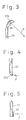
- Figure 3 shows another embodiment of the invention.
- a reflection mirror 37b is fitted to an upper part of the transparent light guide plate 23, and the reflection mirror 37b reflects the scanning beam P out through the emission window 25.
- the hologram 27 is not needed at the emission window 25.
- the reflection mirror 37b is fixed to the upper end (opposite to the commodity) of the transparent light guide plate 23 by adhesion or vapor deposition.
- Figure 4 shows still another embodiment of the invention.
- a lower end face 23a of the transparent light guide 23 is obliquely cut. Without the lower reflection mirror 37a of Fig. 2, the lower end face 23a directly entirely reflects a scanning beam upward into the transparent light guide plate 23.
- a hologram 38 may be arranged at a lower end portion of the transparent light guide 23.
- the hologram 38 diffracts the scanning beam P from the polygonal mirror 31 (Fig. 2) in a predetermined direction to guide the beam upward into the transparent light guide plate 23.
- FIG. 6 shows a laser beam scanning and signal light collecting optical system according to an embodiment of the present invention.
- a laser source 41 an He-Ne laser or a semiconductor laser
- emits a light beam which is converted by a beam shaping lens 43 into a beam having a predetermined diameter and shape.
- the beam enters the polygonal mirror 31, and due to the rotation of the polygonal mirror 31 around the shaft 33, the beam becomes the scanning beam P which enters the transparent light guide plate 23.
- the beam P traces the scanning beam path mentioned before.
- the beam scanning the bar code B (Fig. 34) of the commodity 8 is accordingly scattered, and part of the scattered light again enters, as signal light S, the transparent light guide plate 23.
- the signal light S traces the same path as before and returns to the polygonal mirror 31.
- the signal light S is then reflected by the polygonal mirror 31 and by a holed concave mirror 49, and guided to a photodetector 51.
- the processes carried out after the detection of the signal light by the photodetector 51 are not the object of the invention and are well known, and therefore, a detailed explanation thereof is omitted.
- the size and position of a pinhole 49a of the holed concave mirror 49 are set so as not to interfere with a beam traveling toward the polygonal mirror 31.
- the scanning optical system is incorporated in the substrate 20 but not disposed inside the transparent light guide plate 23, and thus the transparent light guide 23 may have a compact design.
- a customer can easily observe a reading operation of the bar code B from the back of and through the transparent light guide plate 23.
- the light source need not be incorporated inside the substrate 20 but can be located outside the substrate, and an outgoing beam from the outside light source guided into the substrate.
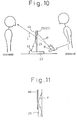
- Figures 9 to 11 show an embodiment which enables a customer to observe a bar code B of a commodity as well as a price display.
- the scanning optical system (such as the polygonal mirror 31 and mirror 37a) incorporated inside the substrate 20 provides a scanning beam, which is propagated inside the light guide plate 23 in parallel and externally emitted from the emission window 25 in a predetermined direction. Since the support portion is transparent, a customer can observe a bar code but cannot simultaneously observe a price display. This is because the price display is usually oriented toward an operator, and thus cannot be seen by the customer. According to the embodiment of Figs. 9 to 11, a display (an indicator) 53 is arranged on the substrate 20 and oriented toward the operator, but information displayed on the display can be seen by a customer positioned behind the display.
- FIGs 9, 10, and 11 show a basic arrangement of the stand type laser scanner according to the embodiment of the invention.
- a transparent light guide 23 is fitted on a substrate 20.
- a scanning beam emission window 25 composed of a hologram 27 is fitted to an upper part of the light guide plate.
- the substrate 20 incorporates a scanning optical system having a polygonal mirror 31 rotated by a motor 35 (Fig. 2). In response to the rotation, the polygonal mirror 31 guides a beam in a plane of the substrate 20. The beam is guided by a reflection mirror 37a (Fig. 2) upward into the transparent light guide plate 23.
- the scanning beam inside the transparent light guide plate 23 repeats a total reflection, and as shown in the figures, is diffracted by and emitted from the emission window (hologram) 25 in a predetermined direction to irradiate a bar code.
- a reflection type hologram 42 is formed at the back thereof, i.e., the customer's side opposite to the emission window 25.
- a price indicator (display) 53 is integrally obliquely arranged on the substrate 20 on the same side as the reflection type hologram 42, to face the reflection type hologram 42 of the transparent light guide plate 23.
- the reflection type hologram has diffraction characteristics of reflecting light having a specific wavelength, and the diffraction characteristics can be optionally controlled by properly designing a pitch of the hologram (interference fringes), etc.
- information light L (Fig. 10) from the price indicator 53 is reflected and diffracted by the reflection type hologram 42 in a predetermined direction, to be able to be seen by a customer.
- the customer can see a virtual image of a price (Yen 123 in the figure) on the indicator 53 as well as a bar code B on a commodity handled by the operator.
- This principle is the same as the principle of a headup display that overlays information light (corresponding to the price information) over a background (corresponding to the bar code of the commodity).
- the color of the information light L of the indicator 53 preferably matches the color, for example, green, of light (having the particular wavelength) reflected from the reflection type hologram 42.
- the scanning beam P propagated in the transparent light guide plate 23 also enters the reflection type hologram 42 for the indicator. If the wavelength of the scanning beam P is selected to be different (for example, red) from the selected wavelength of the reflection type hologram 42, it will not be affected by the reflection type hologram 42. Namely, as if the reflection type hologram 42 were omitted, the scanning beam is propagated upward by a repetitive total reflection in the transparent light guide plate 23.
- the hologram 42 may be formed at either side of the light guide plate.
- the price information light L from the indicator 53 is reflected and diffracted by the reflection type hologram 42 in a predetermined direction, so that a virtual image of the information substantially overlaps a bar code of a commodity positioned behind the transparent light guide plate 23. Namely, as in the headup display, a customer can observe the bar code as well as the price information light, one upon the other, without shifting position.
- Figures 12 to 17B show embodiments which read a bar code B by using a plurality of crossing scanning line patterns.
- scanning line patterns that cross and are oriented in at least two directions. If only one scanning line is used, the scanning line may not impinge on the bar code, depending on the orientation of the commodity (bar code) handled by an operator, and as a result, the bar code cannot be read. This frequently happens when the bar code is small. For a very small bar code, at least three to five multidirectional crossing patterns are needed.
- FIGs. 1 to 11 basically employ a single (unidirectional) scanning line.
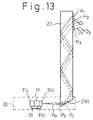
- Figures 12 and 13 show an embodiment of a stand type laser scanner employing multiple scanning lines.
- a transparent light guide plate 23 is integrally formed on a substrate 20 (Fig. 13), and a scanning beam emission window 25 is formed at an upper part of the light guide plate.
- the emission window 25 has a plurality of holograms H1, H2, and H3 arranged vertically on a substantially vertical plane.
- the substrate 20 incorporates a scanning optical system having a polygonal mirror 31 rotated by a motor 35. In response to the rotation, the polygonal mirror 31 guides a beam in a plane of the substrate 20. The beam is guided upward by a lower end face 23a of the transparent light guide plate 23 into the guide plate.
- the scanning beam in the transparent light guide plate 23 repeats a total reflection, and as shown in the figures, is diffracted by and emitted from the emission window 25 in predetermined directions.
- the emission directions can be set by properly designing the pitches of interference fringes of the holograms H1, H2, and H3.
- numeral 41 denotes a semiconductor laser serving as a light source.
- the scanning beam from the polygonal mirror 31 is propagated upward in the transparent light guide plate 23 due to the repetitive total reflection.
- the holograms H1, H2, and H3 receive the coherent scanning beam and emit beams in respective diffraction directions D1, D2, and D3 as shown in Fig. 13.
- the middle hologram H2 for example, does not turn (twist) the scanning direction by diffraction but provides a scanning beam b that is in parallel with the incident scanning beam P.
- the holograms H1 and H3 provide twisted scanning lines a and c due to the diffraction, Namely, the scanning lines a, b, and c form three scanning line patterns crossing one another.
- the unidirectional scan (parallel scan) in the transparent light guide plate 23 is converted by the holograms H1, H2, and H3 into the scanning patterns of three directions crossing one another.
- the scanning lines a and c are not twisted sufficiently and substantially in parallel with each other.
- a bar code reading operation with the stand type scanner is usually carried out, however, by putting a bar code (a commodity) on a table so that a region to be read is close to the surface of the table which is spaced from the holograms by a certain distance.
- the cross pattern scanning method of the invention therefore, raises no problems in practical use.
- the number of scanning lines can be increased infinitely in theory, by increasing the number of holograms, to thereby realize an all-round reading.
- angles of the reflection surfaces 31a, 31b, ..., 31i of the polygonal mirror 31 may be made slightly different from one another, to separate a scanning beam in parallel so that coherent incident scanning beams for the respective holograms are easily formed as shown in Fig. 13.
- Figures 14A and 14B schematically show the way of forming the hologram H2 that produces the untwisted scanning line b, and recreating the line b.
- a hologram dry plate 70 is irradiated with two spherical waves (reference light and object light) coming in the direction of an axis y (in a plane of the hologram dry plate). Interference exposure by the waves forms the hologram H2.
- a recreation beam Lr is emitted from a spot light source of the reference light, which is one of the holograms forming light, toward the hologram H2, the untwisted diffraction beam b is recreated (Fig. 14B).
- Figures 15A and 15B show optical systems for forming and recreating the twisted scanning lines a and c.
- the spot light source for the forming waves is simply shifted in a direction x in a forming process of a hologram.
- the recreation beam Lr is made incident on the hologram in the direction y similar to Fig. 14B the diffraction light is twisted to provide the twisted scanning line c (or a) as shown in Fig. 15B.
- wavelengths of the forming waves and recreation wave may be made different from one other to cause a chromatic aberration with which the twisted scanning lines are formed.
- a plurality of holograms are employed in a simple and compact structure to form multidirectional scanning line patterns which can improve the quality of a bar code reading operation.
- a scanning beam from the scanning optical system incorporated in the substrate is propagated in parallel with the light guide plate and externally emitted from the emission portion in predetermined directions.
- a plurality of the holograms arranged at the emission portion diffract respective scanning beams in directions determined by the respective holograms, thereby easily crossing the scanning lines with one another.
- the number of the scanning lines can be easily increased by increasing the number of the holograms arranged at the emission portion, thereby realizing, without an increase of the overall size, a laser scanner that reads bar codes without error.
- Figures 16 to 23 show embodiments having a further improved laser beam utilization factor.
- a beam is propagated inside the stand (transparent light guide plate), and only a part of the scanning beam entering the stand is effectively used for reading bar codes. Namely, the utilization efficiency of the scanning beam is not always satisfactory.
- the laser beam P emitted from the laser source 41 is guided by the polygonal mirror 31 from A1 to B1, from A2 to B2, and from A3 to B3 (refer to Fig. 23(D)) to provide beams, which enter the lower part of the transparent stand portion 23, are propagated inside the transparent stand portion by repetitive total reflection, and made incident on the upper hologram windows H1, H2, and H3, respectively.
- Respective surfaces 31a, 31b, and 31c of the polygonal mirror 31 have different inclinations, so that the beam reflected by the respective surfaces provides beams indicated with reference marks Pa, Pb, and Pc in Fig. 13.
- the scanning beam Pa travels toward the hologram window H1, exits therefrom, and travels obliquely as indicated with a reference mark D1 (the scanning line a).
- the scanning beam Pc travels toward the hologram window H3, exits therefrom, and travels obliquely opposite to the direction D1 as indicated with a reference mark D3 (the scanning line c).
- the scanning beam Pb travels toward the hologram window H2, exits therefrom, and travels horizontally as indicated with a reference mark D2 (the scanning line b).
- the scanning line b is in parallel with the plane of the transparent light guide plate 23.
- the scanning width of a beam widens while the beam is propagated upward inside the transparent light guide plate 23.
- each of the vertical, horizontal, and oblique scanning patterns requires a one time scanning, so that, as apparent in Fig. 23, three scanning operations of Al to B1, A2 to B2, and A3 to B3 are needed. This means that the polygonal mirror 31 needs three surfaces, which lowers the performance of the scanner.
- a laser beam scanning line dividing means is arranged inside the transparent light guide plate 23. This dividing means deflects the laser beam portions usually not used toward the respective hologram emission windows, thereby improving the utilization efficiency of laser beam.
- the laser beam scanning line dividing means can form a set of vertical, horizontal, and oblique bar code reading patterns in a short time.
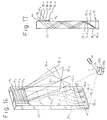
- Figure 16 shows an embodiment of a stand type scanner for a bar code reader, having the scanning line dividing means.
- a numeral 31 denotes a polygonal mirror, and 41 a laser source for repeatedly providing a laser beam P from (1) to (5).
- the polygonal mirror 31 has surfaces 31a, 31b, 31c, ... having an identical inclination to guide the laser beam P on the same locus from (1) to (5).
- Numeral 23 denotes a transparent light guide plate made of a transparent glass plate arranged upright. A lower part of the light guide plate agrees with the locus of the laser beam P.
- An upper part of the light guide plate 23 has four rows of emission hologram windows H1 to H4.
- Numerals 16-1 to 16-4 denote reflection type holograms arranged at the lower part of the light guide plate 23 along the locus of the laser beam to form the laser beam dividing means.
- the holograms 16-1 to 16-4 have different optical characteristics respectively.
- the hologram 16-1 deflects the laser beam P toward the hologram window H1 as indicated with a reference mark 17-1 (Fig. 18 (A)).
- the hologram 16-2 deflects the laser beam P toward the hologram window H2 as indicated with a reference mark 17-2 (Fig. 18 (B)).
- the hologram 16-3 deflects the laser beam P toward the hologram window H3 as indicated with a reference mark 17-3 (Fig. 18 (C)).
- the hologram 16-4 deflects the laser beam P toward the hologram window H4 as indicated with a reference mark 17-4 (Fig. 18 (D)).
- the hologram windows H1 to H4 have optical characteristics to vertically, horizontally, and obliquely diffract the laser beams 17-1 to 17-4 as indicated with reference marks 18-1 to 18-4 in Fig. 16.
- the hologram 16-1 diffracts the beam in the section from (1) to (2) to provide the laser beam 17-1, which repeats a total reflection in the light guide plate 23 and reaches the hologram window H1, which diffracts the laser beam to provide the scanning laser beam 18-1.
- the hologram 16-2 diffracts the beam to provide the laser beam 17-2, which is diffracted by the hologram window H2 to form the scanning beam 18-2.
- the hologram 16-3 diffracts the beam to provide the laser beam 17-3, which is diffracted by the hologram window H3 to form the scanning beam 18-3.
- the hologram 16-4 diffracts the beam to provide the laser beam 17-4, which is diffracted by the hologram window H4 to form the scanning beam 18-4.
- the beam is divided into the four laser beams 17-1 to 17-4, which become the laser beams 18-1 to 18-4 emitted from the respective hologram windows and used to read a bar code, thereby further improving the utilization efficiency of the laser beam P.
- a set of the vertical, horizontal, and oblique patterns 18-1 to 18-4 is formed by one scan of the laser beam P from (1) to (5) by a single surface of the polygonal mirror 31. This can shorten a time for forming the set of the patterns, to thereby improve the performance of the scanner.
- Figures 20 and 21 show another embodiment different from the one shown in Figs. 16 and 17
- parts corresponding to those of Figs. 16 and 17 are represented with like reference marks.
- a transparent light guide plate 23 has, on its lower surface, four divided reflection surfaces 21-1 to 21-4 having different inclinations.
- the reflection surfaces 21-1 to 21-4 reflect the laser beam, and the reflected beams are propagated, similar to the laser beams 17-1 to 17-4, inside the light guide plate 23 toward emission hologram windows Hl to H4.
- FIG. 22 shows still another embodiment.
- a transparent light guide plate 23 has, at its intermediate portion, four transmission type holograms 61-1 to 61-4 having different diffraction characteristics and arranged side by side in a scanning direction.
- a laser beam propagated from a lower part inside the light guide plate 23 sequentially scans the holograms 61-1 to 61-4, which diffract the laser beam in predetermined directions, thereby dividing the laser beam into four beams.
- the divided four laser beams are emitted from respective emission hologram windows H1 to H4.
- a single scanning laser beam provided by a laser beam scanning means is divided into a plurality of scanning laser beams, which are directed toward emission hologram windows for emitting the divided laser beams in different directions.
- This arrangement can improve the utilization efficiency of laser beam scanning lines when reading bar codes.
- the embodiments can form a set of vertical, horizontal, and oblique scanning patterns for reading bar codes in a short time, to thereby improve the performance of the bar code reader.
- Figures 24 to 29 show embodiments each having a common substrate incorporating a laser scanning portion, for emitting various scanning patterns from a light emission window 25 depending on the use.
- a bar code B on a commodity is easily read with orthogonal two scanning patterns.
- the two scanning patterns can perform a reading operation in any direction. If there is only one scanning line, the scanning line may not completely cross the bar code depending on the orientation of the commodity (bar code) handled by an operator, and the bar code may not be read. This problem becomes bigger as the bar code becomes smaller. For example, reading a short (truncate) symbol may require at least three to five multidirectionally crossing scanning patterns.
- Bar codes used in a physical distribution such as those based on Code 39, Interleaved 2 out of 5 have low information density and no limitation in the number of digits, and thus are extremely long laterally.
- the orthogonal patterns or the equiangular crossing patterns oriented in three to five directions are incapable of carrying out the multidirectional reading operation, and it is necessary to adjust an angle of the bar code when reading the same.
- a diffracted direction of an outgoing beam from a light emission window is uniquely determined by a hologram, so that the diffracted direction cannot be changed without changing (preparing again) the design of the hologram.
- Figures 24 and 25 show a basic arrangement of an embodiment of a laser scanner having an exchangeable transparent light guide plate 23.
- the transparent light guide plate 23 is removably fitted on a substrate 20.
- a hologram 27 for forming a scanning beam emission window 25 is arranged at an upper part of the transparent light guide plate 23.
- the hollow substrate 20 incorporates a scanning optical system having a polygonal mirror 31 rotated by a motor 35. According to the rotation, the polygonal mirror 31 guides a beam in a plane of the substrate 20.
- a scanning beam introducing hologram 38 formed at a lower end of the transparent light guide plate 23 diffracts the beam upward into the transparent light guide plate 23.
- the scanning beam inside the transparent light guide plate 23 repeats a total reflection, and as shown in the figures, is diffracted by and emitted from the emission window 25 (hologram 27) in a predetermined direction.
- An incident direction toward the transparent light guide plate 23 and an outgoing direction from the transparent light guide plate 23 are optionally set by properly designing pitches of interference fringes of the holograms 27 and 38.
- the substrate 20 has recesses 64 for removably receiving the transparent light guide plate 23.
- the recesses 64 are fixedly provided with guides 68 (Fig. 25) for easily fitting and removing the transparent light guide plate 23 in a sliding manner in a vertical direction.
- the guides 68 may be a pair of facing channel-shaped groove members as shown in the figure.
- a sealing window glass 66 for preventing water, dust etc., from entering the inside of the substrate 20 is arranged at a part of the substrate 20 facing the introducing hologram 38 of the transparent light guide plate 23.
- Figures 26 to 29 show several examples of the transparent light guide plate 23, having various holograms (emission portions) 27.
- Each of the examples has three holograms 27 (H1, H2, and H3) at an emission portion thereof to produce three scanning patterns.
- a scanning beam P from the polygonal mirror 31 is propagated upward and in parallel inside the transparent light guide plate 23 due to repetitive total reflection.
- the respective holograms H1, H2, and H3 receive the coherent scanning lines, and provide beams in respective diffraction directions (corresponding to scanning lines a, b, and c) as shown in Fig. 26.
- the middle hologram H2 for example, does not twist the scanning direction of the beam by diffraction and provides the scanning beam b that is in parallel with the incident scanning beam.
- the holograms H1 and H2 twist the incident beams by diffraction and provide the scanning lines a and c.
- the scanning lines a, b, and c form three scanning patterns crossing one another.
- the unidirectional scanning beam (coherent scanning beam) inside the transparent light guide plate 23 is converted by the holograms H1, H2, and H3 into the scanning patterns of three directions crossing one another.
- the number of the scanning lines may be infinitely increased in theory, by increasing the number of the holograms.
- the scanning beam P is coherently separated by slightly changing the reflection surfaces of the polygonal mirror 31, thereby easily forming the coherent incident scanning beams for the holograms H1, H2, and H3 respectively.
- This embodiment is suitable for reading UPC system bar codes.
- Figure 27 shows another embodiment.
- a transparent light guide plate 23A has holograms H1', H2', and H3' which produce scanning patterns a', b', and c' having smaller crossing angles than those shown in Fig. 28.
- This embodiment is suitable for, for example, a bar code having an extremely long lateral length (with short height) which cannot be read by the scanning patterns of Fig. 26.
- the patterns having the small crossing angles can extend margins for adjusting the angle of a bar code.
- Figure 28 shows a transparent light guide plate 23B having an emission portion 25 provided with a single hologram 27. in this case, a diffraction direction shifts in parallel depending on an incident position on the hologram 27, thereby forming separated parallel patterns.
- the embodiment of Fig. 28 can also extend a positioning margin when reading extremely wide codes such as those based on Code 39 or Interleaved 2 out of 5.
- the transparent light guide plates 23 (Fig. 26), 23A (Fig. 27), and 23B (Fig. 28) can be exchanged one for the other, depending on the conditions of the commodities and sales points, to provide required scanning patterns.
- Figure 29 shows an embodiment that can cope with the size of a commodity.
- This embodiment employs a transparent light guide plate 23C having holograms Ha, Hb, and Hc which have different focal lengths f1, f2, and f3, respectively, thereby substantially expanding the reading regions (depths).
- the transparent light guide plate 23 has the emission portion 25 formed of holograms.
- the light guide plate 23 (23A, 23B, 23C) having a light emission window of a specific purpose is removably fitted to the common substrate 20 to easily provide various scanning patterns without changing the scanning optical system.
- Embodiments of the present invention are applicable in POS systems employed in registers in supermarkets, department stores, and other speciality stores.
Landscapes
- Physics & Mathematics (AREA)
- Engineering & Computer Science (AREA)
- Electromagnetism (AREA)
- Artificial Intelligence (AREA)
- Toxicology (AREA)
- General Health & Medical Sciences (AREA)
- Health & Medical Sciences (AREA)
- Computer Vision & Pattern Recognition (AREA)
- General Physics & Mathematics (AREA)
- Theoretical Computer Science (AREA)
- Mechanical Optical Scanning Systems (AREA)
- Holo Graphy (AREA)
- Character Input (AREA)
Claims (33)
- Strichkodelesevorrichtung zum Lesen eines Strichkodes auf einem Objekt, mit:einer Laserquelle (41) zum Emittieren eines Laserstrahls;einem Laserstrahlscanmittel (31; 30) zum Ableiten, von dem emittierten Laserstrahl, eines Scanstrahls (P), der aus der Vorrichtung durch ein Lichtemissionsfenster (25) hin zu dem Objekt hinaustritt und in einem vorbestimmten Scanmuster über den Strichkode auf dem Objekt scannt; undeinem optischen Detektionsmittel (49, 51) zum Detektieren von Licht, das von dem Strichkode hin zu der Vorrichtung zurück reflektiert wird;welches Laserstrahlscanmittel und welches optische Detektionsmittel beide in einer Basiseinheit (20) der Vorrichtung inkorporiert sind, und welches Lichtemissionsfenster auf der Basiseinheit durch ein Stützglied (23) gestützt ist;
dadurch gekennzeichnet, daß das genannte Stützglied (23) transparent ist und als Lichtleiter dient, durch den der genannte Scanstrahl und das reflektierte Licht ausgebreitet werden. - Vorrichtung nach Anspruch 1, bei der die genannte Laserquelle (41) auch in der genannten Basiseinheit (20) angeordnet ist.
- Vorrichtung nach Anspruch 1 oder 2, bei der das genannte Stützglied (23) plattenartig ist.
- Vorrichtung nach irgendeinem vorhergehenden Anspruch, bei der das genannte Lichtemissionsfenster (25) an einem oberen Ende des genannten Stützgliedes (23) gebildet ist.
- Vorrichtung nach irgendeinem vorhergehenden Anspruch, bei der das genannte Lichtemissionsfenster (25) ein Hologramm (27) hat, das auf ihm vorgesehen ist, zum Beugen des genannten Scanstrahls (P), so daß er in einer vorbestimmten Richtung aus der Vorrichtung hinaustritt.
- Vorrichtung nach Anspruch 5, bei der das genannte Lichtemissionsfenster (25) eine Vielzahl von Hologrammen (H₁, H₂, H₃) hat, die den genannten Scanstrahl in verschiedenen jeweiligen vorbestimmten Richtungen (D₁, D₂, D₃) hin zu dem Strichkode beugen.
- Vorrichtung nach Anspruch 6, bei der die Hologramme (H₁, H₂, H₃) von der genannten Vielzahl verschiedene Beugungseigenschaften haben und dazu dienen, eine Vielzahl von Scanstrahlen zu erzeugen, die sich kreuzende Scanlinien (a, b, c) auf dem Objekt verfolgen.
- Vorrichtung nach Anspruch 6 oder 7, bei der die genannten Hologramme verschiedene Brennweiten haben.
- Vorrichtung nach Anspruch 6, 7 oder 8, bei der die Scanlinie (b), die auf dem Objekt durch den Scanstrahl verfolgt wird, der durch wenigstens eines der Hologramme (H₂) gebeugt ist, zu der Richtung, in der der Laserstrahl über das betreffende Hologramm scannt, im wesentlichen parallel ist, und die Scanlinien (a, c), die auf dem Objekt durch die Scanstrahlen verfolgt werden, die durch andere Hologramme (H₁, H₃) gebeugt sind, zu der Richtung, in der der Laserstrahl über das betreffende Hologramm scannt, jeweils nicht parallel sind.
- Vorrichtung nach Anspruch 9, bei der das genannte Laserstrahlscanmittel einen rotierbaren Polygonspiegel (31) umfaßt, der unterschiedlich geneigte Reflexionsoberflächen (31a, 31b, 31c) hat, zum Reflektieren und Teilen des Laserstrahls, der durch die genannte Laserquelle emittiert wurde, in eine Vielzahl von Scanstrahlen, die jeweilig hin zu den zugeordneten Hologrammen gerichtet sind.
- Vorrichtung nach Anspruch 9, ferner mit einem Laserstrahlteilungsmittel (16-1, ..., 16-4), zum Teilen des Scanstrahls, der durch das Laserstrahlscanmittel (31) erzeugt wurde, in eine Vielzahl von Scanstrahlen (17-1, ..., 17-4), um jeweilig auf den zugeordneten Hologrammen (H₁, H₄) des genannten Lichtemissionsfensters zum Einfallen gebracht zu werden.
- Vorrichtung nach Anspruch 11, bei der das genannte Laserstrahlteilungsmittel eine Vielzahl von Teilungshologrammen umfaßt, die an dem genannten Stützglied vorgesehen sind.
- Vorrichtung nach Anspruch 12, bei der die genannten Teilungshologramme Hologramme des Reflexionstyps sind.
- Vorrichtung nach Anspruch 12 oder 13, bei der die genannten Teilungshologramme (16-1, ..., 16-4) längs einer Linie ausgerichtet sind und das genannte Laserstrahlscanmittel (31) so ist, daß der Scanstrahl, der durch dieses erzeugt wird, längs jener Linie scannt, wenn die Vorrichtung in Gebrauch ist.
- Vorrichtung nach Anspruch 14, bei der die genannten Hologramme des Reflexionstyps (16-1, ..., 16-4) verschiedene Brechungscharakteristiken haben, so daß die Scanstrahlen, die jeweilig durch jene Hologramme erzeugt werden, in die transparente Stütze (23) in verschiedenen jeweiligen Richtungen hin zu jeweiligen Hologrammen (H₁, ..., H₄) gebeugt werden, die an dem Lichtemissionsfenster vorgesehen sind.
- Vorrichtung nach Anspruch 11, bei der das genannte Laserstrahlteilungsmittel eine Vielzahl von geneigten Reflexionsoberflächen (21-1, ..., 21-4) umfaßt, die an dem unteren Ende des genannten Stützmittels (23) vorgesehen sind und verschiedene jeweilige Neigungsrichtungen haben.
- Vorrichtung nach Anspruch 11, bei der das genannte Laserstrahlteilungsmittel eine Vielzahl von Hologrammen (61-1, ..., 61-4) des Durchlaßtyps hat, die in dem genannten Stützglied (23) vorgesehen sind und verschiedene jeweilige Beugungscharakteristiken haben, so daß die Scanstrahlen, die jeweilig durch jene Hologramme erzeugt werden, in verschiedenen Richtungen hin zu jeweiligen Hologrammen (15-1, ..., 15-4) gebeugt werden, die an dem genannten Lichtemissionsfenster vorgesehen sind.
- Vorrichtung nach irgendeinem der Ansprüche 1 bis 4, ferner mit einem oberen Reflexionsspiegel (37b), der an dem oberen Ende des genannten Stützgliedes vorgesehen ist, um den Scanstrahl, der durch die transparente Stütze (23) durchgelassen wurde, in einer vorbestimmten Richtung zu reflektieren, so daß der Scanstrahl nach solch einer Reflexion durch das genannte Lichtemissionsfenster (25) hin zu dem Strichkode hindurchtritt.
- Vorrichtung nach irgendeinem vorhergehenden Anspruch, ferner mit einem unteren Reflexionsmittel (37a; 23a; 38) zum Reflektieren des Laserstrahls in das genannte Stützglied (23).
- Vorrichtung nach Anspruch 19, bei der das genannte untere Reflexionsmittel einen unteren Reflexionsspiegel (37a) umfaßt, der in der genannten Basiseinheit (20) vorgesehen ist.
- Vorrichtung nach Anspruch 19, bei der das genannte Stützglied (23) eine schräge Oberfläche (23a) an seinem unteren Ende hat, welche Oberfläche als das genannte untere Reflexionsmittel dient.
- Vorrichtung nach Anspruch 19, bei der das genannte untere Reflexionsmittel ein Hologramm (38) umfaßt, das an dem unteren Ende des genannten Stützgliedes (23) vorgesehen ist, um den Laserstrahl in das genannte Stützglied zu beugen.
- Vorrichtung nach irgendeinem vorhergehenden Anspruch, bei der das genannte Laserstrahlscanmittel einen rotierbaren Polygonspiegel (31) umfaßt, der Reflexionsoberflächen (31a, 31b, 31c) hat, zum Reflektieren des genannten Laserstrahls in das Stützglied (23).
- Vorrichtung nach irgendeinem vorhergehenden Anspruch, ferner mit einem konkaven Spiegel (49), der zum Empfangen des Lichtes angeordnet ist, das von dem Strichkode zurück reflektiert wird, und zum Reflektieren jenes Lichtes hin zu dem genannten optischen Detektionsmittel (51).
- Vorrichtung nach Anspruch 24, bei der der genannte konkave Spiegel ein Nadelloch (49a) hat, durch welches der Laserstrahl, der durch die genannte Laserquelle emittiert wird, hindurchtritt.
- Vorrichtung nach irgendeinem der Ansprüche 1 bis 22, bei der das genannte Laserstrahlscanmittel einen Galvanospiegel (30) umfaßt.
- Vorrichtung nach irgendeinem vorhergehenden Anspruch, ferner mit einem Hologramm (42) des Reflexionstyps, das an dem genannten Stützglied (23) vorgesehen ist, um nur eine spezifische Wellenlänge von Licht in einer vorbestimmten Richtung zu reflektieren, und einem Indikator (53), der auf der Seite des Stützgliedes angeordnet ist, die der Seite gegenüberliegt, auf der das genannte Lichtemissionsfenster (25) angeordnet ist, zum Anzeigen von Informationen;
welcher Indikator Licht erzeugt, das eine Wellenlänge hat, die mit der genannten spezifischen Wellenlänge im wesentlichen identisch ist, so daß solches Licht von dem Indikator durch das genannte Hologramm (42) des Reflexionstyps reflektiert wird und es einem Betrachter, der auf derselben Seite des genannten Stützgliedes wie der Indikator positioniert ist, von einer Position dicht an dem Strichkode zu kommen scheint. - Vorrichtung nach Anspruch 27, bei der das genannte Hologramm (42) des Reflexionstyps auf jener Seitenfläche des genannten Stützgliedes (23) vorgesehen ist, die sich dichter an dem genannten Indikator befindet.
- Vorrichtung nach Anspruch 27 oder 28, bei der sich die Wellenlänge des genannten Scanstrahls von der Wellenlänge des Lichtes unterscheidet, das durch den genannten Indikator (53) erzeugt wird.
- Vorrichtung nach irgendeinem vorhergehenden Anspruch, ferner mit einem Stützmontagemittel (66, 68) zum lösbaren Montieren des Stützgliedes (23) an der genannten Basiseinheit (20).
- Vorrichtung nach Anspruch 30, bei der die genannte Basiseinheit (20) eine Vertiefung (64) hat, in der das genannte Stützmontagemittel (66, 68) vorgesehen ist.
- Vorrichtung nach Anspruch 31, zusammen mit Anspruch 3 oder irgendeinem Anspruch, der von Anspruch 3 abhängt, bei der das genannte Stützmontagemittel Führungsschienen (68) umfaßt, die an der genannten Basiseinheit (20) in ihrer genannten Vertiefung (64) vorgesehen sind, so daß das plattenartige Stützglied (23) in den Führungsschienen (68) gleitend angebracht werden kann.
- Vorrichtung nach irgendeinem vorhergehenden Anspruch, bei der die genannte Laserquelle (41) eine Laserdiode ist.
Applications Claiming Priority (11)
| Application Number | Priority Date | Filing Date | Title |
|---|---|---|---|
| JP240124/89 | 1989-09-18 | ||
| JP240137/89 | 1989-09-18 | ||
| JP24013089 | 1989-09-18 | ||
| JP24012489 | 1989-09-18 | ||
| JP240123/89 | 1989-09-18 | ||
| JP24013789 | 1989-09-18 | ||
| JP240130/89 | 1989-09-18 | ||
| JP24012389 | 1989-09-18 | ||
| JP244361/89 | 1989-09-20 | ||
| JP24436189 | 1989-09-20 | ||
| PCT/JP1990/001181 WO1991004550A1 (fr) | 1989-09-18 | 1990-09-14 | Analyseur laser pour lecteur de code a barres |
Publications (3)
| Publication Number | Publication Date |
|---|---|
| EP0446364A1 EP0446364A1 (de) | 1991-09-18 |
| EP0446364A4 EP0446364A4 (en) | 1992-06-10 |
| EP0446364B1 true EP0446364B1 (de) | 1996-04-24 |
Family
ID=27530032
Family Applications (1)
| Application Number | Title | Priority Date | Filing Date |
|---|---|---|---|
| EP90913548A Expired - Lifetime EP0446364B1 (de) | 1989-09-18 | 1990-09-14 | Laserabtaster für strichkodeleser |
Country Status (5)
| Country | Link |
|---|---|
| US (1) | US5266788A (de) |
| EP (1) | EP0446364B1 (de) |
| KR (1) | KR940010808B1 (de) |
| DE (1) | DE69026705T2 (de) |
| WO (1) | WO1991004550A1 (de) |
Families Citing this family (32)
| Publication number | Priority date | Publication date | Assignee | Title |
|---|---|---|---|---|
| CA2021519C (en) * | 1990-05-29 | 2001-09-04 | Jerome Swartz | Scanning system implemented on semiconductor or electro-optical substrate |
| US5491328A (en) * | 1991-09-24 | 1996-02-13 | Spectra-Physics Scanning Systems, Inc. | Checkout counter scanner having multiple scanning surfaces |
| US5229588A (en) | 1991-09-30 | 1993-07-20 | Ncr Corporation | Dual aperture optical scanner |
| US5475207A (en) * | 1992-07-14 | 1995-12-12 | Spectra-Physics Scanning Systems, Inc. | Multiple plane scanning system for data reading applications |
| BR9307581A (pt) * | 1992-12-04 | 1999-08-31 | Psc Inc | Acessório de varredura para um terminal portátil para coletar e entrar com dados, motor de varredura e receptor eletro-ótico |
| US5498862A (en) * | 1993-05-06 | 1996-03-12 | International Computers Limited | Side scanning bar code reader with vertical and horizontal scan patterns |
| JP2813283B2 (ja) * | 1993-07-14 | 1998-10-22 | 富士通株式会社 | バーコード読取り装置 |
| US6648227B2 (en) * | 2000-10-20 | 2003-11-18 | Symbol Technologies, Inc. | Scanning module for a bar code reader with a focusing lens |
| US6169614B1 (en) | 1999-05-21 | 2001-01-02 | Psc Scanning, Inc. | Wedged-shape holographic collector |
| RU2237282C2 (ru) * | 1999-08-30 | 2004-09-27 | Научно-технический кооператив "Вектор" | Устройство для считывания графической и текстовой информации |
| USD435556S (en) * | 1999-10-14 | 2000-12-26 | Hewlett-Packard Company | Guide lights for a hand-held scanner |
| US7100832B2 (en) | 2000-04-18 | 2006-09-05 | Metrologic Instruments, Inc. | Bioptical laser scanning system providing 360° of omnidirectional bar code symbol scanning coverage at point of sale station |
| US20030132291A1 (en) | 2002-01-11 | 2003-07-17 | Metrologic Instruments, Inc. | Point of sale (POS) station having bar code reading system with integrated internet-enabled customer-kiosk terminal |
| US7296748B2 (en) | 2002-01-11 | 2007-11-20 | Metrologic Instruments, Inc. | Bioptical laser scanning system providing 360° of omnidirectional bar code symbol scanning coverage at point of sale station |
| US6843416B2 (en) * | 2002-01-29 | 2005-01-18 | Symbol Technologies, Inc. | Integrated scanner on a common substrate |
| JP4003483B2 (ja) * | 2002-02-28 | 2007-11-07 | 株式会社デンソーウェーブ | 情報コード読取装置 |
| JP2005227220A (ja) * | 2004-02-16 | 2005-08-25 | Denso Corp | 距離検出装置 |
| DE102004053293A1 (de) * | 2004-11-04 | 2006-05-11 | Giesecke & Devrient Gmbh | Abtastvorrichtung für Barcodes |
| WO2007062098A2 (en) | 2005-11-21 | 2007-05-31 | Microvision, Inc. | Display with image-guiding substrate |
| US7589901B2 (en) * | 2007-07-10 | 2009-09-15 | Microvision, Inc. | Substrate-guided relays for use with scanned beam light sources |
| US7810976B2 (en) * | 2007-07-19 | 2010-10-12 | Panasonic Corporation | Surface emitting apparatus and image display apparatus using the surface emitting apparatus |
| JP4441574B2 (ja) | 2008-02-04 | 2010-03-31 | 東芝テック株式会社 | 店舗用精算装置 |
| US8531773B2 (en) | 2011-01-10 | 2013-09-10 | Microvision, Inc. | Substrate guided relay having a homogenizing layer |
| US8391668B2 (en) | 2011-01-13 | 2013-03-05 | Microvision, Inc. | Substrate guided relay having an absorbing edge to reduce alignment constraints |
| US8523076B2 (en) | 2012-01-10 | 2013-09-03 | Metrologic Instruments, Inc. | Omnidirectional laser scanning bar code symbol reader generating a laser scanning pattern with a highly non-uniform scan density with respect to line orientation |
| US9004359B2 (en) | 2012-05-16 | 2015-04-14 | Datalogic ADC, Inc. | Optical scanner with top down reader |
| USD708183S1 (en) * | 2012-06-08 | 2014-07-01 | Datalogic ADC, Inc. | Data reader for checkout station |
| EP3270580B1 (de) | 2016-07-15 | 2021-09-01 | Hand Held Products, Inc. | Bildgebungsscanner mit positionierung und anzeige |
| CN107622217B (zh) | 2016-07-15 | 2022-06-07 | 手持产品公司 | 具有定位和显示的成像扫描仪 |
| CN107622218A (zh) * | 2016-07-15 | 2018-01-23 | 手持产品公司 | 具有查看框架的条形码读取器 |
| US10007824B1 (en) | 2016-12-23 | 2018-06-26 | Datalogic Usa, Inc. | Target options for a data capture device with intuitive aiming involving specular objects |
| DE102017125182A1 (de) * | 2017-10-27 | 2019-05-02 | Valeo Schalter Und Sensoren Gmbh | Lichtaustrittsvorrichtung für einen Laserscanner |
Citations (1)
| Publication number | Priority date | Publication date | Assignee | Title |
|---|---|---|---|---|
| EP0194115A2 (de) * | 1985-02-28 | 1986-09-10 | Symbol Technologies, Inc. | Tragbarer Abtastkopf mit Laserdiode |
Family Cites Families (19)
| Publication number | Priority date | Publication date | Assignee | Title |
|---|---|---|---|---|
| US3643068A (en) * | 1969-03-12 | 1972-02-15 | Spartanics | Random oriented decoder for label decoding |
| US4009369A (en) * | 1974-05-03 | 1977-02-22 | Schiller Industries, Inc. | Polyphase scanner for bar code symbols |
| US4092061A (en) * | 1976-12-29 | 1978-05-30 | International Business Machines Corp. | Side-coupling of light for an optical fiber |
| US4093865A (en) * | 1977-04-29 | 1978-06-06 | National Semiconductor Corporation | Code symbol scanner using a double X bar pattern |
| US4297653A (en) * | 1979-04-30 | 1981-10-27 | Xerox Corporation | Hybrid semiconductor laser/detectors |
| US4369361A (en) * | 1980-03-25 | 1983-01-18 | Symbol Technologies, Inc. | Portable, stand-alone, desk-top laser scanning workstation for intelligent data acquisition terminal and method of scanning |
| US4398792A (en) * | 1981-02-03 | 1983-08-16 | The United States Of America As Represented By The Secretary Of The Air Force | Holographic coupler for fiber optic systems |
| US4591236A (en) * | 1984-02-13 | 1986-05-27 | International Business Machines Corporation | Optical scanner with beam directing holograms at window |
| JPS62243081A (ja) * | 1986-04-16 | 1987-10-23 | Minolta Camera Co Ltd | バ−コ−ドリ−ダ− |
| US4794237A (en) * | 1986-11-10 | 1988-12-27 | Ncr Corporation | Multidirectional holographic scanner |
| JPH0195377A (ja) * | 1987-10-07 | 1989-04-13 | Fujitsu Ltd | バーコード読取装置 |
| JPH07101433B2 (ja) * | 1988-04-28 | 1995-11-01 | 松下電器産業株式会社 | 光学的パターン検出装置 |
| KR930000691B1 (ko) * | 1988-09-20 | 1993-01-29 | 도오꾜오 덴끼 가부시끼가이샤 | 상품데이타 판독장치 |
| US5042821A (en) * | 1989-02-02 | 1991-08-27 | Spectra-Physics, Inc. | Seal for optical scanner window |
| JP2586954B2 (ja) * | 1989-11-24 | 1997-03-05 | ファナック株式会社 | 射出成形機における成形不良対策方法 |
| JPH03167684A (ja) * | 1989-11-28 | 1991-07-19 | Tokyo Electric Co Ltd | 商品データ読取装置 |
| US5105070A (en) * | 1990-12-10 | 1992-04-14 | Ncr Corporation | Bar code scanning apparatus with rotating housing member |
| US5115122A (en) * | 1990-12-12 | 1992-05-19 | Ncr Corporation | Compact optical scanning system |
| JPH06224046A (ja) * | 1993-01-26 | 1994-08-12 | Matsushita Electric Works Ltd | トランス |
-
1990
- 1990-09-14 EP EP90913548A patent/EP0446364B1/de not_active Expired - Lifetime
- 1990-09-14 US US07/700,170 patent/US5266788A/en not_active Expired - Lifetime
- 1990-09-14 DE DE69026705T patent/DE69026705T2/de not_active Expired - Fee Related
- 1990-09-14 KR KR1019910700497A patent/KR940010808B1/ko not_active Expired - Fee Related
- 1990-09-14 WO PCT/JP1990/001181 patent/WO1991004550A1/ja not_active Ceased
Patent Citations (1)
| Publication number | Priority date | Publication date | Assignee | Title |
|---|---|---|---|---|
| EP0194115A2 (de) * | 1985-02-28 | 1986-09-10 | Symbol Technologies, Inc. | Tragbarer Abtastkopf mit Laserdiode |
Also Published As
| Publication number | Publication date |
|---|---|
| US5266788A (en) | 1993-11-30 |
| KR940010808B1 (ko) | 1994-11-16 |
| DE69026705T2 (de) | 1996-10-31 |
| DE69026705D1 (de) | 1996-05-30 |
| WO1991004550A1 (fr) | 1991-04-04 |
| KR920701923A (ko) | 1992-08-12 |
| EP0446364A4 (en) | 1992-06-10 |
| EP0446364A1 (de) | 1991-09-18 |
Similar Documents
| Publication | Publication Date | Title |
|---|---|---|
| EP0446364B1 (de) | Laserabtaster für strichkodeleser | |
| EP0295936B1 (de) | Anordnung zur Erzeugung eines optischen Abtastrasters für Laserabtaster | |
| US6991167B2 (en) | Bioptical laser scanning system providing 360° of omnidirectional bar code symbol scanning coverage at a point of sale (POS) station | |
| US7407103B2 (en) | Bioptical holographic laser scanning system | |
| US5073702A (en) | Multiple beam bar code scanner | |
| US6523750B1 (en) | Laser scanning system employing light collection surfaces having optical axes disposed off the bragg angle of the holographic optical elements of the holographic scanning disc thereof | |
| US7395968B2 (en) | Laser scanning based bar code symbol reading system for producing a 3-D scanning volume substantially free of spatially and temporally coincident laser scanning planes | |
| KR900008270B1 (ko) | 레이저 광선 주사장치 | |
| JPH0628508A (ja) | 光学読取方法および光学読取装置 | |
| KR20000067798A (ko) | 광주사 장치 | |
| EP0396485B1 (de) | Strichkodeleser mit grosser Schärfentiefe | |
| EP0151915A2 (de) | Optischer Abtaster mit Strahlrichthologrammen am Abtastfenster | |
| CN101025787A (zh) | 光扫描设备 | |
| EP0478376A2 (de) | Optischer Abtaster | |
| US6199759B1 (en) | Bar code symbol scanning system having a holographic laser scanning disc utilizing maximum light collection surface area thereof and having scanning facets with optimized light collection efficiency | |
| JP2757883B2 (ja) | バーコードリーダ用レーザスキャナ | |
| JPWO1991004550A1 (ja) | バーコードリーダ用レーザスキャナ | |
| JP2972411B2 (ja) | 光学的読取装置 | |
| JP2576604B2 (ja) | レーザ光走査装置 | |
| JP2746977B2 (ja) | 走査パターン形成装置 | |
| JP2676994B2 (ja) | 光学走査装置 | |
| JP2760163B2 (ja) | 読取装置 | |
| JPH03129582A (ja) | バーコード読取り装置 | |
| JPH0685189B2 (ja) | 情報読取装置 |
Legal Events
| Date | Code | Title | Description |
|---|---|---|---|
| PUAI | Public reference made under article 153(3) epc to a published international application that has entered the european phase |
Free format text: ORIGINAL CODE: 0009012 |
|
| 17P | Request for examination filed |
Effective date: 19910523 |
|
| AK | Designated contracting states |
Kind code of ref document: A1 Designated state(s): DE FR GB NL |
|
| A4 | Supplementary search report drawn up and despatched |
Effective date: 19920421 |
|
| AK | Designated contracting states |
Kind code of ref document: A4 Designated state(s): DE FR GB NL |
|
| 17Q | First examination report despatched |
Effective date: 19941024 |
|
| GRAH | Despatch of communication of intention to grant a patent |
Free format text: ORIGINAL CODE: EPIDOS IGRA |
|
| GRAA | (expected) grant |
Free format text: ORIGINAL CODE: 0009210 |
|
| AK | Designated contracting states |
Kind code of ref document: B1 Designated state(s): DE FR GB NL |
|
| REF | Corresponds to: |
Ref document number: 69026705 Country of ref document: DE Date of ref document: 19960530 |
|
| ET | Fr: translation filed | ||
| PLBE | No opposition filed within time limit |
Free format text: ORIGINAL CODE: 0009261 |
|
| STAA | Information on the status of an ep patent application or granted ep patent |
Free format text: STATUS: NO OPPOSITION FILED WITHIN TIME LIMIT |
|
| 26N | No opposition filed | ||
| REG | Reference to a national code |
Ref country code: GB Ref legal event code: IF02 |
|
| PGFP | Annual fee paid to national office [announced via postgrant information from national office to epo] |
Ref country code: DE Payment date: 20060907 Year of fee payment: 17 |
|
| PGFP | Annual fee paid to national office [announced via postgrant information from national office to epo] |
Ref country code: FR Payment date: 20060908 Year of fee payment: 17 |
|
| PGFP | Annual fee paid to national office [announced via postgrant information from national office to epo] |
Ref country code: GB Payment date: 20060913 Year of fee payment: 17 |
|
| PGFP | Annual fee paid to national office [announced via postgrant information from national office to epo] |
Ref country code: NL Payment date: 20060917 Year of fee payment: 17 |
|
| GBPC | Gb: european patent ceased through non-payment of renewal fee |
Effective date: 20070914 |
|
| PG25 | Lapsed in a contracting state [announced via postgrant information from national office to epo] |
Ref country code: NL Free format text: LAPSE BECAUSE OF NON-PAYMENT OF DUE FEES Effective date: 20080401 |
|
| NLV4 | Nl: lapsed or anulled due to non-payment of the annual fee |
Effective date: 20080401 |
|
| PG25 | Lapsed in a contracting state [announced via postgrant information from national office to epo] |
Ref country code: DE Free format text: LAPSE BECAUSE OF NON-PAYMENT OF DUE FEES Effective date: 20080401 |
|
| REG | Reference to a national code |
Ref country code: FR Ref legal event code: ST Effective date: 20080531 |
|
| PG25 | Lapsed in a contracting state [announced via postgrant information from national office to epo] |
Ref country code: FR Free format text: LAPSE BECAUSE OF NON-PAYMENT OF DUE FEES Effective date: 20071001 |
|
| PG25 | Lapsed in a contracting state [announced via postgrant information from national office to epo] |
Ref country code: GB Free format text: LAPSE BECAUSE OF NON-PAYMENT OF DUE FEES Effective date: 20070914 |