EP0478376A2 - Optischer Abtaster - Google Patents
Optischer Abtaster Download PDFInfo
- Publication number
- EP0478376A2 EP0478376A2 EP91308874A EP91308874A EP0478376A2 EP 0478376 A2 EP0478376 A2 EP 0478376A2 EP 91308874 A EP91308874 A EP 91308874A EP 91308874 A EP91308874 A EP 91308874A EP 0478376 A2 EP0478376 A2 EP 0478376A2
- Authority
- EP
- European Patent Office
- Prior art keywords
- light
- scanning apparatus
- scanning
- adjacent
- aperture
- Prior art date
- Legal status (The legal status is an assumption and is not a legal conclusion. Google has not performed a legal analysis and makes no representation as to the accuracy of the status listed.)
- Withdrawn
Links
Images


Classifications
-
- G—PHYSICS
- G06—COMPUTING OR CALCULATING; COUNTING
- G06K—GRAPHICAL DATA READING; PRESENTATION OF DATA; RECORD CARRIERS; HANDLING RECORD CARRIERS
- G06K7/00—Methods or arrangements for sensing record carriers, e.g. for reading patterns
- G06K7/10—Methods or arrangements for sensing record carriers, e.g. for reading patterns by electromagnetic radiation, e.g. optical sensing; by corpuscular radiation
- G06K7/10544—Methods or arrangements for sensing record carriers, e.g. for reading patterns by electromagnetic radiation, e.g. optical sensing; by corpuscular radiation by scanning of the records by radiation in the optical part of the electromagnetic spectrum
- G06K7/10821—Methods or arrangements for sensing record carriers, e.g. for reading patterns by electromagnetic radiation, e.g. optical sensing; by corpuscular radiation by scanning of the records by radiation in the optical part of the electromagnetic spectrum further details of bar or optical code scanning devices
- G06K7/10861—Methods or arrangements for sensing record carriers, e.g. for reading patterns by electromagnetic radiation, e.g. optical sensing; by corpuscular radiation by scanning of the records by radiation in the optical part of the electromagnetic spectrum further details of bar or optical code scanning devices sensing of data fields affixed to objects or articles, e.g. coded labels
- G06K7/10871—Methods or arrangements for sensing record carriers, e.g. for reading patterns by electromagnetic radiation, e.g. optical sensing; by corpuscular radiation by scanning of the records by radiation in the optical part of the electromagnetic spectrum further details of bar or optical code scanning devices sensing of data fields affixed to objects or articles, e.g. coded labels randomly oriented data-fields, code-marks therefore, e.g. concentric circles-code
-
- A—HUMAN NECESSITIES
- A47—FURNITURE; DOMESTIC ARTICLES OR APPLIANCES; COFFEE MILLS; SPICE MILLS; SUCTION CLEANERS IN GENERAL
- A47F—SPECIAL FURNITURE, FITTINGS, OR ACCESSORIES FOR SHOPS, STOREHOUSES, BARS, RESTAURANTS OR THE LIKE; PAYING COUNTERS
- A47F9/00—Shop, bar, bank or like counters
- A47F9/02—Paying counters
- A47F9/04—Check-out counters, e.g. for self-service stores
- A47F9/046—Arrangement of recording means in or on check-out counters
-
- F—MECHANICAL ENGINEERING; LIGHTING; HEATING; WEAPONS; BLASTING
- F16—ENGINEERING ELEMENTS AND UNITS; GENERAL MEASURES FOR PRODUCING AND MAINTAINING EFFECTIVE FUNCTIONING OF MACHINES OR INSTALLATIONS; THERMAL INSULATION IN GENERAL
- F16C—SHAFTS; FLEXIBLE SHAFTS; ELEMENTS OR CRANKSHAFT MECHANISMS; ROTARY BODIES OTHER THAN GEARING ELEMENTS; BEARINGS
- F16C11/00—Pivots; Pivotal connections
- F16C11/04—Pivotal connections
- F16C11/10—Arrangements for locking
- F16C11/103—Arrangements for locking frictionally clamped
Definitions
- the present invention relates to optical scanning apparatus of the kind for reading bar code symbols on objects passing adjacent the scanning apparatus.
- data pertaining to the purchase of a merchandise item is obtained by reading data encoded indicia or symbols such as a bar code printed on the merchandise item.
- UPC uniform product code
- Various reading systems have been constructed to read this type of bar code, including stationary optical reader systems normally located within the checkout counter in which the bar code is read by projecting a plurality of scanning light beams through a window constituting the scanning area of the counter over which the bar code printed on a purchased merchandise item or on a bar code label attached to the merchandise item is moved.
- optical scanning apparatus for reading bar code symbols on objects passing adjacent said scanning apparatus, including a housing assembly having an aperture contained therein, and a scanning apparatus mounted within said housing member adjacent said aperture and adapted to project scanning light beams through said aperture for scanning bar code symbols positioned adjacent said aperture, characterized by a support member, and pivot means secured to said housing assembly and rotatably mounted in said support member for rotatably positioning said housing assembly in a plurality of scanning positions.
- optical scanning apparatus has the advantage that the housing assembly can be positioned vertically or horizontally on either side of the vertical, whereby merchandise items can be scanned by passing the items either under or over, or by a side of the scanner, as is convenient, so that a highly versatile, adjustable scanner is provided.
- optical scanning apparatus for reading bar code symbols on objects passing adjacent said scanning apparatus, characterized in that said housing assembly includes a housing member having a floor portion and oppositely located first and second wall portions located adjacent said aperture and a third wall portion extending between said first and second wall portions; a source of a coherent light beam mounted in said third wall portion and adapted to project said light beam along said floor portion of said housing assembly; first light deflecting means mounted on said floor portion and adapted to project the projected light beam along a first light path; scanning means mounted on said floor portion adjacent said second wall portion and in said first light path and adapted to cyclically sweep the light beam along a plurality of second light paths; second light deflecting means mounted adjacent said floor portion and in said second light paths and adapted to deflect the light beams in said second light paths along a plurality of third light paths through said aperture in the form of a scanning pattern for scanning a bar code label positioned adjacent said aperture; a lens member positioned adjacent said first light deflecting means and said
- Optical scanning apparatus provides a scanner which has a compact construction, and which has the capability of generating a scanning pattern which enables a small size merchandise item having a long and narrow width bar code to be easily scanned.
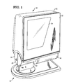
- Fig. 1 there is shown a perspective view of the optical scanner of the present invention generally indicated by the numeral 18 which comprises a box-like housing structure 20 and which includes a front cover portion 22 having located therein a transparent substrate covered aperture 24.
- the cover portion 22 is constructed of red acrylic plastic with that portion not comprising the aperture 24 being covered by any type of opaque material.
- the housing structure 20 is rotatably mounted on a support member generally indicated by the numeral 26 which includes a circular socket portion 28 to which the housing structure 20 is rotatably secured for frictional movement about the socket portion in a manner to be described more fully hereinafter.
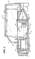
- FIG. 2 there is shown a perspective view of the scanning apparatus generally indicated by the numeral 30 with a portion of the housing structure 20 removed, within which is mounted an inner housing molded box-like structure generally indicated by the numeral 31.
- the front portion of such housing structure is open adjacent the aperture 24 (Fig. 1) of the housing structure 20.
- the inner housing box-like structure 31 which has a volume of about 1230 cubic centimetres (75 cubic inches) includes a rear floor portion 32 (Fig. 4), a right side wall portion 34 (Fig. 2), a top wall portion 33 and a bottom wall portion 35.
- the rear floor portion 32 includes a molded L-shape ledge portion 36 (Figs. 2-6 inclusive) which extends along the right side and the lower edge of the box-like structure 31 as viewed in Figs 2 and 3.
- a lens cover member 38 Secured to the ledge portion 36 by means of screws 37 (Fig. 3) is a lens cover member 38 in which is mounted a collection lens member 40.
- the front portion 39 (Fig. 4) of the cover member 38 extends in a forward direction to restrict ambient light from outside the housing structure 20 from reaching a multifaceted spinner 56 (Fig. 2) which would interfere with the light reflected by the spinner.
- a photodiode 42 Fig.
- a visible laser diode 46 for projecting a laser light beam having a wave length of 670 nm along a light path 52 (Fig. 7) to a molded routing mirror 50 which deflects the laser light beam along the light path 52 for engagement with one of eight plano reflecting mirrors 54, 59 of the spinner 56.
- the routing mirror 50 is fabricated by injection molding with the reflecting surface comprising an evaporated aluminum coating which allows the mirror to have a very small diameter of about 5 millimetres (0.200 inches).
- the routing mirror 50 is inserted into a slot 55 (Figs. 3 and 4) located in a support member 57 which is molded as part of the housing structure 30.
- the housing structures 20, 31 and the mirror 50 are molded of a polycarbonate plastic material such a POLYCARBONATE /ABS BAYBLEND which is commercially available from the Mobay Corp. of Pittsburgh, Pa., 15205-9741.
- the spinner 56 is rotatably mounted on a motor 58 which in turn is mounted on a cover member 60 secured to the rear edge portion 32 in any conventional manner such as screws 61 (Fig. 3).
- the reflecting mirrors or facets 54, 59 is set at various angles with respect to the axis of rotation of the spinner. For consecutive mirrors, the angle between the normal and the face of the mirrors and the spinner axis are 78.5, 81.5, 84.5, 87.5, 92.5, 95.5, 98.5 and 101.5 degrees with adjacent mirrors being orientated either in an upward direction (mirrors 59) (Fig. 5) or in a downward direction (mirrors 54) (Fig.
- the spinner is about 23 millimetres (0.900 inches) high and each of the mirrors 54, 59 has a width of about 16.5 millimetres (0.650 inches).
- the mirrors are placed in a sequence that provides the spinner with a natural dynamic balance.
- the spinner axis of rotation is perpendicular to the path 52 (Fig. 7) of the incident laser light beam and is offset to such path by a distance of about 15.5 millimetres (0.612 inches) or 10 degrees.
- the spinner could be fabricated from a hub and glass mirrors assembly, the preferred implementation is a fabricated part of acrylic material with injection molded optical surfaces having an evaporated aluminum coating. This reduces the cost of the spinner and since it isn't an assembly, the dynamic balance of the spinner is consistent enough to avoid the need for a balancing operation.
- the motor 58 is a 5 volt brushless DC motor which rotates the spinner 56 at a speed of approximately 3200 rpm.
- the rotation of the spinner sequentially passes each of the eight reflecting mirrors or facets 54, 59 through the laser beam path 52.
- the beam/mirror incidence angle continuously changes resulting in a reflected beam which scans through space for each of the eight mirrors.
- the resulting pattern of light generally indicated by the numeral 62 (Fig. 9) can be thought of as a set of eight distinct scan surfaces 64, 65.
- the shape of each of the scan surfaces 64, 65 is closely conic.
- the set of eight mirrors can be divided into four pairs of scan surfaces, each pair being symmetrical about a plane through the center of the spinner.
- the large pattern mirror 66 located adjacent a side wall portion 68 (Figs. 2-5 inclusive and 7) of the housing structure 31.
- the remaining four scan surfaces 54 which are orientated in a downward direction will reflect the laser light beam at a small pattern forming mirror 70 located adjacent the large pattern forming mirror 66.
- the large pattern mirror is orientated at an angle of 60 degrees to a plane passing through the light path 52 of the laser light beam deflected by the routing mirror 50 while the small pattern mirror 70 is orientated at an angle of 45 degrees. Both mirrors are mounted on the floor portion 32.
- FIG. 6 there is shown a sectional view of the cylindrical portion 44 (Fig. 3) of the housing structure 31 in which is mounted the laser diode 46.
- the laser diode 46 is shown mounted in one end of a heat sink member 72 comprising an aluminum cylinder mounted in a plate member 74.
- the heat sink member is slip fitted into the aperture 44 and held in place by two molded snap members (not shown).
- Press fitted into the front portion of the heat sink member 72 is a cylindrically shaped aluminum support member 76 for supporting a molded acrylic biconvex focusing lens 78 of 11 mm focal length.
- the support member 76 includes a 1.05 mm diameter aperture 79.
- the distance between the diode 46 and the lens 78 can be easily changed, allowing the projection optics focus to be adjusted.
- the distance is selected to allow the laser beam to come to a focus in the scanning region adjacent the aperture 24 (Fig, 1) with a spot diameter of 180 microns.
- This method of focus adjustment has two major advantages over the standard practice of using a threaded adjustment. First, the relative location of the support member 76 and the lens 78 is more stable resulting in a stable collimating beam and an easier adjustment. Second, since no threads are required between the support emitted from the lens 78 strikes the plano reflecting surface 80 of the routing mirror 50 and is deflected 90 degrees towards the pattern forming mirrors 66 and 70.
- FIG. 8 there is shown a side view of the housing structure 20 (Fig. 1) with a portion of the sidewall portion of the socket member 28 removed showing details of its construction allowing the housing structure 20 (Fig. 1) to be rotated about the socket member 28.
- the socket member 28 is comprised of a pair of clam shells 82 having one end enclosed by a side wall portion 84 (Fig. 1) and which are joined together to form a hollow cylinder 86 when mounted to the base 87 of the support member 26. Inserted into the open end of the cylinder 86 is a compressible pivot member 88 secured to cylindrically shaped lower housing portion 90 (Figs 1 and 2) of the housing structure 20.
- the pivot member 88 includes a pair of depending arm members 92 each having flexible curved end portions 94 which, when inserted into the cylinder 86, will be compressed by the inner surface 96 of the cylinder, providing a frictional drag on the cylinder when the housing structure 20 is rotated enabling the structure to be located in any position.
- FIG. 9 there is shown a plan view of the scan pattern 62 generated by the pattern forming mirrors 66, 70 (Figs. 2-5 inclusive).
- This pattern consists of eight hyperbola shaped scan lines 64, 65 having a very low curvature. This is due, in part, to the small incidence angle between the projected laser beam and the offset angle of the mirrors 54, 59 of the spinner 56 together with the offset distance of the spinner with respect to the path 52 (Fig. 7) of the projected laser beam. This offset relationship between the spinner and the beam path results in the scan lines 64, 65 not being symmetrical thereby enhancing the low curvature of the lines.
- the four scan lines 64 are generated by the mirrors 54 (Fig. 4) which are offset in a downward direction and which deflect the light beams at the pattern forming mirror 70 (Fig. 5).
- the scan lines 65 are generated by the mirrors 59 (Figs. 5 and 7) which are offset in an upward direction and which deflect the light beams at the pattern forming mirror 66 (Fig. 7).
- the angle of the mirrors 66 and 70 to each other results in the pattern of four scan lines 64 crossing the pattern of four scan lines 65 at a very low angle enabling scan pattern 62 to be projected over a very narrow scanning area.
- the laser beam outputted by the laser diode 46 (Figs. 3 and 6) will be projected along the path 52 (Fig. 7) to be deflected off the routing mirror 50, one of the mirrors 54, 59 of the spinner 56 and the pattern forming mirrors 66, 70 to scan a bar code (not shown) positioned adjacent the aperture 24 (Fig. 1) in the form of the scan pattern 62 (Fig. 9).
- the scattered light reflected from the scanned bar code label will be reflected back by the mirrors 66, 70, 54 and 59 towards the lens 40 which collects and focuses the reflected light at the photodiode 42 (Fig. 4).
- the photodiode transforms the received light intensity into electrical signals in a manner that is well known in the art.
- the photodiode 42 is positioned at the image point for a source positioned at the far end of the scanning region so as to use the spherical aberration present in the lens 40 to balance out the amount of light collected from the near and far ends of the scanning region. With this arrangement, the use of an aspheric collection lens is avoided.
- the housing structure 20 may be rotated to any position which enhances the scanning operation by the checkout operator.
Landscapes
- Engineering & Computer Science (AREA)
- Physics & Mathematics (AREA)
- Electromagnetism (AREA)
- General Engineering & Computer Science (AREA)
- Artificial Intelligence (AREA)
- Toxicology (AREA)
- General Health & Medical Sciences (AREA)
- Computer Vision & Pattern Recognition (AREA)
- General Physics & Mathematics (AREA)
- Theoretical Computer Science (AREA)
- Health & Medical Sciences (AREA)
- Mechanical Engineering (AREA)
- Mechanical Optical Scanning Systems (AREA)
Applications Claiming Priority (2)
| Application Number | Priority Date | Filing Date | Title |
|---|---|---|---|
| US07/590,202 US5192857A (en) | 1990-09-28 | 1990-09-28 | Compact optical scanner rotatable between horizontal and vertical positions |
| US590202 | 1990-09-28 |
Publications (2)
| Publication Number | Publication Date |
|---|---|
| EP0478376A2 true EP0478376A2 (de) | 1992-04-01 |
| EP0478376A3 EP0478376A3 (en) | 1992-05-20 |
Family
ID=24361269
Family Applications (1)
| Application Number | Title | Priority Date | Filing Date |
|---|---|---|---|
| EP19910308874 Withdrawn EP0478376A3 (en) | 1990-09-28 | 1991-09-27 | Optical scanner |
Country Status (3)
| Country | Link |
|---|---|
| US (1) | US5192857A (de) |
| EP (1) | EP0478376A3 (de) |
| JP (1) | JPH04333186A (de) |
Cited By (1)
| Publication number | Priority date | Publication date | Assignee | Title |
|---|---|---|---|---|
| EP0686930A1 (de) | 1994-06-08 | 1995-12-13 | Scantech B.V. | Vorrichtung zum Abtasten kodierter Information |
Families Citing this family (14)
| Publication number | Priority date | Publication date | Assignee | Title |
|---|---|---|---|---|
| US5478998A (en) * | 1993-05-10 | 1995-12-26 | Symbol Technologies, Inc. | Tilting wall-mounted optical scanner |
| US5449891A (en) * | 1993-05-10 | 1995-09-12 | Symbol Technologies, Inc. | Object sensor for an optical scanner |
| NL1003957C2 (nl) * | 1996-02-26 | 1997-08-27 | Scantech Bv | Inrichting voor het aftasten van barcodes. |
| US5988506A (en) * | 1996-07-16 | 1999-11-23 | Galore Scantec Ltd. | System and method for reading and decoding two dimensional codes of high density |
| US6083207A (en) * | 1998-12-08 | 2000-07-04 | Daig Corporation | Partitioned hemostasis valve system |
| US7015469B2 (en) * | 2003-01-09 | 2006-03-21 | Jeol Usa, Inc. | Electron holography method |
| USD493794S1 (en) | 2003-09-22 | 2004-08-03 | Symbol Technologies, Inc. | Price checker |
| US8186592B2 (en) * | 2009-12-07 | 2012-05-29 | Hand Held Products, Inc. | Universal stand for indicia readers |
| US8336780B1 (en) * | 2010-06-15 | 2012-12-25 | Webscan, Inc. | Windowed housing with rotatable imaging device |
| USD671542S1 (en) * | 2010-11-13 | 2012-11-27 | Lexmark International, Inc. | Imaging device |
| JP2012059301A (ja) * | 2011-12-21 | 2012-03-22 | Nec Infrontia Corp | セルフposシステム |
| US9070007B2 (en) | 2013-01-11 | 2015-06-30 | Datalogic ADC, Inc. | Adjustable data reader with pivot mount |
| USD735197S1 (en) * | 2014-03-26 | 2015-07-28 | Optoelectronics Co., Ltd. | Optical information reader |
| USD760719S1 (en) | 2014-10-20 | 2016-07-05 | Hand Held Products, Inc. | Scanner |
Family Cites Families (22)
| Publication number | Priority date | Publication date | Assignee | Title |
|---|---|---|---|---|
| US4043632A (en) * | 1975-05-27 | 1977-08-23 | Data General Corporation | Scanning polygon with adjustable mirrors |
| US4194126A (en) * | 1978-03-06 | 1980-03-18 | Hall & Myers | Escort memory using mirrors |
| JPS56164312A (en) * | 1980-05-22 | 1981-12-17 | Konishiroku Photo Ind Co Ltd | Optical deflecting device |
| US4575625A (en) * | 1983-09-27 | 1986-03-11 | Knowles Carl H | Integral hand-held laser scanner |
| US4753498A (en) * | 1985-03-22 | 1988-06-28 | Tokyo Kogaku Kikai Kabushiki Kaisha | Optical reader |
| US4797551A (en) * | 1987-06-11 | 1989-01-10 | Ncr Corporation | Compact laser scanner optical system |
| JPH0521133Y2 (de) * | 1987-06-11 | 1993-05-31 | ||
| JPH0823629B2 (ja) * | 1987-08-19 | 1996-03-06 | 富士通株式会社 | 光学読取装置 |
| US4762984A (en) * | 1987-09-11 | 1988-08-09 | Metrologic Instruments, Inc. | Laser scanner apparatus with adjustable mount for connectors |
| KR910008387B1 (ko) * | 1987-09-22 | 1991-10-15 | 도오또오 덴끼 가부시끼가이샤 | 상품데이터 판독장치 |
| US4853521A (en) * | 1987-12-28 | 1989-08-01 | Claeys Ronald W | System for verifying and recording drug administration to a patient |
| US4871904A (en) * | 1987-12-28 | 1989-10-03 | Symbol Technologies, Inc. | Multidirectional optical scanner |
| US4840083A (en) * | 1988-03-14 | 1989-06-20 | Elco Industries, Inc. | Device for dampening rotary motion |
| US4944481A (en) * | 1988-06-30 | 1990-07-31 | Next, Inc. | Balanced monitor stand |
| JP2771593B2 (ja) * | 1989-04-20 | 1998-07-02 | 富士通株式会社 | 光走査装置 |
| US4939356A (en) * | 1989-05-02 | 1990-07-03 | Spectra-Physics, Inc. | Bar code scanner with asterisk scan pattern |
| JP2695468B2 (ja) * | 1989-05-24 | 1997-12-24 | 株式会社テック | 商品データ読取装置 |
| US4971410A (en) * | 1989-07-27 | 1990-11-20 | Ncr Corporation | Scanning and collection system for a compact laser |
| JPH0821056B2 (ja) * | 1989-09-12 | 1996-03-04 | 日本電装株式会社 | バーコード読取装置 |
| US4967076A (en) * | 1989-12-08 | 1990-10-30 | Ncr Corporation | Optical scanner producing multiple scan patterns |
| US5108062A (en) * | 1990-09-28 | 1992-04-28 | Ncr Corporation | Pivot apparatus |
| USD325729S (en) | 1990-09-28 | 1992-04-28 | Ncr Corporation | Optical scanner or similar article |
-
1990
- 1990-09-28 US US07/590,202 patent/US5192857A/en not_active Expired - Lifetime
-
1991
- 1991-09-26 JP JP3273585A patent/JPH04333186A/ja active Pending
- 1991-09-27 EP EP19910308874 patent/EP0478376A3/en not_active Withdrawn
Cited By (4)
| Publication number | Priority date | Publication date | Assignee | Title |
|---|---|---|---|---|
| EP0686930A1 (de) | 1994-06-08 | 1995-12-13 | Scantech B.V. | Vorrichtung zum Abtasten kodierter Information |
| NL9400924A (nl) * | 1994-06-08 | 1996-01-02 | Scantech Bv | Inrichting voor het aftasten van gecodeerde informatie. |
| US5834751A (en) * | 1994-06-08 | 1998-11-10 | Scantech B.V. | Mounting arrangement for scanner |
| EP0686930B1 (de) * | 1994-06-08 | 2004-02-11 | Scantech-ID Holding B.V. | Vorrichtung zum Abtasten kodierter Information |
Also Published As
| Publication number | Publication date |
|---|---|
| US5192857A (en) | 1993-03-09 |
| EP0478376A3 (en) | 1992-05-20 |
| JPH04333186A (ja) | 1992-11-20 |
Similar Documents
| Publication | Publication Date | Title |
|---|---|---|
| US6460767B1 (en) | Optical scanner for omni-directional scanning of code symbols within a scanning volume | |
| US5214270A (en) | Modular handheld or fixed scanner | |
| US5073702A (en) | Multiple beam bar code scanner | |
| US5192857A (en) | Compact optical scanner rotatable between horizontal and vertical positions | |
| EP0490604B1 (de) | Optisches Abtastgerät | |
| KR100329535B1 (ko) | 광학주사장치 | |
| EP0318574B1 (de) | Optisches ablesegerät | |
| US5179271A (en) | Compact optical scan pattern generator for bar code reading systems | |
| US5175421A (en) | Dual depth of field deflector for bar code scanners | |
| US6412696B1 (en) | Countertop projection laser scanning system for omnidirectional scanning of code symbols within a narrowly-confined scanning volume projected above a countertop surface | |
| WO1989005013A1 (en) | Optical scanning apparatus | |
| US20010017320A1 (en) | Projection laser scanner for scanning bar codes within a confined scanning volume | |
| WO1994001835A1 (en) | Multiple plane scanning system for data reading applications | |
| JPH0823629B2 (ja) | 光学読取装置 | |
| US5043563A (en) | Portable overhead bar code scanner | |
| US5081364A (en) | Multifocal scanning system | |
| EP0373934A2 (de) | Handlesegerät für Strichkodes | |
| EP0533366A2 (de) | Gerät und Verfahren für optisches Abtasten | |
| EP0533383A2 (de) | Optische Abtastvorrichtung | |
| EP0539054A1 (de) | Anlage für optische Abtastung | |
| EP0528630A2 (de) | Optisches Abtastgerät |
Legal Events
| Date | Code | Title | Description |
|---|---|---|---|
| PUAI | Public reference made under article 153(3) epc to a published international application that has entered the european phase |
Free format text: ORIGINAL CODE: 0009012 |
|
| AK | Designated contracting states |
Kind code of ref document: A2 Designated state(s): DE FR GB |
|
| PUAL | Search report despatched |
Free format text: ORIGINAL CODE: 0009013 |
|
| AK | Designated contracting states |
Kind code of ref document: A3 Designated state(s): DE FR GB |
|
| 17P | Request for examination filed |
Effective date: 19921026 |
|
| STAA | Information on the status of an ep patent application or granted ep patent |
Free format text: STATUS: THE APPLICATION HAS BEEN WITHDRAWN |
|
| 18W | Application withdrawn |
Withdrawal date: 19930310 |