-
The present invention relates to optical scanning apparatus of the kind for reading bar code symbols on objects passing adjacent the scanning apparatus.
-
In present-day merchandising point-of-sale operations, data pertaining to the purchase of a merchandise item is obtained by reading data encoded indicia or symbols such as a bar code printed on the merchandise item. In order to standardize the bar codes used in various point-of-sale checkout systems, the grocery industry has adapted a uniform product code (UPC) which is in the form of a bar code. Various reading systems have been constructed to read this type of bar code, including stationary optical reader systems normally located within the checkout counter in which the bar code is read by projecting a plurality of scanning light beams through a window constituting the scanning area of the counter over which the bar code printed on a purchased merchandise item or on a bar code label attached to the merchandise item is moved.
-
A scanning system of this kind is disclosed in US Patent No. 4,797,551. This known scanning apparatus has the disadvantages of a large and bulky construction and of inflexibility in use, in that merchandise items must always be passed over the scanning apparatus with the bar code orientated in a downward direction.
-
It is an object of the present invention to provide a scanning apparatus of the kind specified which is versatile in operation.
-
Therefore according to the present invention, there is provided optical scanning apparatus for reading bar code symbols on objects passing adjacent said scanning apparatus, including a housing assembly having an aperture contained therein, and a scanning apparatus mounted within said housing member adjacent said aperture and adapted to project scanning light beams through said aperture for scanning bar code symbols positioned adjacent said aperture, characterized by a support member, and pivot means secured to said housing assembly and rotatably mounted in said support member for rotatably positioning said housing assembly in a plurality of scanning positions.
-
It will be appreciated that optical scanning apparatus according to the immediately preceding paragraph has the advantage that the housing assembly can be positioned vertically or horizontally on either side of the vertical, whereby merchandise items can be scanned by passing the items either under or over, or by a side of the scanner, as is convenient, so that a highly versatile, adjustable scanner is provided.
-
According to a second aspect of the present invention, there is provided optical scanning apparatus for reading bar code symbols on objects passing adjacent said scanning apparatus, characterized in that said housing assembly includes a housing member having a floor portion and oppositely located first and second wall portions located adjacent said aperture and a third wall portion extending between said first and second wall portions; a source of a coherent light beam mounted in said third wall portion and adapted to project said light beam along said floor portion of said housing assembly; first light deflecting means mounted on said floor portion and adapted to project the projected light beam along a first light path; scanning means mounted on said floor portion adjacent said second wall portion and in said first light path and adapted to cyclically sweep the light beam along a plurality of second light paths; second light deflecting means mounted adjacent said floor portion and in said second light paths and adapted to deflect the light beams in said second light paths along a plurality of third light paths through said aperture in the form of a scanning pattern for scanning a bar code label positioned adjacent said aperture; a lens member positioned adjacent said first light deflecting means and said first wall portion and adapted to collect the light beams reflected from the scanned bar code label and to direct the collected light beams along a fourth light path; and detecting means mounted in said first wall portion and in said fourth light path and adapted to generate electrical signals in response to receiving the collected light beams from said lens member.
-
Recent developments in merchandise packaging have led to the introduction of bar code labels which are long and narrow, requiring that the bar code label be oriented in a predetermined position to allow the scanning apparatus to effectively read the bar code label. Since the merchandise items on which the narrow bar code label has been affixed are small in size, the reading of this type of label has proved troublesome.
-
Optical scanning apparatus according to the second aspect of the invention provides a scanner which has a compact construction, and which has the capability of generating a scanning pattern which enables a small size merchandise item having a long and narrow width bar code to be easily scanned.
-
One embodiment of the present invention will now be described, by way of example, with references to the accompanying drawings, in which:-
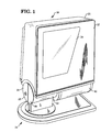
- Fig. 1 is a perspective view of the optical scanner of the present invention;
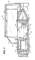
- Fig. 2 is a perspective view similar to Fig. 1 with a portion of the outer housing cover removed showing details of the compact scanning apparatus of the present invention;
- Fig. 3 is a side detailed view of the scanning apparatus of the present invention;
- Fig. 4 is a sectional view taken on lines 4-4 of Fig. 3 showing the optical elements of the scanning apparatus;
- Fig. 5 is a sectional view taken on lines 5-5 of Fig. 3 showing the orientation of the pattern forming mirrors;
- Fig. 6 is a sectional view taken on lines 6-6 of Fig. 3 showing details of the mounting of the laser diode and the focusing lens;
- Fig. 7 is an enlarged right side perspective view of the scanning apparatus showing the light path of the scanning light beams as they are reflected from the spinner to the pattern forming mirrors;
- Fig. 8 is a side view of the scanning apparatus shown in Fig. 1 showing details of the pivot mechanism for rotating the housing structure between horizontal and vertical positions; and
- Fig. 9 is a plan view of the scan pattern generated by the pattern forming mirrors.
-
Referring now to Fig. 1 there is shown a perspective view of the optical scanner of the present invention generally indicated by the numeral 18 which comprises a box-like housing structure 20 and which includes a front cover portion 22 having located therein a transparent substrate covered aperture 24. In the present embodiment, the cover portion 22 is constructed of red acrylic plastic with that portion not comprising the aperture 24 being covered by any type of opaque material. The housing structure 20 is rotatably mounted on a support member generally indicated by the numeral 26 which includes a circular socket portion 28 to which the housing structure 20 is rotatably secured for frictional movement about the socket portion in a manner to be described more fully hereinafter.
-
Referring now to Fig. 2 there is shown a perspective view of the scanning apparatus generally indicated by the numeral 30 with a portion of the housing structure 20 removed, within which is mounted an inner housing molded box-like structure generally indicated by the numeral 31. The front portion of such housing structure is open adjacent the aperture 24 (Fig. 1) of the housing structure 20. As best seen from Figs 2-6 inclusive, the inner housing box-like structure 31 which has a volume of about 1230 cubic centimetres (75 cubic inches) includes a rear floor portion 32 (Fig. 4), a right side wall portion 34 (Fig. 2), a top wall portion 33 and a bottom wall portion 35.
-
The rear floor portion 32 includes a molded L-shape ledge portion 36 (Figs. 2-6 inclusive) which extends along the right side and the lower edge of the box-like structure 31 as viewed in Figs 2 and 3. Secured to the ledge portion 36 by means of screws 37 (Fig. 3) is a lens cover member 38 in which is mounted a collection lens member 40. The front portion 39 (Fig. 4) of the cover member 38 extends in a forward direction to restrict ambient light from outside the housing structure 20 from reaching a multifaceted spinner 56 (Fig. 2) which would interfere with the light reflected by the spinner. Mounted in the rear portion of the lens cover member adjacent the lowest surface of the ledge portion 36 is a photodiode 42 (Fig. 4) for generating electrical signals in response to receiving the reflected light beams from the scanned bar code label and which is collected by the collection lens member 40 and focused at a point at which the photodiode is located. As best seen in mounted a visible laser diode 46 (Fig. 6) for projecting a laser light beam having a wave length of 670 nm along a light path 52 (Fig. 7) to a molded routing mirror 50 which deflects the laser light beam along the light path 52 for engagement with one of eight plano reflecting mirrors 54, 59 of the spinner 56. The routing mirror 50 is fabricated by injection molding with the reflecting surface comprising an evaporated aluminum coating which allows the mirror to have a very small diameter of about 5 millimetres (0.200 inches). This small diameter of the mirror 50 allows more of the reflected light to pass around it for collection by the collection lens 40. The routing mirror 50 is inserted into a slot 55 (Figs. 3 and 4) located in a support member 57 which is molded as part of the housing structure 30. The housing structures 20, 31 and the mirror 50 are molded of a polycarbonate plastic material such a POLYCARBONATE /ABS BAYBLEND which is commercially available from the Mobay Corp. of Pittsburgh, Pa., 15205-9741.
-
As best seen in Fig. 4, the spinner 56 is rotatably mounted on a motor 58 which in turn is mounted on a cover member 60 secured to the rear edge portion 32 in any conventional manner such as screws 61 (Fig. 3). The reflecting mirrors or facets 54, 59 is set at various angles with respect to the axis of rotation of the spinner. For consecutive mirrors, the angle between the normal and the face of the mirrors and the spinner axis are 78.5, 81.5, 84.5, 87.5, 92.5, 95.5, 98.5 and 101.5 degrees with adjacent mirrors being orientated either in an upward direction (mirrors 59) (Fig. 5) or in a downward direction (mirrors 54) (Fig. 4) with oppositely mounted mirrors being mounted in the same direction (Fig.4). The spinner is about 23 millimetres (0.900 inches) high and each of the mirrors 54, 59 has a width of about 16.5 millimetres (0.650 inches). The mirrors are placed in a sequence that provides the spinner with a natural dynamic balance. The spinner axis of rotation is perpendicular to the path 52 (Fig. 7) of the incident laser light beam and is offset to such path by a distance of about 15.5 millimetres (0.612 inches) or 10 degrees. Although the spinner could be fabricated from a hub and glass mirrors assembly, the preferred implementation is a fabricated part of acrylic material with injection molded optical surfaces having an evaporated aluminum coating. This reduces the cost of the spinner and since it isn't an assembly, the dynamic balance of the spinner is consistent enough to avoid the need for a balancing operation.
-
The motor 58 is a 5 volt brushless DC motor which rotates the spinner 56 at a speed of approximately 3200 rpm. The rotation of the spinner sequentially passes each of the eight reflecting mirrors or facets 54, 59 through the laser beam path 52. As a mirror passes through the beam, the beam/mirror incidence angle continuously changes resulting in a reflected beam which scans through space for each of the eight mirrors. The resulting pattern of light generally indicated by the numeral 62 (Fig. 9) can be thought of as a set of eight distinct scan surfaces 64, 65. The shape of each of the scan surfaces 64, 65 is closely conic. The set of eight mirrors can be divided into four pairs of scan surfaces, each pair being symmetrical about a plane through the center of the spinner. Four of the scan surfaces 59 which are orientated in an upward direction will reflect the laser light beam in a direction which strikes a large pattern mirror 66 located adjacent a side wall portion 68 (Figs. 2-5 inclusive and 7) of the housing structure 31. The remaining four scan surfaces 54 which are orientated in a downward direction will reflect the laser light beam at a small pattern forming mirror 70 located adjacent the large pattern forming mirror 66. As best seen from Fig. 5, the large pattern mirror is orientated at an angle of 60 degrees to a plane passing through the light path 52 of the laser light beam deflected by the routing mirror 50 while the small pattern mirror 70 is orientated at an angle of 45 degrees. Both mirrors are mounted on the floor portion 32.
-
Referring to Fig. 6, there is shown a sectional view of the cylindrical portion 44 (Fig. 3) of the housing structure 31 in which is mounted the laser diode 46. The laser diode 46 is shown mounted in one end of a heat sink member 72 comprising an aluminum cylinder mounted in a plate member 74. The heat sink member is slip fitted into the aperture 44 and held in place by two molded snap members (not shown). Press fitted into the front portion of the heat sink member 72 is a cylindrically shaped aluminum support member 76 for supporting a molded acrylic biconvex focusing lens 78 of 11 mm focal length. The support member 76 includes a 1.05 mm diameter aperture 79. By mounting the support member 76 in the heat sink 72, the distance between the diode 46 and the lens 78 can be easily changed, allowing the projection optics focus to be adjusted. The distance is selected to allow the laser beam to come to a focus in the scanning region adjacent the aperture 24 (Fig, 1) with a spot diameter of 180 microns. This method of focus adjustment has two major advantages over the standard practice of using a threaded adjustment. First, the relative location of the support member 76 and the lens 78 is more stable resulting in a stable collimating beam and an easier adjustment. Second, since no threads are required between the support emitted from the lens 78 strikes the plano reflecting surface 80 of the routing mirror 50 and is deflected 90 degrees towards the pattern forming mirrors 66 and 70.
-
Referring to Fig. 8, there is shown a side view of the housing structure 20 (Fig. 1) with a portion of the sidewall portion of the socket member 28 removed showing details of its construction allowing the housing structure 20 (Fig. 1) to be rotated about the socket member 28. The socket member 28 is comprised of a pair of clam shells 82 having one end enclosed by a side wall portion 84 (Fig. 1) and which are joined together to form a hollow cylinder 86 when mounted to the base 87 of the support member 26. Inserted into the open end of the cylinder 86 is a compressible pivot member 88 secured to cylindrically shaped lower housing portion 90 (Figs 1 and 2) of the housing structure 20. The pivot member 88 includes a pair of depending arm members 92 each having flexible curved end portions 94 which, when inserted into the cylinder 86, will be compressed by the inner surface 96 of the cylinder, providing a frictional drag on the cylinder when the housing structure 20 is rotated enabling the structure to be located in any position.
-
Referring now to Fig. 9, there is shown a plan view of the scan pattern 62 generated by the pattern forming mirrors 66, 70 (Figs. 2-5 inclusive). This pattern consists of eight hyperbola shaped scan lines 64, 65 having a very low curvature. This is due, in part, to the small incidence angle between the projected laser beam and the offset angle of the mirrors 54, 59 of the spinner 56 together with the offset distance of the spinner with respect to the path 52 (Fig. 7) of the projected laser beam. This offset relationship between the spinner and the beam path results in the scan lines 64, 65 not being symmetrical thereby enhancing the low curvature of the lines. These scan lines also have an angular spacing of between three and five degrees allowing for the complete scanning of high aspect ratio truncated bar code labels during which scanning the bar code label may be rotated more than thirty degrees. The four scan lines 64 are generated by the mirrors 54 (Fig. 4) which are offset in a downward direction and which deflect the light beams at the pattern forming mirror 70 (Fig. 5). The scan lines 65 are generated by the mirrors 59 (Figs. 5 and 7) which are offset in an upward direction and which deflect the light beams at the pattern forming mirror 66 (Fig. 7). The angle of the mirrors 66 and 70 to each other results in the pattern of four scan lines 64 crossing the pattern of four scan lines 65 at a very low angle enabling scan pattern 62 to be projected over a very narrow scanning area.
-
The laser beam outputted by the laser diode 46 (Figs. 3 and 6) will be projected along the path 52 (Fig. 7) to be deflected off the routing mirror 50, one of the mirrors 54, 59 of the spinner 56 and the pattern forming mirrors 66, 70 to scan a bar code (not shown) positioned adjacent the aperture 24 (Fig. 1) in the form of the scan pattern 62 (Fig. 9). The scattered light reflected from the scanned bar code label will be reflected back by the mirrors 66, 70, 54 and 59 towards the lens 40 which collects and focuses the reflected light at the photodiode 42 (Fig. 4). The photodiode transforms the received light intensity into electrical signals in a manner that is well known in the art. The photodiode 42 is positioned at the image point for a source positioned at the far end of the scanning region so as to use the spherical aberration present in the lens 40 to balance out the amount of light collected from the near and far ends of the scanning region. With this arrangement, the use of an aspheric collection lens is avoided. Depending on the location and conditions of the checkout station, the housing structure 20 may be rotated to any position which enhances the scanning operation by the checkout operator.