EP0446364B1 - Laser scanner for bar code reader - Google Patents
Laser scanner for bar code reader Download PDFInfo
- Publication number
- EP0446364B1 EP0446364B1 EP90913548A EP90913548A EP0446364B1 EP 0446364 B1 EP0446364 B1 EP 0446364B1 EP 90913548 A EP90913548 A EP 90913548A EP 90913548 A EP90913548 A EP 90913548A EP 0446364 B1 EP0446364 B1 EP 0446364B1
- Authority
- EP
- European Patent Office
- Prior art keywords
- scanning
- laser beam
- holograms
- support member
- bar code
- Prior art date
- Legal status (The legal status is an assumption and is not a legal conclusion. Google has not performed a legal analysis and makes no representation as to the accuracy of the status listed.)
- Expired - Lifetime
Links
Images


Classifications
-
- G—PHYSICS
- G06—COMPUTING OR CALCULATING; COUNTING
- G06K—GRAPHICAL DATA READING; PRESENTATION OF DATA; RECORD CARRIERS; HANDLING RECORD CARRIERS
- G06K7/00—Methods or arrangements for sensing record carriers, e.g. for reading patterns
- G06K7/10—Methods or arrangements for sensing record carriers, e.g. for reading patterns by electromagnetic radiation, e.g. optical sensing; by corpuscular radiation
- G06K7/10544—Methods or arrangements for sensing record carriers, e.g. for reading patterns by electromagnetic radiation, e.g. optical sensing; by corpuscular radiation by scanning of the records by radiation in the optical part of the electromagnetic spectrum
- G06K7/10821—Methods or arrangements for sensing record carriers, e.g. for reading patterns by electromagnetic radiation, e.g. optical sensing; by corpuscular radiation by scanning of the records by radiation in the optical part of the electromagnetic spectrum further details of bar or optical code scanning devices
- G06K7/10861—Methods or arrangements for sensing record carriers, e.g. for reading patterns by electromagnetic radiation, e.g. optical sensing; by corpuscular radiation by scanning of the records by radiation in the optical part of the electromagnetic spectrum further details of bar or optical code scanning devices sensing of data fields affixed to objects or articles, e.g. coded labels
- G06K7/10871—Methods or arrangements for sensing record carriers, e.g. for reading patterns by electromagnetic radiation, e.g. optical sensing; by corpuscular radiation by scanning of the records by radiation in the optical part of the electromagnetic spectrum further details of bar or optical code scanning devices sensing of data fields affixed to objects or articles, e.g. coded labels randomly oriented data-fields, code-marks therefore, e.g. concentric circles-code
Definitions
- the present invention relates to bar code reading apparatus.
- Laser scanners are extensively used in point-of-sale (POS) systems at supermarkets, department stores, and other speciality stores for reading bar codes. These stores usually use a stand-type laser scanner, as it is relatively small and occupies little space.
- the stand-type laser scanner is compact and takes up little space, and thus is suitable for a small store having only a small space for a check-out counter.
- a conventional stand-type scanner has a scanning optical system incorporated in a support unit 5 protruding from a substrate (a base plate) 6 arranged on a counter 9.
- This arrangement usually increases the size of the support unit, and accordingly the size of the scanner as a whole, and spoils the appearance thereof.
- a support 7 blocks the sight of a customer B, who therefore cannot clearly see a bar code 10 on a commodity 8.
- the conventional stand-type laser scanner is not transparent and is located between the customer and the operator, and thus the customer cannot see or read the bar code on the commodity through the stand-type laser scanner and must shift his or her position to see the bar code.
- P denotes a scanning beam emitted in the direction of an arrow mark.
- Another conventional bar code reading apparatus for reading a bar code on an object may be considered to comprise: a laser source for emitting a laser beam; laser beam scanning means for deriving from the emitted laser beam a scanning beam which passes out of the apparatus, via a light emission window, towards the object and scans in a predetermined scanning pattern across the bar code on the object; and optical detecting means for detecting light reflected back towards the apparatus from the bar code; the said laser beam scanning means and the said optical detecting means both being incorporated in a base unit of the apparatus, and the said light emission window being supported on the base unit by a support member.
- the scanning optical system is incorporated in the base unit, rather than being in the external support unit above the base unit as in Figs. 30 and 31.
- the support member still blocks the customer's view of the bar code.
- Figure 32 shows a typical check-out counter according to another prior art.
- Such bar code reading apparatus has a reduced size and can enable a customer to easily observe the bar code reading operation. Because the support member is transparent, it does not spoil the appearance of the apparatus. In addition, the support member external to the base unit does not incorporate the scanning optical system, and thus the support member is compact. A customer can easily observe and confirm a bar code operation through the transparent support member.
- EP-A-0194115 discloses a hand-held bar code reading apparatus in which the outgoing and incoming light can pass through a transparent housing portion.
- the transparent support member may be a light guide plate in which the outgoing light and returning signal light repeat a total reflection and are propagated in the light guide plate.
- the diffracting direction(s) of the scanning beam(s) can be selected readily, and by controlling the scanning direction(s) in this way the bar code can be easily read.
- the laser beam scanning means may be either a galvanomirror or a rotatable polygonal mirror.
- the apparatus further comprises a reflection-type hologram provided on the said support member to reflect, in a predetermined direction, only a specific wavelength of light, and an indicator, located on the side of the support member that is opposite the side on which the said light emission window is located, for displaying information; the indicator producing light having a wavelength substantially identical to the said specific wavelength, so that such light from the indicator is reflected by the said reflection-type hologram and appears, to a viewer positioned on the same side of the said support member as the indicator, to have originated from a position close to the bar code.
- the wavelength of the laser beam preferably differs from that of the light produced by the indicator.
- the support member is removably fitted to the base unit.
- a laser beam dividing means for dividing an outgoing laser beam from the laser source into a plurality of laser beams that are made incident on respective holograms of the light emission window.
- the laser beam dividing means is preferably composed of a plurality of reflection type holograms.
- the laser source may be a semiconductor laser.
- FIGS 1 and 2 show a basic arrangement of a stand type laser scanner according to an embodiment of the present invention.
- a transparent light guide plate (support member) 23 is integrally formed on a substrate (base unit) 20, and a scanning beam emission window 25 is formed at an upper part of the light guide plate.
- the emission window 25 is formed from a hologram 27.
- the transparent light guide plate 23 serves to support the emission window 25.
- the upper part of the light guide plate may be curved to this side (the side of the operator) as shown in the figures, so that a scanning beam P always irradiates a bar code (B in Fig. 34) of a commodity 8.
- the substrate 20 incorporates a scanning optical system for the scanning beam P.
- This scanning optical system has, for example, a polygonal mirror (rotatable polygonal mirror) 31 known per se rotated around a rotary shaft 33 by a motor 35.
- the polygonal mirror 31 guides the beam P in a plane of the substrate 20 so that the beam is reflected upward from a lower mirror 37a into the transparent light guide plate 23.
- the scanning beam repeats a total reflection inside the transparent light guide plate 23, and as shown in the figures, is diffracted by the hologram 27 in a predetermined direction and emitted from the emission window 25.
- the emitting direction is optionally set according to the design of a pitch of interference fringes, etc., of the hologram 27.
- a light source of the scanning beam P is, for example, a semiconductor laser 41 (Fig. 2).
- the beam is made incident on the polygonal mirror 31 from, for example, the inside of the substrate 20.
- This embodiment is characterized in that the light guide plate 23 forming the support of the emission window 25 is transparent, and that optical systems (the scanning optical system, etc.,) except for the emission window 25 are integrally incorporated inside the substrate 20.
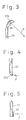
- Figure 3 shows another embodiment of the invention.
- a reflection mirror 37b is fitted to an upper part of the transparent light guide plate 23, and the reflection mirror 37b reflects the scanning beam P out through the emission window 25.
- the hologram 27 is not needed at the emission window 25.
- the reflection mirror 37b is fixed to the upper end (opposite to the commodity) of the transparent light guide plate 23 by adhesion or vapor deposition.
- Figure 4 shows still another embodiment of the invention.
- a lower end face 23a of the transparent light guide 23 is obliquely cut. Without the lower reflection mirror 37a of Fig. 2, the lower end face 23a directly entirely reflects a scanning beam upward into the transparent light guide plate 23.
- a hologram 38 may be arranged at a lower end portion of the transparent light guide 23.
- the hologram 38 diffracts the scanning beam P from the polygonal mirror 31 (Fig. 2) in a predetermined direction to guide the beam upward into the transparent light guide plate 23.
- FIG. 6 shows a laser beam scanning and signal light collecting optical system according to an embodiment of the present invention.
- a laser source 41 an He-Ne laser or a semiconductor laser
- emits a light beam which is converted by a beam shaping lens 43 into a beam having a predetermined diameter and shape.
- the beam enters the polygonal mirror 31, and due to the rotation of the polygonal mirror 31 around the shaft 33, the beam becomes the scanning beam P which enters the transparent light guide plate 23.
- the beam P traces the scanning beam path mentioned before.
- the beam scanning the bar code B (Fig. 34) of the commodity 8 is accordingly scattered, and part of the scattered light again enters, as signal light S, the transparent light guide plate 23.
- the signal light S traces the same path as before and returns to the polygonal mirror 31.
- the signal light S is then reflected by the polygonal mirror 31 and by a holed concave mirror 49, and guided to a photodetector 51.
- the processes carried out after the detection of the signal light by the photodetector 51 are not the object of the invention and are well known, and therefore, a detailed explanation thereof is omitted.
- the size and position of a pinhole 49a of the holed concave mirror 49 are set so as not to interfere with a beam traveling toward the polygonal mirror 31.
- the scanning optical system is incorporated in the substrate 20 but not disposed inside the transparent light guide plate 23, and thus the transparent light guide 23 may have a compact design.
- a customer can easily observe a reading operation of the bar code B from the back of and through the transparent light guide plate 23.
- the light source need not be incorporated inside the substrate 20 but can be located outside the substrate, and an outgoing beam from the outside light source guided into the substrate.
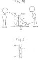
- Figures 9 to 11 show an embodiment which enables a customer to observe a bar code B of a commodity as well as a price display.
- the scanning optical system (such as the polygonal mirror 31 and mirror 37a) incorporated inside the substrate 20 provides a scanning beam, which is propagated inside the light guide plate 23 in parallel and externally emitted from the emission window 25 in a predetermined direction. Since the support portion is transparent, a customer can observe a bar code but cannot simultaneously observe a price display. This is because the price display is usually oriented toward an operator, and thus cannot be seen by the customer. According to the embodiment of Figs. 9 to 11, a display (an indicator) 53 is arranged on the substrate 20 and oriented toward the operator, but information displayed on the display can be seen by a customer positioned behind the display.
- FIGs 9, 10, and 11 show a basic arrangement of the stand type laser scanner according to the embodiment of the invention.
- a transparent light guide 23 is fitted on a substrate 20.
- a scanning beam emission window 25 composed of a hologram 27 is fitted to an upper part of the light guide plate.
- the substrate 20 incorporates a scanning optical system having a polygonal mirror 31 rotated by a motor 35 (Fig. 2). In response to the rotation, the polygonal mirror 31 guides a beam in a plane of the substrate 20. The beam is guided by a reflection mirror 37a (Fig. 2) upward into the transparent light guide plate 23.
- the scanning beam inside the transparent light guide plate 23 repeats a total reflection, and as shown in the figures, is diffracted by and emitted from the emission window (hologram) 25 in a predetermined direction to irradiate a bar code.
- a reflection type hologram 42 is formed at the back thereof, i.e., the customer's side opposite to the emission window 25.
- a price indicator (display) 53 is integrally obliquely arranged on the substrate 20 on the same side as the reflection type hologram 42, to face the reflection type hologram 42 of the transparent light guide plate 23.
- the reflection type hologram has diffraction characteristics of reflecting light having a specific wavelength, and the diffraction characteristics can be optionally controlled by properly designing a pitch of the hologram (interference fringes), etc.
- information light L (Fig. 10) from the price indicator 53 is reflected and diffracted by the reflection type hologram 42 in a predetermined direction, to be able to be seen by a customer.
- the customer can see a virtual image of a price (Yen 123 in the figure) on the indicator 53 as well as a bar code B on a commodity handled by the operator.
- This principle is the same as the principle of a headup display that overlays information light (corresponding to the price information) over a background (corresponding to the bar code of the commodity).
- the color of the information light L of the indicator 53 preferably matches the color, for example, green, of light (having the particular wavelength) reflected from the reflection type hologram 42.
- the scanning beam P propagated in the transparent light guide plate 23 also enters the reflection type hologram 42 for the indicator. If the wavelength of the scanning beam P is selected to be different (for example, red) from the selected wavelength of the reflection type hologram 42, it will not be affected by the reflection type hologram 42. Namely, as if the reflection type hologram 42 were omitted, the scanning beam is propagated upward by a repetitive total reflection in the transparent light guide plate 23.
- the hologram 42 may be formed at either side of the light guide plate.
- the price information light L from the indicator 53 is reflected and diffracted by the reflection type hologram 42 in a predetermined direction, so that a virtual image of the information substantially overlaps a bar code of a commodity positioned behind the transparent light guide plate 23. Namely, as in the headup display, a customer can observe the bar code as well as the price information light, one upon the other, without shifting position.
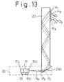
- Figures 12 to 17B show embodiments which read a bar code B by using a plurality of crossing scanning line patterns.
- scanning line patterns that cross and are oriented in at least two directions. If only one scanning line is used, the scanning line may not impinge on the bar code, depending on the orientation of the commodity (bar code) handled by an operator, and as a result, the bar code cannot be read. This frequently happens when the bar code is small. For a very small bar code, at least three to five multidirectional crossing patterns are needed.
- FIGs. 1 to 11 basically employ a single (unidirectional) scanning line.
- Figures 12 and 13 show an embodiment of a stand type laser scanner employing multiple scanning lines.
- a transparent light guide plate 23 is integrally formed on a substrate 20 (Fig. 13), and a scanning beam emission window 25 is formed at an upper part of the light guide plate.
- the emission window 25 has a plurality of holograms H1, H2, and H3 arranged vertically on a substantially vertical plane.
- the substrate 20 incorporates a scanning optical system having a polygonal mirror 31 rotated by a motor 35. In response to the rotation, the polygonal mirror 31 guides a beam in a plane of the substrate 20. The beam is guided upward by a lower end face 23a of the transparent light guide plate 23 into the guide plate.
- the scanning beam in the transparent light guide plate 23 repeats a total reflection, and as shown in the figures, is diffracted by and emitted from the emission window 25 in predetermined directions.
- the emission directions can be set by properly designing the pitches of interference fringes of the holograms H1, H2, and H3.
- numeral 41 denotes a semiconductor laser serving as a light source.
- the scanning beam from the polygonal mirror 31 is propagated upward in the transparent light guide plate 23 due to the repetitive total reflection.
- the holograms H1, H2, and H3 receive the coherent scanning beam and emit beams in respective diffraction directions D1, D2, and D3 as shown in Fig. 13.
- the middle hologram H2 for example, does not turn (twist) the scanning direction by diffraction but provides a scanning beam b that is in parallel with the incident scanning beam P.
- the holograms H1 and H3 provide twisted scanning lines a and c due to the diffraction, Namely, the scanning lines a, b, and c form three scanning line patterns crossing one another.
- the unidirectional scan (parallel scan) in the transparent light guide plate 23 is converted by the holograms H1, H2, and H3 into the scanning patterns of three directions crossing one another.
- the scanning lines a and c are not twisted sufficiently and substantially in parallel with each other.
- a bar code reading operation with the stand type scanner is usually carried out, however, by putting a bar code (a commodity) on a table so that a region to be read is close to the surface of the table which is spaced from the holograms by a certain distance.
- the cross pattern scanning method of the invention therefore, raises no problems in practical use.
- the number of scanning lines can be increased infinitely in theory, by increasing the number of holograms, to thereby realize an all-round reading.
- angles of the reflection surfaces 31a, 31b, ..., 31i of the polygonal mirror 31 may be made slightly different from one another, to separate a scanning beam in parallel so that coherent incident scanning beams for the respective holograms are easily formed as shown in Fig. 13.
- Figures 14A and 14B schematically show the way of forming the hologram H2 that produces the untwisted scanning line b, and recreating the line b.
- a hologram dry plate 70 is irradiated with two spherical waves (reference light and object light) coming in the direction of an axis y (in a plane of the hologram dry plate). Interference exposure by the waves forms the hologram H2.
- a recreation beam Lr is emitted from a spot light source of the reference light, which is one of the holograms forming light, toward the hologram H2, the untwisted diffraction beam b is recreated (Fig. 14B).
- Figures 15A and 15B show optical systems for forming and recreating the twisted scanning lines a and c.
- the spot light source for the forming waves is simply shifted in a direction x in a forming process of a hologram.
- the recreation beam Lr is made incident on the hologram in the direction y similar to Fig. 14B the diffraction light is twisted to provide the twisted scanning line c (or a) as shown in Fig. 15B.
- wavelengths of the forming waves and recreation wave may be made different from one other to cause a chromatic aberration with which the twisted scanning lines are formed.
- a plurality of holograms are employed in a simple and compact structure to form multidirectional scanning line patterns which can improve the quality of a bar code reading operation.
- a scanning beam from the scanning optical system incorporated in the substrate is propagated in parallel with the light guide plate and externally emitted from the emission portion in predetermined directions.
- a plurality of the holograms arranged at the emission portion diffract respective scanning beams in directions determined by the respective holograms, thereby easily crossing the scanning lines with one another.
- the number of the scanning lines can be easily increased by increasing the number of the holograms arranged at the emission portion, thereby realizing, without an increase of the overall size, a laser scanner that reads bar codes without error.
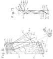
- Figures 16 to 23 show embodiments having a further improved laser beam utilization factor.
- a beam is propagated inside the stand (transparent light guide plate), and only a part of the scanning beam entering the stand is effectively used for reading bar codes. Namely, the utilization efficiency of the scanning beam is not always satisfactory.
- the laser beam P emitted from the laser source 41 is guided by the polygonal mirror 31 from A1 to B1, from A2 to B2, and from A3 to B3 (refer to Fig. 23(D)) to provide beams, which enter the lower part of the transparent stand portion 23, are propagated inside the transparent stand portion by repetitive total reflection, and made incident on the upper hologram windows H1, H2, and H3, respectively.
- Respective surfaces 31a, 31b, and 31c of the polygonal mirror 31 have different inclinations, so that the beam reflected by the respective surfaces provides beams indicated with reference marks Pa, Pb, and Pc in Fig. 13.
- the scanning beam Pa travels toward the hologram window H1, exits therefrom, and travels obliquely as indicated with a reference mark D1 (the scanning line a).
- the scanning beam Pc travels toward the hologram window H3, exits therefrom, and travels obliquely opposite to the direction D1 as indicated with a reference mark D3 (the scanning line c).
- the scanning beam Pb travels toward the hologram window H2, exits therefrom, and travels horizontally as indicated with a reference mark D2 (the scanning line b).
- the scanning line b is in parallel with the plane of the transparent light guide plate 23.
- the scanning width of a beam widens while the beam is propagated upward inside the transparent light guide plate 23.
- each of the vertical, horizontal, and oblique scanning patterns requires a one time scanning, so that, as apparent in Fig. 23, three scanning operations of Al to B1, A2 to B2, and A3 to B3 are needed. This means that the polygonal mirror 31 needs three surfaces, which lowers the performance of the scanner.
- a laser beam scanning line dividing means is arranged inside the transparent light guide plate 23. This dividing means deflects the laser beam portions usually not used toward the respective hologram emission windows, thereby improving the utilization efficiency of laser beam.
- the laser beam scanning line dividing means can form a set of vertical, horizontal, and oblique bar code reading patterns in a short time.
- Figure 16 shows an embodiment of a stand type scanner for a bar code reader, having the scanning line dividing means.
- a numeral 31 denotes a polygonal mirror, and 41 a laser source for repeatedly providing a laser beam P from (1) to (5).
- the polygonal mirror 31 has surfaces 31a, 31b, 31c, ... having an identical inclination to guide the laser beam P on the same locus from (1) to (5).
- Numeral 23 denotes a transparent light guide plate made of a transparent glass plate arranged upright. A lower part of the light guide plate agrees with the locus of the laser beam P.
- An upper part of the light guide plate 23 has four rows of emission hologram windows H1 to H4.
- Numerals 16-1 to 16-4 denote reflection type holograms arranged at the lower part of the light guide plate 23 along the locus of the laser beam to form the laser beam dividing means.
- the holograms 16-1 to 16-4 have different optical characteristics respectively.
- the hologram 16-1 deflects the laser beam P toward the hologram window H1 as indicated with a reference mark 17-1 (Fig. 18 (A)).
- the hologram 16-2 deflects the laser beam P toward the hologram window H2 as indicated with a reference mark 17-2 (Fig. 18 (B)).
- the hologram 16-3 deflects the laser beam P toward the hologram window H3 as indicated with a reference mark 17-3 (Fig. 18 (C)).
- the hologram 16-4 deflects the laser beam P toward the hologram window H4 as indicated with a reference mark 17-4 (Fig. 18 (D)).
- the hologram windows H1 to H4 have optical characteristics to vertically, horizontally, and obliquely diffract the laser beams 17-1 to 17-4 as indicated with reference marks 18-1 to 18-4 in Fig. 16.
- the hologram 16-1 diffracts the beam in the section from (1) to (2) to provide the laser beam 17-1, which repeats a total reflection in the light guide plate 23 and reaches the hologram window H1, which diffracts the laser beam to provide the scanning laser beam 18-1.
- the hologram 16-2 diffracts the beam to provide the laser beam 17-2, which is diffracted by the hologram window H2 to form the scanning beam 18-2.
- the hologram 16-3 diffracts the beam to provide the laser beam 17-3, which is diffracted by the hologram window H3 to form the scanning beam 18-3.
- the hologram 16-4 diffracts the beam to provide the laser beam 17-4, which is diffracted by the hologram window H4 to form the scanning beam 18-4.
- the beam is divided into the four laser beams 17-1 to 17-4, which become the laser beams 18-1 to 18-4 emitted from the respective hologram windows and used to read a bar code, thereby further improving the utilization efficiency of the laser beam P.
- a set of the vertical, horizontal, and oblique patterns 18-1 to 18-4 is formed by one scan of the laser beam P from (1) to (5) by a single surface of the polygonal mirror 31. This can shorten a time for forming the set of the patterns, to thereby improve the performance of the scanner.
- Figures 20 and 21 show another embodiment different from the one shown in Figs. 16 and 17
- parts corresponding to those of Figs. 16 and 17 are represented with like reference marks.
- a transparent light guide plate 23 has, on its lower surface, four divided reflection surfaces 21-1 to 21-4 having different inclinations.
- the reflection surfaces 21-1 to 21-4 reflect the laser beam, and the reflected beams are propagated, similar to the laser beams 17-1 to 17-4, inside the light guide plate 23 toward emission hologram windows Hl to H4.
- FIG. 22 shows still another embodiment.
- a transparent light guide plate 23 has, at its intermediate portion, four transmission type holograms 61-1 to 61-4 having different diffraction characteristics and arranged side by side in a scanning direction.
- a laser beam propagated from a lower part inside the light guide plate 23 sequentially scans the holograms 61-1 to 61-4, which diffract the laser beam in predetermined directions, thereby dividing the laser beam into four beams.
- the divided four laser beams are emitted from respective emission hologram windows H1 to H4.
- a single scanning laser beam provided by a laser beam scanning means is divided into a plurality of scanning laser beams, which are directed toward emission hologram windows for emitting the divided laser beams in different directions.
- This arrangement can improve the utilization efficiency of laser beam scanning lines when reading bar codes.
- the embodiments can form a set of vertical, horizontal, and oblique scanning patterns for reading bar codes in a short time, to thereby improve the performance of the bar code reader.
- Figures 24 to 29 show embodiments each having a common substrate incorporating a laser scanning portion, for emitting various scanning patterns from a light emission window 25 depending on the use.
- a bar code B on a commodity is easily read with orthogonal two scanning patterns.
- the two scanning patterns can perform a reading operation in any direction. If there is only one scanning line, the scanning line may not completely cross the bar code depending on the orientation of the commodity (bar code) handled by an operator, and the bar code may not be read. This problem becomes bigger as the bar code becomes smaller. For example, reading a short (truncate) symbol may require at least three to five multidirectionally crossing scanning patterns.
- Bar codes used in a physical distribution such as those based on Code 39, Interleaved 2 out of 5 have low information density and no limitation in the number of digits, and thus are extremely long laterally.
- the orthogonal patterns or the equiangular crossing patterns oriented in three to five directions are incapable of carrying out the multidirectional reading operation, and it is necessary to adjust an angle of the bar code when reading the same.
- a diffracted direction of an outgoing beam from a light emission window is uniquely determined by a hologram, so that the diffracted direction cannot be changed without changing (preparing again) the design of the hologram.
- Figures 24 and 25 show a basic arrangement of an embodiment of a laser scanner having an exchangeable transparent light guide plate 23.
- the transparent light guide plate 23 is removably fitted on a substrate 20.
- a hologram 27 for forming a scanning beam emission window 25 is arranged at an upper part of the transparent light guide plate 23.
- the hollow substrate 20 incorporates a scanning optical system having a polygonal mirror 31 rotated by a motor 35. According to the rotation, the polygonal mirror 31 guides a beam in a plane of the substrate 20.
- a scanning beam introducing hologram 38 formed at a lower end of the transparent light guide plate 23 diffracts the beam upward into the transparent light guide plate 23.
- the scanning beam inside the transparent light guide plate 23 repeats a total reflection, and as shown in the figures, is diffracted by and emitted from the emission window 25 (hologram 27) in a predetermined direction.
- An incident direction toward the transparent light guide plate 23 and an outgoing direction from the transparent light guide plate 23 are optionally set by properly designing pitches of interference fringes of the holograms 27 and 38.
- the substrate 20 has recesses 64 for removably receiving the transparent light guide plate 23.
- the recesses 64 are fixedly provided with guides 68 (Fig. 25) for easily fitting and removing the transparent light guide plate 23 in a sliding manner in a vertical direction.
- the guides 68 may be a pair of facing channel-shaped groove members as shown in the figure.
- a sealing window glass 66 for preventing water, dust etc., from entering the inside of the substrate 20 is arranged at a part of the substrate 20 facing the introducing hologram 38 of the transparent light guide plate 23.
- Figures 26 to 29 show several examples of the transparent light guide plate 23, having various holograms (emission portions) 27.
- Each of the examples has three holograms 27 (H1, H2, and H3) at an emission portion thereof to produce three scanning patterns.
- a scanning beam P from the polygonal mirror 31 is propagated upward and in parallel inside the transparent light guide plate 23 due to repetitive total reflection.
- the respective holograms H1, H2, and H3 receive the coherent scanning lines, and provide beams in respective diffraction directions (corresponding to scanning lines a, b, and c) as shown in Fig. 26.
- the middle hologram H2 for example, does not twist the scanning direction of the beam by diffraction and provides the scanning beam b that is in parallel with the incident scanning beam.
- the holograms H1 and H2 twist the incident beams by diffraction and provide the scanning lines a and c.
- the scanning lines a, b, and c form three scanning patterns crossing one another.
- the unidirectional scanning beam (coherent scanning beam) inside the transparent light guide plate 23 is converted by the holograms H1, H2, and H3 into the scanning patterns of three directions crossing one another.
- the number of the scanning lines may be infinitely increased in theory, by increasing the number of the holograms.
- the scanning beam P is coherently separated by slightly changing the reflection surfaces of the polygonal mirror 31, thereby easily forming the coherent incident scanning beams for the holograms H1, H2, and H3 respectively.
- This embodiment is suitable for reading UPC system bar codes.
- Figure 27 shows another embodiment.
- a transparent light guide plate 23A has holograms H1', H2', and H3' which produce scanning patterns a', b', and c' having smaller crossing angles than those shown in Fig. 28.
- This embodiment is suitable for, for example, a bar code having an extremely long lateral length (with short height) which cannot be read by the scanning patterns of Fig. 26.
- the patterns having the small crossing angles can extend margins for adjusting the angle of a bar code.
- Figure 28 shows a transparent light guide plate 23B having an emission portion 25 provided with a single hologram 27. in this case, a diffraction direction shifts in parallel depending on an incident position on the hologram 27, thereby forming separated parallel patterns.
- the embodiment of Fig. 28 can also extend a positioning margin when reading extremely wide codes such as those based on Code 39 or Interleaved 2 out of 5.
- the transparent light guide plates 23 (Fig. 26), 23A (Fig. 27), and 23B (Fig. 28) can be exchanged one for the other, depending on the conditions of the commodities and sales points, to provide required scanning patterns.
- Figure 29 shows an embodiment that can cope with the size of a commodity.
- This embodiment employs a transparent light guide plate 23C having holograms Ha, Hb, and Hc which have different focal lengths f1, f2, and f3, respectively, thereby substantially expanding the reading regions (depths).
- the transparent light guide plate 23 has the emission portion 25 formed of holograms.
- the light guide plate 23 (23A, 23B, 23C) having a light emission window of a specific purpose is removably fitted to the common substrate 20 to easily provide various scanning patterns without changing the scanning optical system.
- Embodiments of the present invention are applicable in POS systems employed in registers in supermarkets, department stores, and other speciality stores.
Landscapes
- Physics & Mathematics (AREA)
- Engineering & Computer Science (AREA)
- Electromagnetism (AREA)
- Artificial Intelligence (AREA)
- Toxicology (AREA)
- General Health & Medical Sciences (AREA)
- Health & Medical Sciences (AREA)
- Computer Vision & Pattern Recognition (AREA)
- General Physics & Mathematics (AREA)
- Theoretical Computer Science (AREA)
- Mechanical Optical Scanning Systems (AREA)
- Holo Graphy (AREA)
- Character Input (AREA)
Abstract
Description
- The present invention relates to bar code reading apparatus.
- Laser scanners are extensively used in point-of-sale (POS) systems at supermarkets, department stores, and other speciality stores for reading bar codes. These stores usually use a stand-type laser scanner, as it is relatively small and occupies little space.
- Namely, the stand-type laser scanner is compact and takes up little space, and thus is suitable for a small store having only a small space for a check-out counter.
- As shown in Figs. 30 and 31, a conventional stand-type scanner has a scanning optical system incorporated in a
support unit 5 protruding from a substrate (a base plate) 6 arranged on acounter 9. This arrangement usually increases the size of the support unit, and accordingly the size of the scanner as a whole, and spoils the appearance thereof. Since the arrangement is made mainly from the viewpoint of an easy observation by an operator A, asupport 7 blocks the sight of a customer B, who therefore cannot clearly see abar code 10 on a commodity 8. Namely, the conventional stand-type laser scanner is not transparent and is located between the customer and the operator, and thus the customer cannot see or read the bar code on the commodity through the stand-type laser scanner and must shift his or her position to see the bar code. In the figures, P denotes a scanning beam emitted in the direction of an arrow mark. - Another conventional bar code reading apparatus for reading a bar code on an object, disclosed in JP-A-62-243081, may be considered to comprise: a laser source for emitting a laser beam; laser beam scanning means for deriving from the emitted laser beam a scanning beam which passes out of the apparatus, via a light emission window, towards the object and scans in a predetermined scanning pattern across the bar code on the object; and optical detecting means for detecting light reflected back towards the apparatus from the bar code; the said laser beam scanning means and the said optical detecting means both being incorporated in a base unit of the apparatus, and the said light emission window being supported on the base unit by a support member.
- In this apparatus the scanning optical system is incorporated in the base unit, rather than being in the external support unit above the base unit as in Figs. 30 and 31. However, the support member still blocks the customer's view of the bar code.
- Figure 32 shows a typical check-out counter according to another prior art. Generally, there are three (indicated by (1), (2), and (3)) commodity price display portions (displays) arranged on a
keyboard 2 above a barcode reading portion 4 and on aPOS register portion 3. - It is impossible for a customer, however, to simultaneously observe any one of the displays and a bar code of a commodity (which is passed over the reading portion 4) handled by an operator. Namely, if the customer wishes to confirm the bar code reading operation as well as the displayed price, the customer must shift his or her position alternately to see them.
- According to the present invention there is provided a bar code reading apparatus as defined in
claim 1. - Such bar code reading apparatus has a reduced size and can enable a customer to easily observe the bar code reading operation. Because the support member is transparent, it does not spoil the appearance of the apparatus. In addition, the support member external to the base unit does not incorporate the scanning optical system, and thus the support member is compact. A customer can easily observe and confirm a bar code operation through the transparent support member.
- Incidentally, EP-A-0194115 discloses a hand-held bar code reading apparatus in which the outgoing and incoming light can pass through a transparent housing portion.
- It is preferable to integrally incorporate the laser source in the base unit.
- The transparent support member may be a light guide plate in which the outgoing light and returning signal light repeat a total reflection and are propagated in the light guide plate.
- It is preferable to form one or a plurality of holograms on the light emission window, to diffract the laser beam in one or more predetermined directions toward the bar code.
- When the light emission window is provided with one or more holograms the diffracting direction(s) of the scanning beam(s) can be selected readily, and by controlling the scanning direction(s) in this way the bar code can be easily read.
- The laser beam scanning means may be either a galvanomirror or a rotatable polygonal mirror.
- In one embodiment of the invention, the apparatus further comprises a reflection-type hologram provided on the said support member to reflect, in a predetermined direction, only a specific wavelength of light, and an indicator, located on the side of the support member that is opposite the side on which the said light emission window is located, for displaying information; the indicator producing light having a wavelength substantially identical to the said specific wavelength, so that such light from the indicator is reflected by the said reflection-type hologram and appears, to a viewer positioned on the same side of the said support member as the indicator, to have originated from a position close to the bar code.
- The wavelength of the laser beam preferably differs from that of the light produced by the indicator.
- Preferably, the support member is removably fitted to the base unit.
- According to still another embodiment of the invention, there is provided a laser beam dividing means for dividing an outgoing laser beam from the laser source into a plurality of laser beams that are made incident on respective holograms of the light emission window. The laser beam dividing means is preferably composed of a plurality of reflection type holograms.
- The laser source may be a semiconductor laser.
- Reference will now be made, by way of example, to the accompanying drawings, in which;
- Fig. 1 is a perspective view showing a basic arrangement of bar code reading apparatus embodying the present invention;
- Fig. 2 is a schematic side view of the Fig. 1 arrangement;
- Fig. 3 is a partial view showing a modification to a portion (scanning beam outgoing portion) of the Fig. 1 apparatus;
- Fig. 4 is a partial view showing a modification to a different portion (scanning beam incident portion) of the Fig. 1 apparatus;
- Fig. 5 is a view showing an alternative modification to that of Fig. 4;
- Fig. 6 is a plan view for use in explaining a scanning optical system for reading bar codes used in an embodiment of the present invention;
- Fig. 7 is a partial view showing a modification to Fig. 6 system;
- Fig. 8 is a perspective view for use in explaining operation of the Fig. 1 apparatus;
- Fig. 9 is a perspective view showing a basic arrangement of bar code reading apparatus (stand-type laser scanner) according to another embodiment of the present invention;
- Fig. 10 is a general view schematically showing a check-out counter for use in explaining operation of the embodiment of Fig. 9;
- Fig. 11 is an enlarged view of a reflection type hologram shown in Fig. 10;
- Fig. 12 is a perspective view showing a principle of bar code reading apparatus according to still another embodiment of the present invention;
- Fig. 13 is a schematic side view of the Fig. 12 arrangement;
- Figs. 14A and 14B are views showing respectively a method of preparing an optical component of the Fig. 12 embodiment used to produce an untwisted scanning line and a method of recreating that line using the finished component;
- Figs. 15A and 15B are views corresponding respectively to Figs. 14A and 14B but relating to a twisted scanning line;
- Fig. 16 is a view showing bar code reading apparatus (stand-type scanner) according to still another embodiment of the present invention;
- Fig. 17 is a view explaining the division and propagation of a laser beam in the Fig. 16 apparatus;
- Fig. 18 is a view showing the propagation within the apparatus of each divided laser beam in Fig. 17;
- Fig. 19 is a view for use in explaining a utilization factor of a laser beam and a formation of a scanning pattern;
- Fig. 20 is a schematic side view showing parts of another bar code reading apparatus embodying the present invention;
- Fig. 21 is a perspective view showing a lower region of the parts shown in Fig. 20;
- Fig. 22 is a schematic view showing parts of another bar code reading apparatus embodying the present invention;
- Fig. 23 is a view for use in explaining a utilization factor of a beam and a formation of a scanning pattern in the apparatus of Fig. 12;
- Fig. 24 is a schematic side view showing a basic arrangement of a bar code reading apparatus according to another embodiment of the invention;
- Fig. 25 is an enlarged perspective view of Fig. 24;
- Figs. 26 to 29 are views showing four examples of exchangeable light guide plates for realising various scanning line patterns;
- Fig. 30 is a perspective view showing an example of a prior art bar code reading apparatus (stand-type laser scanner);
- Fig. 31 is a view showing a check-out counter employing the Fig. 30 stand-type laser scanner and
- Fig. 32 is a general view schematically showing another example of a prior art check-out counter.
- Figures 1 and 2 show a basic arrangement of a stand type laser scanner according to an embodiment of the present invention. In the figures, a transparent light guide plate (support member) 23 is integrally formed on a substrate (base unit) 20, and a scanning
beam emission window 25 is formed at an upper part of the light guide plate. According to the embodiment shown, theemission window 25 is formed from ahologram 27. The transparentlight guide plate 23 serves to support theemission window 25. When the scanner is particularly intended to be used at a register counter of a supermarket, etc., the upper part of the light guide plate may be curved to this side (the side of the operator) as shown in the figures, so that a scanning beam P always irradiates a bar code (B in Fig. 34) of a commodity 8. As shown in Fig. 2, thesubstrate 20 incorporates a scanning optical system for the scanning beam P. This scanning optical system has, for example, a polygonal mirror (rotatable polygonal mirror) 31 known per se rotated around arotary shaft 33 by amotor 35. In response to the rotation, thepolygonal mirror 31 guides the beam P in a plane of thesubstrate 20 so that the beam is reflected upward from alower mirror 37a into the transparentlight guide plate 23. The scanning beam repeats a total reflection inside the transparentlight guide plate 23, and as shown in the figures, is diffracted by thehologram 27 in a predetermined direction and emitted from theemission window 25. The emitting direction is optionally set according to the design of a pitch of interference fringes, etc., of thehologram 27. A light source of the scanning beam P is, for example, a semiconductor laser 41 (Fig. 2). The beam is made incident on thepolygonal mirror 31 from, for example, the inside of thesubstrate 20. - This embodiment is characterized in that the
light guide plate 23 forming the support of theemission window 25 is transparent, and that optical systems (the scanning optical system, etc.,) except for theemission window 25 are integrally incorporated inside thesubstrate 20. - Figure 3 shows another embodiment of the invention. In the figure, a
reflection mirror 37b is fitted to an upper part of the transparentlight guide plate 23, and thereflection mirror 37b reflects the scanning beam P out through theemission window 25. In this case, thehologram 27 is not needed at theemission window 25. Thereflection mirror 37b is fixed to the upper end (opposite to the commodity) of the transparentlight guide plate 23 by adhesion or vapor deposition. - Figure 4 shows still another embodiment of the invention. In the figure, a
lower end face 23a of the transparentlight guide 23 is obliquely cut. Without thelower reflection mirror 37a of Fig. 2, thelower end face 23a directly entirely reflects a scanning beam upward into the transparentlight guide plate 23. - As shown in Fig. 5, a
hologram 38 may be arranged at a lower end portion of the transparentlight guide 23. Thehologram 38 diffracts the scanning beam P from the polygonal mirror 31 (Fig. 2) in a predetermined direction to guide the beam upward into the transparentlight guide plate 23. - Figure 6 shows a laser beam scanning and signal light collecting optical system according to an embodiment of the present invention. In the figure, a laser source 41 (an He-Ne laser or a semiconductor laser) emits a light beam, which is converted by a
beam shaping lens 43 into a beam having a predetermined diameter and shape. The beam enters thepolygonal mirror 31, and due to the rotation of thepolygonal mirror 31 around theshaft 33, the beam becomes the scanning beam P which enters the transparentlight guide plate 23. The beam P traces the scanning beam path mentioned before. The beam scanning the bar code B (Fig. 34) of the commodity 8 is accordingly scattered, and part of the scattered light again enters, as signal light S, the transparentlight guide plate 23. The signal light S traces the same path as before and returns to thepolygonal mirror 31. The signal light S is then reflected by thepolygonal mirror 31 and by a holedconcave mirror 49, and guided to aphotodetector 51. The processes carried out after the detection of the signal light by thephotodetector 51 are not the object of the invention and are well known, and therefore, a detailed explanation thereof is omitted. The size and position of a pinhole 49a of the holedconcave mirror 49 are set so as not to interfere with a beam traveling toward thepolygonal mirror 31. - As is known, instead of the
polygonal mirror 31 it is possible to use agalvanomirror 30 of Fig. 7. - In the above embodiment, the scanning optical system is incorporated in the
substrate 20 but not disposed inside the transparentlight guide plate 23, and thus the transparentlight guide 23 may have a compact design. In addition, as shown in Fig. 8, a customer can easily observe a reading operation of the bar code B from the back of and through the transparentlight guide plate 23. - The light source need not be incorporated inside the
substrate 20 but can be located outside the substrate, and an outgoing beam from the outside light source guided into the substrate. - Figures 9 to 11 show an embodiment which enables a customer to observe a bar code B of a commodity as well as a price display.
- As explained before, the scanning optical system (such as the
polygonal mirror 31 andmirror 37a) incorporated inside thesubstrate 20 provides a scanning beam, which is propagated inside thelight guide plate 23 in parallel and externally emitted from theemission window 25 in a predetermined direction. Since the support portion is transparent, a customer can observe a bar code but cannot simultaneously observe a price display. This is because the price display is usually oriented toward an operator, and thus cannot be seen by the customer. According to the embodiment of Figs. 9 to 11, a display (an indicator) 53 is arranged on thesubstrate 20 and oriented toward the operator, but information displayed on the display can be seen by a customer positioned behind the display. - Figures 9, 10, and 11 show a basic arrangement of the stand type laser scanner according to the embodiment of the invention. In the figures, a transparent
light guide 23 is fitted on asubstrate 20. A scanningbeam emission window 25 composed of ahologram 27 is fitted to an upper part of the light guide plate. Thesubstrate 20 incorporates a scanning optical system having apolygonal mirror 31 rotated by a motor 35 (Fig. 2). In response to the rotation, thepolygonal mirror 31 guides a beam in a plane of thesubstrate 20. The beam is guided by areflection mirror 37a (Fig. 2) upward into the transparentlight guide plate 23. The scanning beam inside the transparentlight guide plate 23 repeats a total reflection, and as shown in the figures, is diffracted by and emitted from the emission window (hologram) 25 in a predetermined direction to irradiate a bar code. These arrangements are the same as those of the embodiment shown in Figs. 1 to 8. - According to this embodiment, a
reflection type hologram 42 is formed at the back thereof, i.e., the customer's side opposite to theemission window 25. A price indicator (display) 53 is integrally obliquely arranged on thesubstrate 20 on the same side as thereflection type hologram 42, to face thereflection type hologram 42 of the transparentlight guide plate 23. - As is known, the reflection type hologram has diffraction characteristics of reflecting light having a specific wavelength, and the diffraction characteristics can be optionally controlled by properly designing a pitch of the hologram (interference fringes), etc.
- According to the check-out counter of the above-mentioned arrangement, information light L (Fig. 10) from the
price indicator 53 is reflected and diffracted by thereflection type hologram 42 in a predetermined direction, to be able to be seen by a customer. As a result, the customer can see a virtual image of a price (Yen 123 in the figure) on theindicator 53 as well as a bar code B on a commodity handled by the operator. This principle is the same as the principle of a headup display that overlays information light (corresponding to the price information) over a background (corresponding to the bar code of the commodity). - The color of the information light L of the
indicator 53 preferably matches the color, for example, green, of light (having the particular wavelength) reflected from thereflection type hologram 42. - As shown in Fig.11, the scanning beam P propagated in the transparent
light guide plate 23 also enters thereflection type hologram 42 for the indicator. If the wavelength of the scanning beam P is selected to be different (for example, red) from the selected wavelength of thereflection type hologram 42, it will not be affected by thereflection type hologram 42. Namely, as if thereflection type hologram 42 were omitted, the scanning beam is propagated upward by a repetitive total reflection in the transparentlight guide plate 23. - The
hologram 42 may be formed at either side of the light guide plate. - As explained above, the price information light L from the
indicator 53 is reflected and diffracted by thereflection type hologram 42 in a predetermined direction, so that a virtual image of the information substantially overlaps a bar code of a commodity positioned behind the transparentlight guide plate 23. Namely, as in the headup display, a customer can observe the bar code as well as the price information light, one upon the other, without shifting position. - Figures 12 to 17B show embodiments which read a bar code B by using a plurality of crossing scanning line patterns.
- To clearly read a bar code on a commodity in a POS system, it is preferable to use scanning line patterns that cross and are oriented in at least two directions. If only one scanning line is used, the scanning line may not impinge on the bar code, depending on the orientation of the commodity (bar code) handled by an operator, and as a result, the bar code cannot be read. This frequently happens when the bar code is small. For a very small bar code, at least three to five multidirectional crossing patterns are needed.
- The embodiments shown in Figs. 1 to 11 basically employ a single (unidirectional) scanning line.
- Figures 12 and 13 show an embodiment of a stand type laser scanner employing multiple scanning lines. In the figures, a transparent
light guide plate 23 is integrally formed on a substrate 20 (Fig. 13), and a scanningbeam emission window 25 is formed at an upper part of the light guide plate. Theemission window 25 has a plurality of holograms H1, H2, and H3 arranged vertically on a substantially vertical plane. Thesubstrate 20 incorporates a scanning optical system having apolygonal mirror 31 rotated by amotor 35. In response to the rotation, thepolygonal mirror 31 guides a beam in a plane of thesubstrate 20. The beam is guided upward by alower end face 23a of the transparentlight guide plate 23 into the guide plate. The scanning beam in the transparentlight guide plate 23 repeats a total reflection, and as shown in the figures, is diffracted by and emitted from theemission window 25 in predetermined directions. The emission directions can be set by properly designing the pitches of interference fringes of the holograms H1, H2, and H3. In Fig. 12, numeral 41 denotes a semiconductor laser serving as a light source. - The scanning beam from the
polygonal mirror 31 is propagated upward in the transparentlight guide plate 23 due to the repetitive total reflection. The holograms H1, H2, and H3 receive the coherent scanning beam and emit beams in respective diffraction directions D1, D2, and D3 as shown in Fig. 13. In Fig. 12, the middle hologram H2, for example, does not turn (twist) the scanning direction by diffraction but provides a scanning beam b that is in parallel with the incident scanning beam P. On the other hand, the holograms H1 and H3 provide twisted scanning lines a and c due to the diffraction, Namely, the scanning lines a, b, and c form three scanning line patterns crossing one another. Note, the unidirectional scan (parallel scan) in the transparentlight guide plate 23 is converted by the holograms H1, H2, and H3 into the scanning patterns of three directions crossing one another. Just after the holograms, the scanning lines a and c are not twisted sufficiently and substantially in parallel with each other. A bar code reading operation with the stand type scanner is usually carried out, however, by putting a bar code (a commodity) on a table so that a region to be read is close to the surface of the table which is spaced from the holograms by a certain distance. The cross pattern scanning method of the invention, therefore, raises no problems in practical use. As mentioned before, the number of scanning lines can be increased infinitely in theory, by increasing the number of holograms, to thereby realize an all-round reading. - The angles of the reflection surfaces 31a, 31b, ..., 31i of the
polygonal mirror 31 may be made slightly different from one another, to separate a scanning beam in parallel so that coherent incident scanning beams for the respective holograms are easily formed as shown in Fig. 13. - Figures 14A and 14B schematically show the way of forming the hologram H2 that produces the untwisted scanning line b, and recreating the line b. First, in a forming system, a hologram
dry plate 70 is irradiated with two spherical waves (reference light and object light) coming in the direction of an axis y (in a plane of the hologram dry plate). Interference exposure by the waves forms the hologram H2. When a recreation beam Lr is emitted from a spot light source of the reference light, which is one of the holograms forming light, toward the hologram H2, the untwisted diffraction beam b is recreated (Fig. 14B). - Figures 15A and 15B show optical systems for forming and recreating the twisted scanning lines a and c. As shown in Fig. 15A the spot light source for the forming waves is simply shifted in a direction x in a forming process of a hologram. When the recreation beam Lr is made incident on the hologram in the direction y similar to Fig. 14B the diffraction light is twisted to provide the twisted scanning line c (or a) as shown in Fig. 15B. Alternatively, as is well known, wavelengths of the forming waves and recreation wave may be made different from one other to cause a chromatic aberration with which the twisted scanning lines are formed.
- According to the embodiment mentioned above, a plurality of holograms are employed in a simple and compact structure to form multidirectional scanning line patterns which can improve the quality of a bar code reading operation.
- Namely, a scanning beam from the scanning optical system incorporated in the substrate is propagated in parallel with the light guide plate and externally emitted from the emission portion in predetermined directions. At this time, a plurality of the holograms arranged at the emission portion diffract respective scanning beams in directions determined by the respective holograms, thereby easily crossing the scanning lines with one another. The number of the scanning lines can be easily increased by increasing the number of the holograms arranged at the emission portion, thereby realizing, without an increase of the overall size, a laser scanner that reads bar codes without error.
- Figures 16 to 23 show embodiments having a further improved laser beam utilization factor.
- According to the above embodiments employing the transparent light guide plate, a beam is propagated inside the stand (transparent light guide plate), and only a part of the scanning beam entering the stand is effectively used for reading bar codes. Namely, the utilization efficiency of the scanning beam is not always satisfactory.
- For example, in the embodiment shown in Figs. 12 and 13, the laser beam P emitted from the
laser source 41 is guided by thepolygonal mirror 31 from A1 to B1, from A2 to B2, and from A3 to B3 (refer to Fig. 23(D)) to provide beams, which enter the lower part of thetransparent stand portion 23, are propagated inside the transparent stand portion by repetitive total reflection, and made incident on the upper hologram windows H1, H2, and H3, respectively. -
Respective surfaces polygonal mirror 31 have different inclinations, so that the beam reflected by the respective surfaces provides beams indicated with reference marks Pa, Pb, and Pc in Fig. 13. - The scanning beam Pa travels toward the hologram window H1, exits therefrom, and travels obliquely as indicated with a reference mark D1 (the scanning line a).
- The scanning beam Pc travels toward the hologram window H3, exits therefrom, and travels obliquely opposite to the direction D1 as indicated with a reference mark D3 (the scanning line c).
- The scanning beam Pb travels toward the hologram window H2, exits therefrom, and travels horizontally as indicated with a reference mark D2 (the scanning line b). The scanning line b is in parallel with the plane of the transparent
light guide plate 23. - According to the rotation of the
polygonal mirror 31, the above operation is repeated to read a bar code. - As shown in Fig. 12, the scanning width of a beam widens while the beam is propagated upward inside the transparent
light guide plate 23. - Accordingly, among the scanning width A1-B1 at the incident portion of the transparent
light guide plate 23, only a central part indicated with C-D is used for reading a bar code (refer to Fig. 23). Namely, the utilization efficiency of the beam is poor. Namely, a scanning line of the small width C-D is widened to the full width of the window (the width of the hologram). - In addition, each of the vertical, horizontal, and oblique scanning patterns requires a one time scanning, so that, as apparent in Fig. 23, three scanning operations of Al to B1, A2 to B2, and A3 to B3 are needed. This means that the
polygonal mirror 31 needs three surfaces, which lowers the performance of the scanner. - To improve the utilization efficiency of laser beam, a laser beam scanning line dividing means is arranged inside the transparent
light guide plate 23. This dividing means deflects the laser beam portions usually not used toward the respective hologram emission windows, thereby improving the utilization efficiency of laser beam. - The laser beam scanning line dividing means can form a set of vertical, horizontal, and oblique bar code reading patterns in a short time.
- Figure 16 shows an embodiment of a stand type scanner for a bar code reader, having the scanning line dividing means.
- A numeral 31 denotes a polygonal mirror, and 41 a laser source for repeatedly providing a laser beam P from (1) to (5).
- The
polygonal mirror 31 hassurfaces -
Numeral 23 denotes a transparent light guide plate made of a transparent glass plate arranged upright. A lower part of the light guide plate agrees with the locus of the laser beam P. - An upper part of the
light guide plate 23 has four rows of emission hologram windows H1 to H4. - Numerals 16-1 to 16-4 denote reflection type holograms arranged at the lower part of the
light guide plate 23 along the locus of the laser beam to form the laser beam dividing means. - The holograms 16-1 to 16-4 have different optical characteristics respectively. The hologram 16-1 deflects the laser beam P toward the hologram window H1 as indicated with a reference mark 17-1 (Fig. 18 (A)).
- The hologram 16-2 deflects the laser beam P toward the hologram window H2 as indicated with a reference mark 17-2 (Fig. 18 (B)).
- The hologram 16-3 deflects the laser beam P toward the hologram window H3 as indicated with a reference mark 17-3 (Fig. 18 (C)).
- The hologram 16-4 deflects the laser beam P toward the hologram window H4 as indicated with a reference mark 17-4 (Fig. 18 (D)).
- The hologram windows H1 to H4 have optical characteristics to vertically, horizontally, and obliquely diffract the laser beams 17-1 to 17-4 as indicated with reference marks 18-1 to 18-4 in Fig. 16.
- As shown in Fig. 19, when the laser beam P is once guided at the lower part of the
light guide plate 23 from (1) to (5), the hologram 16-1 diffracts the beam in the section from (1) to (2) to provide the laser beam 17-1, which repeats a total reflection in thelight guide plate 23 and reaches the hologram window H1, which diffracts the laser beam to provide the scanning laser beam 18-1. - In the section from (2) to (3), the hologram 16-2 diffracts the beam to provide the laser beam 17-2, which is diffracted by the hologram window H2 to form the scanning beam 18-2.
- In the section from (3) to (4), the hologram 16-3 diffracts the beam to provide the laser beam 17-3, which is diffracted by the hologram window H3 to form the scanning beam 18-3.
- In the section from (4) to (5), the hologram 16-4 diffracts the beam to provide the laser beam 17-4, which is diffracted by the hologram window H4 to form the scanning beam 18-4.
- As apparent from the above, when the laser beam P travels from (1) to (5), the beam is divided into the four laser beams 17-1 to 17-4, which become the laser beams 18-1 to 18-4 emitted from the respective hologram windows and used to read a bar code, thereby further improving the utilization efficiency of the laser beam P.
- A set of the vertical, horizontal, and oblique patterns 18-1 to 18-4 is formed by one scan of the laser beam P from (1) to (5) by a single surface of the
polygonal mirror 31. This can shorten a time for forming the set of the patterns, to thereby improve the performance of the scanner. - Figures 20 and 21 show another embodiment different from the one shown in Figs. 16 and 17 In the figures, parts corresponding to those of Figs. 16 and 17 are represented with like reference marks.
- A transparent
light guide plate 23 has, on its lower surface, four divided reflection surfaces 21-1 to 21-4 having different inclinations. - While a laser beam P is being moved from (1) to (5), the reflection surfaces 21-1 to 21-4 reflect the laser beam, and the reflected beams are propagated, similar to the laser beams 17-1 to 17-4, inside the
light guide plate 23 toward emission hologram windows Hl to H4. - Figure 22 shows still another embodiment.
- A transparent
light guide plate 23 has, at its intermediate portion, four transmission type holograms 61-1 to 61-4 having different diffraction characteristics and arranged side by side in a scanning direction. - A laser beam propagated from a lower part inside the
light guide plate 23 sequentially scans the holograms 61-1 to 61-4, which diffract the laser beam in predetermined directions, thereby dividing the laser beam into four beams. The divided four laser beams are emitted from respective emission hologram windows H1 to H4. - As explained above, according to the embodiments shown in Figs. 16 to 22 a single scanning laser beam provided by a laser beam scanning means is divided into a plurality of scanning laser beams, which are directed toward emission hologram windows for emitting the divided laser beams in different directions. This arrangement can improve the utilization efficiency of laser beam scanning lines when reading bar codes.
- Namely, the embodiments can form a set of vertical, horizontal, and oblique scanning patterns for reading bar codes in a short time, to thereby improve the performance of the bar code reader.
- Figures 24 to 29 show embodiments each having a common substrate incorporating a laser scanning portion, for emitting various scanning patterns from a
light emission window 25 depending on the use. - For symbols (bar codes) of standard size according to UPC/EAN/JAN codes in a POS system, a bar code B on a commodity is easily read with orthogonal two scanning patterns. The two scanning patterns can perform a reading operation in any direction. If there is only one scanning line, the scanning line may not completely cross the bar code depending on the orientation of the commodity (bar code) handled by an operator, and the bar code may not be read. This problem becomes bigger as the bar code becomes smaller. For example, reading a short (truncate) symbol may require at least three to five multidirectionally crossing scanning patterns.
- Bar codes used in a physical distribution such as those based on Code 39,
Interleaved 2 out of 5 have low information density and no limitation in the number of digits, and thus are extremely long laterally. For this kind of bar code, the orthogonal patterns or the equiangular crossing patterns oriented in three to five directions are incapable of carrying out the multidirectional reading operation, and it is necessary to adjust an angle of the bar code when reading the same. - In this way, it is generally necessary to change scanning patterns from one to another, depending on the use and location.
- The embodiments shown in Figs. 24 to 29 can satisfy such requirements. A diffracted direction of an outgoing beam from a light emission window is uniquely determined by a hologram, so that the diffracted direction cannot be changed without changing (preparing again) the design of the hologram.
- Figures 24 and 25 show a basic arrangement of an embodiment of a laser scanner having an exchangeable transparent
light guide plate 23. In the figures, the transparentlight guide plate 23 is removably fitted on asubstrate 20. Ahologram 27 for forming a scanningbeam emission window 25 is arranged at an upper part of the transparentlight guide plate 23. Thehollow substrate 20 incorporates a scanning optical system having apolygonal mirror 31 rotated by amotor 35. According to the rotation, thepolygonal mirror 31 guides a beam in a plane of thesubstrate 20. A scanningbeam introducing hologram 38 formed at a lower end of the transparentlight guide plate 23 diffracts the beam upward into the transparentlight guide plate 23. The scanning beam inside the transparentlight guide plate 23 repeats a total reflection, and as shown in the figures, is diffracted by and emitted from the emission window 25 (hologram 27) in a predetermined direction. An incident direction toward the transparentlight guide plate 23 and an outgoing direction from the transparentlight guide plate 23 are optionally set by properly designing pitches of interference fringes of theholograms substrate 20 hasrecesses 64 for removably receiving the transparentlight guide plate 23. Therecesses 64 are fixedly provided with guides 68 (Fig. 25) for easily fitting and removing the transparentlight guide plate 23 in a sliding manner in a vertical direction. Theguides 68 may be a pair of facing channel-shaped groove members as shown in the figure. - A sealing
window glass 66 for preventing water, dust etc., from entering the inside of thesubstrate 20 is arranged at a part of thesubstrate 20 facing the introducinghologram 38 of the transparentlight guide plate 23. - Figures 26 to 29 show several examples of the transparent
light guide plate 23, having various holograms (emission portions) 27. Each of the examples has three holograms 27 (H1, H2, and H3) at an emission portion thereof to produce three scanning patterns. - A scanning beam P from the
polygonal mirror 31 is propagated upward and in parallel inside the transparentlight guide plate 23 due to repetitive total reflection. The respective holograms H1, H2, and H3 receive the coherent scanning lines, and provide beams in respective diffraction directions (corresponding to scanning lines a, b, and c) as shown in Fig. 26. Here, as shown in Fig. 26, the middle hologram H2, for example, does not twist the scanning direction of the beam by diffraction and provides the scanning beam b that is in parallel with the incident scanning beam. On the other hand, the holograms H1 and H2 twist the incident beams by diffraction and provide the scanning lines a and c. Namely, the scanning lines a, b, and c form three scanning patterns crossing one another. In this way, the unidirectional scanning beam (coherent scanning beam) inside the transparentlight guide plate 23 is converted by the holograms H1, H2, and H3 into the scanning patterns of three directions crossing one another. The number of the scanning lines may be infinitely increased in theory, by increasing the number of the holograms. - The scanning beam P is coherently separated by slightly changing the reflection surfaces of the
polygonal mirror 31, thereby easily forming the coherent incident scanning beams for the holograms H1, H2, and H3 respectively. This embodiment is suitable for reading UPC system bar codes. - Figure 27 shows another embodiment. In the figure, a transparent
light guide plate 23A has holograms H1', H2', and H3' which produce scanning patterns a', b', and c' having smaller crossing angles than those shown in Fig. 28. This embodiment is suitable for, for example, a bar code having an extremely long lateral length (with short height) which cannot be read by the scanning patterns of Fig. 26. The patterns having the small crossing angles can extend margins for adjusting the angle of a bar code. - Figure 28 shows a transparent
light guide plate 23B having anemission portion 25 provided with asingle hologram 27. in this case, a diffraction direction shifts in parallel depending on an incident position on thehologram 27, thereby forming separated parallel patterns. The embodiment of Fig. 28 can also extend a positioning margin when reading extremely wide codes such as those based on Code 39 orInterleaved 2 out of 5. - As explained above, the transparent light guide plates 23 (Fig. 26), 23A (Fig. 27), and 23B (Fig. 28) can be exchanged one for the other, depending on the conditions of the commodities and sales points, to provide required scanning patterns.
- Figure 29 shows an embodiment that can cope with the size of a commodity. This embodiment employs a transparent light guide plate 23C having holograms Ha, Hb, and Hc which have different focal lengths f1, f2, and f3, respectively, thereby substantially expanding the reading regions (depths).
- In each of the above embodiments, the transparent
light guide plate 23 has theemission portion 25 formed of holograms. - As explained above, according to the embodiments of Figs. 24 to 29, the light guide plate 23 (23A, 23B, 23C) having a light emission window of a specific purpose is removably fitted to the
common substrate 20 to easily provide various scanning patterns without changing the scanning optical system. - Embodiments of the present invention are applicable in POS systems employed in registers in supermarkets, department stores, and other speciality stores.
Claims (33)
- Bar code reading apparatus, for reading a bar code on an object, comprising:a laser source (41) for emitting a laser beam;laser beam scanning means (31; 30) for deriving from the emitted laser beam a scanning beam (P) which passes out of the apparatus, via a light emission window (25), towards the object and scans in a predetermined scanning pattern across the bar code on the object; andoptical detecting means (49, 51) for detecting light reflected back towards the apparatus from the bar code;the said laser beam scanning means and the said optical detecting means both being incorporated in a base unit (20) of the apparatus, and the said light emission window being supported on the base unit by a support member (23);characterised in that the said support member (23) is transparent and serves as a light guide through which the said scanning beam and the reflected light are propagated.
- Apparatus as claimed in claim 1, wherein the said laser source (41) is also located in the said base unit (20).
- Apparatus as claimed in claim 1 or 2, wherein the said support member (23) is plate-like.
- Apparatus as claimed in any preceding claim, wherein the said light emission window (25) is formed at an upper end of the said support member (23).
- Apparatus as claimed in any preceding claim, wherein the said light emission window (25) has a hologram (27) provided thereon for diffracting the said scanning beam (P) so that it passes out of the apparatus in a predetermined direction.
- Apparatus as claimed in claim 5, wherein the said light emission window (25) has a plurality of holograms (H₁, H₂, H₃) which diffract the said scanning beam in different respective predetermined directions (D₁, D₂, D₃) towards the bar code.
- Apparatus as claimed in claim 6, wherein the holograms (H₁, H₂, H₃) of the said plurality have different diffraction properties and serve to produce a plurality of scanning beams which trace out intersecting scanning lines (a, b, c) on the object.
- Apparatus as claimed in claim 6 or 7, wherein the said holograms have different focal lengths.
- Apparatus as claimed in claim 6, 7 or 8, wherein the scanning line (b) traced out on the object by the scanning beam diffracted by at least one of the holograms (H₂) is substantially parallel to the direction in which the laser beam scans across the hologram concerned, and the scanning lines (a,c) traced out on the object by the scanning beams diffracted by other holograms (H₁, H₃) are each non-parallel with the direction in which the laser beam scans across the hologram concerned.
- Apparatus as claimed in claim 9, wherein the said laser beam scanning means comprise a rotatable polygonal mirror (31) having differently-inclined reflection surfaces (31a, 31b, 31c) for reflecting and dividing the laser beam emitted by the said laser source into a plurality of scanning beams directed respectively towards the associated holograms.
- Apparatus as claimed in claim 9, further comprising laser beam dividing means (16-1,...,16-4) for dividing the scanning beam produced by the laser beam scanning means (31) into a plurality of scanning beams (17-1,...,17-4) to be made incident respectively upon the associated holograms (H₁,...,H₄) of the said light emission window.
- Apparatus as claimed in claim 11, wherein the said laser beam dividing means comprise a plurality of dividing holograms provided on the said support member.
- Apparatus as claimed in claim 12, wherein the said dividing holograms are reflection-type holograms.
- Apparatus as claimed in claim 12 or 13, wherein the said dividing holograms (16-1,...,16-4) are aligned along a line, and the said laser beam scanning means (31) are such that the scanning beam produced thereby scans along that line when the apparatus is in use.
- Apparatus as claimed in claim 14, wherein the said reflection-type holograms (16-1,...,16-4) have different refraction characteristics such that the scanning beams produced respectively by those holograms are diffracted into the transparent support (23), in different respective directions, toward respective holograms (H₁,...,H₄) provided at the light emission window.
- Apparatus as claimed in claim 11, wherein the said laser beam dividing means comprise a plurality of inclined reflection surfaces (21-1,...,21-4) provided at the lower end of the said support means (23) and having different respective inclination directions.
- Apparatus as claimed in claim 11, wherein the said laser beam dividing means comprise a plurality of transmission-type holograms (61-1,...,61-4) provided in the said support member (23) and having different respective diffraction characteristics such that the scanning beams produced respectively by those holograms are diffracted in different directions toward respective holograms (15-1,...,15-4) provided at the said light emission window.
- Apparatus as claimed in any one of claims 1 to 4, further comprising an upper reflection mirror (37b) provided on the upper end of the said support member to reflect the scanning beam transmitted through the transparent support (23) in a predetermined direction so that after such reflection the scanning beam passes through the said light emission window (25) towards the bar code.
- Apparatus as claimed in any preceding claim, further comprising a lower reflection means (37a; 23a; 38) for reflecting the laser beam into the said support member (23).
- Apparatus as claimed in claim 19, wherein the said lower reflection means comprise a lower reflection mirror (37a) provided in the said base unit (20).
- Apparatus as claimed in claim 19, wherein the said support member (23) has an oblique surface (23a) at its lower end, which surface serves as the said lower reflection means.
- Apparatus as claimed in claim 19, wherein the said lower reflection means comprise a hologram (38) provided at the lower end of the said support member (23) to diffract the laser beam into the said support member.
- Apparatus as claimed in any preceding claim, wherein the said laser beam scanning means comprise a rotatable polygonal mirror (31) having reflection surfaces (31a, 31b, 31c) for reflecting the said laser beam into the support member (23).
- Apparatus as claimed in any preceding claim, further comprising a concave mirror (49) arranged for receiving the light reflected back from the bar code and for reflecting that light toward the said optical detecting means (51).
- Apparatus as claimed in claim 24, wherein the said concave mirror has a pin-hole (49a) through which the laser beam emitted by the said laser source passes.
- Apparatus as claimed in any one of claims 1 to 22, wherein the said laser beam scanning means comprise a galvanomirror (30).
- Apparatus as claimed in any preceding claim, further comprising a reflection-type hologram (42) provided on the said support member (23) to reflect, in a predetermined direction, only a specific wavelength of light, and an indicator (53), located on the side of the support member that is opposite the side on which the said light emission window (25) is located, for displaying information;
the indicator producing light having a wavelength substantially identical to the said specific wavelength, so that such light from the indicator is reflected by the said reflection-type hologram (42) and appears, to a viewer positioned on the same side of the said support member as the indicator, to have originated from a position close to the bar code. - Apparatus as claimed in claim 27, wherein the said reflection-type hologram (42) is provided on that side face of the said support member (23) which is closer to the said indicator.
- Apparatus as claimed in claim 27 or 28, wherein the wavelength of the said scanning beam is different from the wavelength of the light produced by the said indicator (53).
- Apparatus as claimed in any preceding claim, further comprising support mounting means (66, 68) for detachably mounting the support member (23) to the said base unit (20).
- Apparatus as claimed in claim 30, wherein the said base unit (20) has a recess (64) in which the said support mounting means (66, 68) are provided.
- Apparatus as claimed in claim 31, when read as appended to claim 3 or any claim dependent upon claim 3, wherein the said support mounting means comprise guide rails (68) provided on the said base unit (20) in the said recess (64) thereof, so that the plate-like support member (23) can be fitted slidably in the guide rails (68).
- Apparatus as claimed in any preceding claim, wherein the said laser source (41) is a laser diode.
Applications Claiming Priority (11)
| Application Number | Priority Date | Filing Date | Title |
|---|---|---|---|
| JP240130/89 | 1989-09-18 | ||
| JP240123/89 | 1989-09-18 | ||
| JP24013789 | 1989-09-18 | ||
| JP24012489 | 1989-09-18 | ||
| JP240137/89 | 1989-09-18 | ||
| JP240124/89 | 1989-09-18 | ||
| JP24012389 | 1989-09-18 | ||
| JP24013089 | 1989-09-18 | ||
| JP244361/89 | 1989-09-20 | ||
| JP24436189 | 1989-09-20 | ||
| PCT/JP1990/001181 WO1991004550A1 (en) | 1989-09-18 | 1990-09-14 | Laser scanner for bar code reader |
Publications (3)
| Publication Number | Publication Date |
|---|---|
| EP0446364A1 EP0446364A1 (en) | 1991-09-18 |
| EP0446364A4 EP0446364A4 (en) | 1992-06-10 |
| EP0446364B1 true EP0446364B1 (en) | 1996-04-24 |
Family
ID=27530032
Family Applications (1)
| Application Number | Title | Priority Date | Filing Date |
|---|---|---|---|
| EP90913548A Expired - Lifetime EP0446364B1 (en) | 1989-09-18 | 1990-09-14 | Laser scanner for bar code reader |
Country Status (5)
| Country | Link |
|---|---|
| US (1) | US5266788A (en) |
| EP (1) | EP0446364B1 (en) |
| KR (1) | KR940010808B1 (en) |
| DE (1) | DE69026705T2 (en) |
| WO (1) | WO1991004550A1 (en) |
Families Citing this family (32)
| Publication number | Priority date | Publication date | Assignee | Title |
|---|---|---|---|---|
| CA2021519C (en) * | 1990-05-29 | 2001-09-04 | Jerome Swartz | Scanning system implemented on semiconductor or electro-optical substrate |
| US5491328A (en) * | 1991-09-24 | 1996-02-13 | Spectra-Physics Scanning Systems, Inc. | Checkout counter scanner having multiple scanning surfaces |
| US5229588A (en) * | 1991-09-30 | 1993-07-20 | Ncr Corporation | Dual aperture optical scanner |
| US5475207A (en) * | 1992-07-14 | 1995-12-12 | Spectra-Physics Scanning Systems, Inc. | Multiple plane scanning system for data reading applications |
| ZA938367B (en) * | 1992-12-04 | 1994-08-29 | Psc Inc | Optical symbol (bar code) reading systems and devices. |
| US5498862A (en) * | 1993-05-06 | 1996-03-12 | International Computers Limited | Side scanning bar code reader with vertical and horizontal scan patterns |
| JP2813283B2 (en) * | 1993-07-14 | 1998-10-22 | 富士通株式会社 | Bar code reader |
| US6648227B2 (en) * | 2000-10-20 | 2003-11-18 | Symbol Technologies, Inc. | Scanning module for a bar code reader with a focusing lens |
| US6169614B1 (en) | 1999-05-21 | 2001-01-02 | Psc Scanning, Inc. | Wedged-shape holographic collector |
| RU2237282C2 (en) * | 1999-08-30 | 2004-09-27 | Научно-технический кооператив "Вектор" | Device for reading graphic and text information |
| USD435556S (en) * | 1999-10-14 | 2000-12-26 | Hewlett-Packard Company | Guide lights for a hand-held scanner |
| US20030132291A1 (en) | 2002-01-11 | 2003-07-17 | Metrologic Instruments, Inc. | Point of sale (POS) station having bar code reading system with integrated internet-enabled customer-kiosk terminal |
| US7100832B2 (en) * | 2000-04-18 | 2006-09-05 | Metrologic Instruments, Inc. | Bioptical laser scanning system providing 360° of omnidirectional bar code symbol scanning coverage at point of sale station |
| US7296748B2 (en) | 2002-01-11 | 2007-11-20 | Metrologic Instruments, Inc. | Bioptical laser scanning system providing 360° of omnidirectional bar code symbol scanning coverage at point of sale station |
| US6843416B2 (en) * | 2002-01-29 | 2005-01-18 | Symbol Technologies, Inc. | Integrated scanner on a common substrate |
| JP4003483B2 (en) * | 2002-02-28 | 2007-11-07 | 株式会社デンソーウェーブ | Information code reader |
| JP2005227220A (en) * | 2004-02-16 | 2005-08-25 | Denso Corp | Distance detector |
| DE102004053293A1 (en) * | 2004-11-04 | 2006-05-11 | Giesecke & Devrient Gmbh | Scanning device for barcodes |
| US7710655B2 (en) * | 2005-11-21 | 2010-05-04 | Microvision, Inc. | Display with image-guiding substrate |
| US7589901B2 (en) * | 2007-07-10 | 2009-09-15 | Microvision, Inc. | Substrate-guided relays for use with scanned beam light sources |
| US7810976B2 (en) * | 2007-07-19 | 2010-10-12 | Panasonic Corporation | Surface emitting apparatus and image display apparatus using the surface emitting apparatus |
| JP4441574B2 (en) | 2008-02-04 | 2010-03-31 | 東芝テック株式会社 | Settlement device for stores |
| US8531773B2 (en) | 2011-01-10 | 2013-09-10 | Microvision, Inc. | Substrate guided relay having a homogenizing layer |
| US8391668B2 (en) | 2011-01-13 | 2013-03-05 | Microvision, Inc. | Substrate guided relay having an absorbing edge to reduce alignment constraints |
| US8523076B2 (en) | 2012-01-10 | 2013-09-03 | Metrologic Instruments, Inc. | Omnidirectional laser scanning bar code symbol reader generating a laser scanning pattern with a highly non-uniform scan density with respect to line orientation |
| US9004359B2 (en) | 2012-05-16 | 2015-04-14 | Datalogic ADC, Inc. | Optical scanner with top down reader |
| USD708183S1 (en) | 2012-06-08 | 2014-07-01 | Datalogic ADC, Inc. | Data reader for checkout station |
| CN107622218A (en) * | 2016-07-15 | 2018-01-23 | 手持产品公司 | With the barcode reader for checking framework |
| EP3270580B1 (en) | 2016-07-15 | 2021-09-01 | Hand Held Products, Inc. | Imaging scanner with positioning and display |
| CN107622217B (en) | 2016-07-15 | 2022-06-07 | 手持产品公司 | Imaging scanner with positioning and display |
| US10007824B1 (en) * | 2016-12-23 | 2018-06-26 | Datalogic Usa, Inc. | Target options for a data capture device with intuitive aiming involving specular objects |
| DE102017125182A1 (en) * | 2017-10-27 | 2019-05-02 | Valeo Schalter Und Sensoren Gmbh | Light exit device for a laser scanner |
Citations (1)
| Publication number | Priority date | Publication date | Assignee | Title |
|---|---|---|---|---|
| EP0194115A2 (en) * | 1985-02-28 | 1986-09-10 | Symbol Technologies, Inc. | Portable laser diode scanning head |
Family Cites Families (19)
| Publication number | Priority date | Publication date | Assignee | Title |
|---|---|---|---|---|
| US3643068A (en) * | 1969-03-12 | 1972-02-15 | Spartanics | Random oriented decoder for label decoding |
| US4009369A (en) * | 1974-05-03 | 1977-02-22 | Schiller Industries, Inc. | Polyphase scanner for bar code symbols |
| US4092061A (en) * | 1976-12-29 | 1978-05-30 | International Business Machines Corp. | Side-coupling of light for an optical fiber |
| US4093865A (en) * | 1977-04-29 | 1978-06-06 | National Semiconductor Corporation | Code symbol scanner using a double X bar pattern |
| US4297653A (en) * | 1979-04-30 | 1981-10-27 | Xerox Corporation | Hybrid semiconductor laser/detectors |
| US4369361A (en) * | 1980-03-25 | 1983-01-18 | Symbol Technologies, Inc. | Portable, stand-alone, desk-top laser scanning workstation for intelligent data acquisition terminal and method of scanning |
| US4398792A (en) * | 1981-02-03 | 1983-08-16 | The United States Of America As Represented By The Secretary Of The Air Force | Holographic coupler for fiber optic systems |
| US4591236A (en) * | 1984-02-13 | 1986-05-27 | International Business Machines Corporation | Optical scanner with beam directing holograms at window |
| JPS62243081A (en) * | 1986-04-16 | 1987-10-23 | Minolta Camera Co Ltd | Bar-code reader |
| US4794237A (en) * | 1986-11-10 | 1988-12-27 | Ncr Corporation | Multidirectional holographic scanner |
| JPH0195377A (en) * | 1987-10-07 | 1989-04-13 | Fujitsu Ltd | Bar code reader |
| JPH07101433B2 (en) * | 1988-04-28 | 1995-11-01 | 松下電器産業株式会社 | Optical pattern detector |
| KR930000691B1 (en) * | 1988-09-20 | 1993-01-29 | 도오꾜오 덴끼 가부시끼가이샤 | Product data reader |
| US5042821A (en) * | 1989-02-02 | 1991-08-27 | Spectra-Physics, Inc. | Seal for optical scanner window |
| JP2586954B2 (en) * | 1989-11-24 | 1997-03-05 | ファナック株式会社 | Countermeasures for molding defects in injection molding machines |
| JPH03167684A (en) * | 1989-11-28 | 1991-07-19 | Tokyo Electric Co Ltd | Commodity data reader |
| US5105070A (en) * | 1990-12-10 | 1992-04-14 | Ncr Corporation | Bar code scanning apparatus with rotating housing member |
| US5115122A (en) * | 1990-12-12 | 1992-05-19 | Ncr Corporation | Compact optical scanning system |
| JPH06224046A (en) * | 1993-01-26 | 1994-08-12 | Matsushita Electric Works Ltd | Transformer |
-
1990
- 1990-09-14 EP EP90913548A patent/EP0446364B1/en not_active Expired - Lifetime
- 1990-09-14 WO PCT/JP1990/001181 patent/WO1991004550A1/en not_active Ceased
- 1990-09-14 DE DE69026705T patent/DE69026705T2/en not_active Expired - Fee Related
- 1990-09-14 US US07/700,170 patent/US5266788A/en not_active Expired - Lifetime
- 1990-09-14 KR KR1019910700497A patent/KR940010808B1/en not_active Expired - Fee Related
Patent Citations (1)
| Publication number | Priority date | Publication date | Assignee | Title |
|---|---|---|---|---|
| EP0194115A2 (en) * | 1985-02-28 | 1986-09-10 | Symbol Technologies, Inc. | Portable laser diode scanning head |
Also Published As
| Publication number | Publication date |
|---|---|
| KR920701923A (en) | 1992-08-12 |
| EP0446364A1 (en) | 1991-09-18 |
| EP0446364A4 (en) | 1992-06-10 |
| US5266788A (en) | 1993-11-30 |
| DE69026705T2 (en) | 1996-10-31 |
| WO1991004550A1 (en) | 1991-04-04 |
| KR940010808B1 (en) | 1994-11-16 |
| DE69026705D1 (en) | 1996-05-30 |
Similar Documents
| Publication | Publication Date | Title |
|---|---|---|
| EP0446364B1 (en) | Laser scanner for bar code reader | |
| EP0295936B1 (en) | Optical scan pattern generating arrangement for a laser scanner | |
| US6991167B2 (en) | Bioptical laser scanning system providing 360° of omnidirectional bar code symbol scanning coverage at a point of sale (POS) station | |
| US7407103B2 (en) | Bioptical holographic laser scanning system | |
| US5073702A (en) | Multiple beam bar code scanner | |
| US6523750B1 (en) | Laser scanning system employing light collection surfaces having optical axes disposed off the bragg angle of the holographic optical elements of the holographic scanning disc thereof | |
| US5801370A (en) | Multi-directional bar code reading device | |
| US7395968B2 (en) | Laser scanning based bar code symbol reading system for producing a 3-D scanning volume substantially free of spatially and temporally coincident laser scanning planes | |
| KR900008270B1 (en) | Laser beam scanner | |
| JPH0628508A (en) | Optical reading method and optical reading device | |
| KR20000067798A (en) | Optical scanning apparatus | |
| EP0396485B1 (en) | Bar code scanner with a large depth of field | |
| EP0151915A2 (en) | Optical scanner with beam directing holograms at window | |
| CN101025787A (en) | Optical scanning apparatus | |
| EP0478376A2 (en) | Optical scanner | |
| US6199759B1 (en) | Bar code symbol scanning system having a holographic laser scanning disc utilizing maximum light collection surface area thereof and having scanning facets with optimized light collection efficiency | |
| JP2757883B2 (en) | Laser scanner for bar code reader | |
| JPWO1991004550A1 (en) | Laser scanner for barcode reader | |
| JP2972411B2 (en) | Optical reader | |
| JP2576604B2 (en) | Laser light scanning device | |
| JP2746977B2 (en) | Scanning pattern forming device | |
| JP2760163B2 (en) | Reader | |
| JPH03129582A (en) | Bar code reader | |
| JPH0685189B2 (en) | Information reader |
Legal Events
| Date | Code | Title | Description |
|---|---|---|---|
| PUAI | Public reference made under article 153(3) epc to a published international application that has entered the european phase |
Free format text: ORIGINAL CODE: 0009012 |
|
| 17P | Request for examination filed |
Effective date: 19910523 |
|
| AK | Designated contracting states |
Kind code of ref document: A1 Designated state(s): DE FR GB NL |
|
| A4 | Supplementary search report drawn up and despatched |
Effective date: 19920421 |
|
| AK | Designated contracting states |
Kind code of ref document: A4 Designated state(s): DE FR GB NL |
|
| 17Q | First examination report despatched |
Effective date: 19941024 |
|
| GRAH | Despatch of communication of intention to grant a patent |
Free format text: ORIGINAL CODE: EPIDOS IGRA |
|
| GRAA | (expected) grant |
Free format text: ORIGINAL CODE: 0009210 |
|
| AK | Designated contracting states |
Kind code of ref document: B1 Designated state(s): DE FR GB NL |
|
| REF | Corresponds to: |
Ref document number: 69026705 Country of ref document: DE Date of ref document: 19960530 |
|
| ET | Fr: translation filed | ||
| PLBE | No opposition filed within time limit |
Free format text: ORIGINAL CODE: 0009261 |
|
| STAA | Information on the status of an ep patent application or granted ep patent |
Free format text: STATUS: NO OPPOSITION FILED WITHIN TIME LIMIT |
|
| 26N | No opposition filed | ||
| REG | Reference to a national code |
Ref country code: GB Ref legal event code: IF02 |
|
| PGFP | Annual fee paid to national office [announced via postgrant information from national office to epo] |
Ref country code: DE Payment date: 20060907 Year of fee payment: 17 |
|
| PGFP | Annual fee paid to national office [announced via postgrant information from national office to epo] |
Ref country code: FR Payment date: 20060908 Year of fee payment: 17 |
|
| PGFP | Annual fee paid to national office [announced via postgrant information from national office to epo] |
Ref country code: GB Payment date: 20060913 Year of fee payment: 17 |
|
| PGFP | Annual fee paid to national office [announced via postgrant information from national office to epo] |
Ref country code: NL Payment date: 20060917 Year of fee payment: 17 |
|
| GBPC | Gb: european patent ceased through non-payment of renewal fee |
Effective date: 20070914 |
|
| PG25 | Lapsed in a contracting state [announced via postgrant information from national office to epo] |
Ref country code: NL Free format text: LAPSE BECAUSE OF NON-PAYMENT OF DUE FEES Effective date: 20080401 |
|
| NLV4 | Nl: lapsed or anulled due to non-payment of the annual fee |
Effective date: 20080401 |
|
| PG25 | Lapsed in a contracting state [announced via postgrant information from national office to epo] |
Ref country code: DE Free format text: LAPSE BECAUSE OF NON-PAYMENT OF DUE FEES Effective date: 20080401 |
|
| REG | Reference to a national code |
Ref country code: FR Ref legal event code: ST Effective date: 20080531 |
|
| PG25 | Lapsed in a contracting state [announced via postgrant information from national office to epo] |
Ref country code: FR Free format text: LAPSE BECAUSE OF NON-PAYMENT OF DUE FEES Effective date: 20071001 |
|
| PG25 | Lapsed in a contracting state [announced via postgrant information from national office to epo] |
Ref country code: GB Free format text: LAPSE BECAUSE OF NON-PAYMENT OF DUE FEES Effective date: 20070914 |