EP0445795B1 - Vorwärtssicht-Radar - Google Patents
Vorwärtssicht-Radar Download PDFInfo
- Publication number
- EP0445795B1 EP0445795B1 EP91103459A EP91103459A EP0445795B1 EP 0445795 B1 EP0445795 B1 EP 0445795B1 EP 91103459 A EP91103459 A EP 91103459A EP 91103459 A EP91103459 A EP 91103459A EP 0445795 B1 EP0445795 B1 EP 0445795B1
- Authority
- EP
- European Patent Office
- Prior art keywords
- antenna
- individual
- individual elements
- radar
- distance
- Prior art date
- Legal status (The legal status is an assumption and is not a legal conclusion. Google has not performed a legal analysis and makes no representation as to the accuracy of the status listed.)
- Expired - Lifetime
Links
- 238000012545 processing Methods 0.000 claims description 11
- 238000003384 imaging method Methods 0.000 claims description 9
- 230000005540 biological transmission Effects 0.000 claims description 2
- 230000002596 correlated effect Effects 0.000 claims description 2
- 239000000969 carrier Substances 0.000 claims 1
- 230000000875 corresponding effect Effects 0.000 description 5
- 238000005286 illumination Methods 0.000 description 4
- 230000001427 coherent effect Effects 0.000 description 3
- 238000010586 diagram Methods 0.000 description 3
- 230000005855 radiation Effects 0.000 description 3
- 230000001419 dependent effect Effects 0.000 description 2
- 238000001514 detection method Methods 0.000 description 2
- 238000005259 measurement Methods 0.000 description 2
- 238000003672 processing method Methods 0.000 description 2
- 238000012935 Averaging Methods 0.000 description 1
- 238000012937 correction Methods 0.000 description 1
- 238000011161 development Methods 0.000 description 1
- 230000018109 developmental process Effects 0.000 description 1
- 230000007613 environmental effect Effects 0.000 description 1
- 238000012423 maintenance Methods 0.000 description 1
- 238000013507 mapping Methods 0.000 description 1
- 238000001454 recorded image Methods 0.000 description 1
Images
Classifications
-
- G—PHYSICS
- G01—MEASURING; TESTING
- G01S—RADIO DIRECTION-FINDING; RADIO NAVIGATION; DETERMINING DISTANCE OR VELOCITY BY USE OF RADIO WAVES; LOCATING OR PRESENCE-DETECTING BY USE OF THE REFLECTION OR RERADIATION OF RADIO WAVES; ANALOGOUS ARRANGEMENTS USING OTHER WAVES
- G01S13/00—Systems using the reflection or reradiation of radio waves, e.g. radar systems; Analogous systems using reflection or reradiation of waves whose nature or wavelength is irrelevant or unspecified
- G01S13/88—Radar or analogous systems specially adapted for specific applications
- G01S13/89—Radar or analogous systems specially adapted for specific applications for mapping or imaging
-
- G—PHYSICS
- G01—MEASURING; TESTING
- G01S—RADIO DIRECTION-FINDING; RADIO NAVIGATION; DETERMINING DISTANCE OR VELOCITY BY USE OF RADIO WAVES; LOCATING OR PRESENCE-DETECTING BY USE OF THE REFLECTION OR RERADIATION OF RADIO WAVES; ANALOGOUS ARRANGEMENTS USING OTHER WAVES
- G01S7/00—Details of systems according to groups G01S13/00, G01S15/00, G01S17/00
- G01S7/02—Details of systems according to groups G01S13/00, G01S15/00, G01S17/00 of systems according to group G01S13/00
- G01S7/03—Details of HF subsystems specially adapted therefor, e.g. common to transmitter and receiver
-
- H—ELECTRICITY
- H01—ELECTRIC ELEMENTS
- H01Q—ANTENNAS, i.e. RADIO AERIALS
- H01Q21/00—Antenna arrays or systems
- H01Q21/06—Arrays of individually energised antenna units similarly polarised and spaced apart
- H01Q21/08—Arrays of individually energised antenna units similarly polarised and spaced apart the units being spaced along or adjacent to a rectilinear path
-
- H—ELECTRICITY
- H01—ELECTRIC ELEMENTS
- H01Q—ANTENNAS, i.e. RADIO AERIALS
- H01Q3/00—Arrangements for changing or varying the orientation or the shape of the directional pattern of the waves radiated from an antenna or antenna system
- H01Q3/24—Arrangements for changing or varying the orientation or the shape of the directional pattern of the waves radiated from an antenna or antenna system varying the orientation by switching energy from one active radiating element to another, e.g. for beam switching
Definitions
- the invention relates to a forward view radar for the two-dimensional imaging of land or sea surfaces, including objects detectable there, in a sector area lying ahead, according to the preamble of claim 1.
- Such a forward view radar is known from DE 3 540 808 A1.
- a relatively large, but rigid for example, on a flying carrier such as a missile, an aircraft, a helicopter and the like.
- Mounted antenna is provided, which is made up of a number of individual elements arranged in a straight line and is intended for an incoherent transmitter, so that it can be used primarily in conjunction with a "side-looking" coherent or incoherent radar system, such as the SAR (Synthetic Aperture Radar) ) or SLAR (Side Looking Airborne Radar) system result in technically particularly advantageous applications.
- SAR Synthetic Aperture Radar
- SLAR Side Looking Airborne Radar
- the antenna which is rigidly mounted on an aircraft, for example, is not an SWG (slotted wave guide) antenna or a conventional "phased array antenna", but a number of individual elements, preferably in the form of horn antennas, are arranged in a straight line next to one another, which are then used in such a way that processing similar to the so-called SAR principle is possible.
- SAR principle a long synthetic antenna is generated by a special recording and data processing method in order to obtain a high angular resolution.
- antenna or flight movement i.e. for example from a stationary carrier, such as a tower, a ship mast, etc. a relatively good resolution can be achieved, which is dependent on the antenna length.
- a land or sea surface is then illuminated in the direction of flight in a certain sector, which surface can then be displayed on a monitor.
- a real-time processor can possibly already take place on board the carrier, for example an aircraft.
- the radar sensor itself can also be used as an independent sensor, for example for a helicopter or in conjunction with other radar sensors.
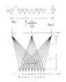
- n individual radiators in the form of horn antennas 10 of an antenna arrangement 1 are schematically arranged side by side, which, which is not shown in detail, rigidly on an aircraft - reproduced in a significantly reduced size - transversely to the direction of flight indicated by an arrow are attached that the main radiation direction of the horn antennas 10 points in the flight direction.
- the processing of the raw data can be carried out in a manner similar to the SAR principle outlined above, with a synthetic aperture length L having to be replaced by half the distance between the first and nth individual radiators of the horn antenna arrangement.
- the send and receive paths are not the same length.
- the respective signal is correlated in terms of amplitude and phase as a function of the distance with a conjugate complex reference function which is given in detail below. It is crucial, however, that the received signal at each individual element 10 has a different phase to the transmit pulse due to the different location between transmitter and receiver. This means that the phase relationship between the individual elements must be constant and known. However, the transmitter is not required to be coherent.
- the distance between the n individual radiators 10 is now Ax, this distance can be expressed by where f is the aperture length of each individual radiator, ⁇ is the wavelength and 0 is the illumination angle, the illumination angle 0 being entered in the illumination geometry shown schematically in FIG. 2.
- the distance r can be expressed as follows, as can be seen from the schematic illustration in FIG. 2: where a is the distance between the antenna center axis 0 and a point target T, x is the distance between the antenna center axis 0 and a single radiator 1 and R is the distance gate distance, as can be seen in detail from the schematic illustration in FIG. 2.
- a received signal S can then be represented as a function of the distance x as follows: where A denotes an amplitude of the received signal S.
- the reference function already mentioned can then be expressed as follows depending on the distance x:
- the correlation between the received signal S (x) and the reference function R (x) is thus: where P denotes the output value of a processor, L the total aperture length between the first and nth individual radiators 10 and k the offset of the reference function R (x) in the correlation, ie the offset between the individual radiators 10.
- the pulse repetition frequency can be chosen as desired. This means that a separate correlation is carried out per radar pulse for each angular range, with the result that the complete sector can be displayed for each radar pulse.
- Raw data for a distance gate can be processed in accordance with a processing scheme shown in FIG.
- the complex received signal value S u applied is multiplied by a reference function value R uv with respect to each individual radiator and the corresponding angle to be resolved.
- R uv the reference function value
- ⁇ the wavelength
- 0 an imaging or illumination angle with R is the distance gate distance
- Ax the distance between the individual radiators 10.
- the flight speed of a carrier carrying the forward view radar system according to the invention is basically of no importance for the recording principle, or in other words, the forward view radar according to the invention is suitable for both stationary and mobile use.
- the flight speed can thus be used to improve the result by averaging the individual, processed data records.
- the transmission sequence ie the pulse repetition frequency (PRF) is of no importance for the forward vision radar according to the invention; however, it must be adapted to the respective measurement sequence.
- PRF pulse repetition frequency
- the resolution Solution perpendicular to the direction of flight of the carrier depending on the distance since according to the invention a fixed antenna length with n individual elements is used.
- the individual values are as follows:
- the number of reference functions marked with a * corresponds to a minimum number deemed useful. Furthermore, the resolution in the flight direction or in the radiation direction depends on the respective pulse length.
- each point is enlarged depending on the distance with the following factor F r : where a denotes the angle of depression, ie the angle between the horizontal and the radiation direction.
- F a the distance of the distance gate to be corrected
- R 1 the distance of the first distance gate.
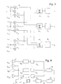
- FIG. 4 shows a block diagram of a forward view imaging radar according to the invention.
- a single individual element for example the individual radiator 10 (7) of the antenna 1, which has a total of n individual elements 10, is connected to a transmitter 7, apart from the individual element 10 (7) , all other individual elements 10 are in series a receiver and an analog-to-digital converter 9 subordinate.
- the outputs of the total (n-1) analog-to-digital converter 9 are applied to a processor 62, the output values of which are brought via a formatter 63 and an image memory 64 to a monitor 65, on which the recorded image data can then be displayed.
- the forward view radar according to the invention can also be used in connection with helicopters for search, rescue and environmental tasks, since no forward speed is required to use the forward view radar according to the invention and the self-movement of a helicopter "standing" at a designated location is insignificant.
- the forward view radar according to the invention in connection with all-round view radar devices, such as, for example, in ship radar or airport radar systems.
- all-round view radar devices such as, for example, in ship radar or airport radar systems.
- several antennas must be used, which must be installed in a very specific geometric arrangement with respect to one another according to the respective application.
- this can be achieved, for example, by four antennas arranged at right angles to one another.
- the forward view radar according to the invention can also be used and used just as well for the detection and measurement of marine pollution, such as oil films and corresponding monomolecular films.
Landscapes
- Engineering & Computer Science (AREA)
- Remote Sensing (AREA)
- Radar, Positioning & Navigation (AREA)
- Physics & Mathematics (AREA)
- Computer Networks & Wireless Communication (AREA)
- General Physics & Mathematics (AREA)
- Electromagnetism (AREA)
- Radar Systems Or Details Thereof (AREA)
- Variable-Direction Aerials And Aerial Arrays (AREA)
Applications Claiming Priority (2)
| Application Number | Priority Date | Filing Date | Title |
|---|---|---|---|
| DE4007611A DE4007611C1 (da) | 1990-03-09 | 1990-03-09 | |
| DE4007611 | 1990-03-09 |
Publications (3)
| Publication Number | Publication Date |
|---|---|
| EP0445795A2 EP0445795A2 (de) | 1991-09-11 |
| EP0445795A3 EP0445795A3 (en) | 1993-04-07 |
| EP0445795B1 true EP0445795B1 (de) | 1995-07-19 |
Family
ID=6401870
Family Applications (1)
| Application Number | Title | Priority Date | Filing Date |
|---|---|---|---|
| EP91103459A Expired - Lifetime EP0445795B1 (de) | 1990-03-09 | 1991-03-07 | Vorwärtssicht-Radar |
Country Status (4)
| Country | Link |
|---|---|
| US (1) | US5132686A (da) |
| EP (1) | EP0445795B1 (da) |
| CA (1) | CA2037710C (da) |
| DE (1) | DE4007611C1 (da) |
Families Citing this family (14)
| Publication number | Priority date | Publication date | Assignee | Title |
|---|---|---|---|---|
| GB2256339B (en) * | 1991-05-31 | 1995-07-19 | Commw Of Australia | A method of reducing tracking errors in determining target tracks of targets ina surveillance area |
| US5243351A (en) * | 1992-06-25 | 1993-09-07 | Hughes Aircraft Company | Full aperture image synthesis using rotating strip aperture image measurements |
| DE4323511C1 (de) * | 1993-07-14 | 1995-01-26 | Deutsche Aerospace | Radargerät zur Hinderniswarnung |
| JPH11510814A (ja) * | 1995-08-30 | 1999-09-21 | ジー.ディー.サール アンド カンパニー | インテグリンアンタゴニストとしてのメタ−グアニジン、尿素、チオ尿素またはアザ環状アミノ安息香酸誘導体 |
| SE517768C2 (sv) * | 1995-09-21 | 2002-07-16 | Totalfoersvarets Forskningsins | Ett SAR-radar system |
| US5614907A (en) * | 1996-03-14 | 1997-03-25 | Daimler-Benz Aerospace Ag | All weather visual system for helicopters |
| US6155704A (en) * | 1996-04-19 | 2000-12-05 | Hughes Electronics | Super-resolved full aperture scene synthesis using rotating strip aperture image measurements |
| DE19749461A1 (de) * | 1997-11-10 | 1999-05-27 | Deutsch Zentr Luft & Raumfahrt | Radarantenne |
| RU2143708C1 (ru) | 1998-12-25 | 1999-12-27 | Коночкин Анатолий Иванович | Способ формирования радиолокационного изображения объекта и устройство формирования радиолокационного изображения |
| DE10035658C2 (de) * | 2000-07-20 | 2002-06-27 | Joao R Moreira | Vorwärtssicht-Radarsystem (FLR; Forward Looking Radar) zur dreidimensionalen Abbildung eines Geländeausschnitts |
| US7009550B2 (en) * | 2003-06-20 | 2006-03-07 | Peter Moeller-Jensen | Method and apparatus for monitoring and measuring oil spills |
| EA007941B1 (ru) * | 2005-07-19 | 2007-02-27 | Федеральное Государственное Унитарное Предприятие "Нижегородский Научно-Исследовательский Институт Радиотехники" | Мобильная рлс кругового обзора метрового диапазона волн |
| DE102010035601B4 (de) | 2010-08-27 | 2012-10-04 | Fraunhofer-Gesellschaft zur Förderung der angewandten Forschung e.V. | Verfahren und Vorrichtung zur Radarabbildung einer Szene in Voraussicht ausgehend von einer bewegten Plattform |
| US8760634B2 (en) | 2011-10-28 | 2014-06-24 | Lockheed Martin Corporation | Optical synthetic aperture radar |
Family Cites Families (2)
| Publication number | Priority date | Publication date | Assignee | Title |
|---|---|---|---|---|
| DE3540808A1 (de) * | 1984-08-22 | 1987-05-21 | Messerschmitt Boelkow Blohm | Einrichtung zur detektion und bekaempfung untergezogener bodenziele |
| DE3430888A1 (de) * | 1984-08-22 | 1986-03-06 | Messerschmitt-Bölkow-Blohm GmbH, 8012 Ottobrunn | Einrichtung zur detektion und bekaempfung untergezogener bodenziele |
-
1990
- 1990-03-09 DE DE4007611A patent/DE4007611C1/de not_active Expired - Lifetime
-
1991
- 1991-03-07 US US07/665,826 patent/US5132686A/en not_active Expired - Fee Related
- 1991-03-07 EP EP91103459A patent/EP0445795B1/de not_active Expired - Lifetime
- 1991-03-07 CA CA002037710A patent/CA2037710C/en not_active Expired - Fee Related
Also Published As
| Publication number | Publication date |
|---|---|
| DE4007611C1 (da) | 1991-05-16 |
| EP0445795A2 (de) | 1991-09-11 |
| CA2037710C (en) | 1994-09-06 |
| CA2037710A1 (en) | 1991-09-10 |
| EP0445795A3 (en) | 1993-04-07 |
| US5132686A (en) | 1992-07-21 |
Similar Documents
| Publication | Publication Date | Title |
|---|---|---|
| EP0445795B1 (de) | Vorwärtssicht-Radar | |
| EP2018577B1 (de) | Hochauflösendes synthetik-apertur-seitensicht-radarsystem mittels digital beamforming | |
| DE60117065T2 (de) | Seitensichtradarsystem mit synthetischer Apertur | |
| EP3803454B1 (de) | Synthetik-apertur-radarverfahren und synthetik-apertur-radarvorrichtung | |
| EP0634668B1 (de) | Radargerät zur Hinderniswarnung | |
| WO2009030339A1 (de) | Synthetik-apertur-radarverfahren | |
| EP0406879B1 (de) | Verfahren zur Extraktion von Bewegungsfehlern eines ein kohärentes Abbildungsradarsystem mitführenden Trägers aus Radar-Rohdaten und Einrichtung zur Durchführung des Verfahrens | |
| EP3425422B1 (de) | Synthetik-apertur-radarverfahren und synthetik-apertur-radarsystem | |
| DE10120536C2 (de) | Radarsystem zur aktiven Hinderniswarnung und Abbildung der Erdoberfläche | |
| DE3885891T2 (de) | Unterdrückung von azimutaler mehrdeutigkeit im sar-signal. | |
| EP0445794B1 (de) | Vorwärtssicht-Radar | |
| EP1746437B1 (de) | Synthetik-Apertur-Radar(SAR)-System | |
| EP1065518B1 (de) | Hochauflösendes Synthetik-Apertur-Radarsystem | |
| DE3731036A1 (de) | Radar mit großem Augenblicks-Feldwinkel und hohem Augenblicks-Winkelauflösungsvermögen, insbesondere für ein Flugkörper-Zielsuchgerät | |
| EP0355336B1 (de) | Radarsystem zur Positionsbestimmung von zwei oder mehreren Objekten | |
| EP0915349B1 (de) | Radarsystem zum Abbilden von Sektoren | |
| DE2835932C2 (de) | Kartographieradargerät | |
| EP0076877B1 (de) | Einrichtung zur Darstellung eines Geländeausschnitts an Bord von Fahrzeugen, insbesondere Luftfahrzeugen | |
| DE69527184T2 (de) | Wiederherstellung des Elevationsrichtens, insbesondere für Radar mit synthetischer Apertur | |
| DE3501952C1 (en) | Method of locating targets by reflected beam - measures frequency of reflected signal using monostatic radar system at transmitter, or multiple remote multistatic radar | |
| DE2532970A1 (de) | Antenne | |
| EP3564708B1 (de) | Synthetik-apertur-radarverfahren zur fernerkundung der erdoberfläche und synthetik-apertur-radarvorrichtung | |
| EP2775317B1 (de) | Verfahren zum Betreiben eines Radarsystems mit synthetischer Apertur im Sende- und Empfangsbetrieb | |
| DE102018120383A1 (de) | Radarsystem mit einer synthetischen Antennenapertur | |
| DE2807977A1 (de) | Radargeraet zur elevationsmessung |
Legal Events
| Date | Code | Title | Description |
|---|---|---|---|
| PUAI | Public reference made under article 153(3) epc to a published international application that has entered the european phase |
Free format text: ORIGINAL CODE: 0009012 |
|
| AK | Designated contracting states |
Kind code of ref document: A2 Designated state(s): FR GB IT |
|
| PUAL | Search report despatched |
Free format text: ORIGINAL CODE: 0009013 |
|
| AK | Designated contracting states |
Kind code of ref document: A3 Designated state(s): FR GB IT |
|
| 17P | Request for examination filed |
Effective date: 19931005 |
|
| 17Q | First examination report despatched |
Effective date: 19950104 |
|
| GRAA | (expected) grant |
Free format text: ORIGINAL CODE: 0009210 |
|
| AK | Designated contracting states |
Kind code of ref document: B1 Designated state(s): FR GB IT |
|
| ITF | It: translation for a ep patent filed | ||
| ET | Fr: translation filed | ||
| GBT | Gb: translation of ep patent filed (gb section 77(6)(a)/1977) |
Effective date: 19951016 |
|
| PLBE | No opposition filed within time limit |
Free format text: ORIGINAL CODE: 0009261 |
|
| STAA | Information on the status of an ep patent application or granted ep patent |
Free format text: STATUS: NO OPPOSITION FILED WITHIN TIME LIMIT |
|
| 26N | No opposition filed | ||
| REG | Reference to a national code |
Ref country code: GB Ref legal event code: IF02 |
|
| PGFP | Annual fee paid to national office [announced via postgrant information from national office to epo] |
Ref country code: GB Payment date: 20050223 Year of fee payment: 15 |
|
| PG25 | Lapsed in a contracting state [announced via postgrant information from national office to epo] |
Ref country code: IT Free format text: LAPSE BECAUSE OF NON-PAYMENT OF DUE FEES;WARNING: LAPSES OF ITALIAN PATENTS WITH EFFECTIVE DATE BEFORE 2007 MAY HAVE OCCURRED AT ANY TIME BEFORE 2007. THE CORRECT EFFECTIVE DATE MAY BE DIFFERENT FROM THE ONE RECORDED. Effective date: 20050307 |
|
| PGFP | Annual fee paid to national office [announced via postgrant information from national office to epo] |
Ref country code: FR Payment date: 20050318 Year of fee payment: 15 |
|
| PG25 | Lapsed in a contracting state [announced via postgrant information from national office to epo] |
Ref country code: GB Free format text: LAPSE BECAUSE OF NON-PAYMENT OF DUE FEES Effective date: 20060307 |
|
| GBPC | Gb: european patent ceased through non-payment of renewal fee |
Effective date: 20060307 |
|
| REG | Reference to a national code |
Ref country code: FR Ref legal event code: ST Effective date: 20061130 |
|
| PG25 | Lapsed in a contracting state [announced via postgrant information from national office to epo] |
Ref country code: FR Free format text: LAPSE BECAUSE OF NON-PAYMENT OF DUE FEES Effective date: 20060331 |