EP0445293A1 - Heterodynes photodetektorsystem und dieses photodetektorsystem benutzendes abbildungssystem für transmissionsbilder - Google Patents
Heterodynes photodetektorsystem und dieses photodetektorsystem benutzendes abbildungssystem für transmissionsbilder Download PDFInfo
- Publication number
- EP0445293A1 EP0445293A1 EP90908662A EP90908662A EP0445293A1 EP 0445293 A1 EP0445293 A1 EP 0445293A1 EP 90908662 A EP90908662 A EP 90908662A EP 90908662 A EP90908662 A EP 90908662A EP 0445293 A1 EP0445293 A1 EP 0445293A1
- Authority
- EP
- European Patent Office
- Prior art keywords
- light
- receptor
- image
- diffraction image
- receptor element
- Prior art date
- Legal status (The legal status is an assumption and is not a legal conclusion. Google has not performed a legal analysis and makes no representation as to the accuracy of the status listed.)
- Granted
Links
- 230000005540 biological transmission Effects 0.000 title claims description 12
- 238000001514 detection method Methods 0.000 title description 10
- 230000003287 optical effect Effects 0.000 claims abstract description 81
- 238000001228 spectrum Methods 0.000 claims abstract description 40
- 230000001427 coherent effect Effects 0.000 claims description 11
- 230000001902 propagating effect Effects 0.000 claims description 8
- 239000013307 optical fiber Substances 0.000 claims description 4
- 239000011358 absorbing material Substances 0.000 claims 1
- 239000006096 absorbing agent Substances 0.000 abstract description 5
- 230000010355 oscillation Effects 0.000 abstract description 4
- 230000015572 biosynthetic process Effects 0.000 description 9
- 230000006870 function Effects 0.000 description 8
- 238000010276 construction Methods 0.000 description 6
- 230000031700 light absorption Effects 0.000 description 6
- 210000001519 tissue Anatomy 0.000 description 6
- 238000010521 absorption reaction Methods 0.000 description 5
- 238000002591 computed tomography Methods 0.000 description 5
- 210000003128 head Anatomy 0.000 description 5
- 238000000034 method Methods 0.000 description 5
- 238000002835 absorbance Methods 0.000 description 4
- 238000005286 illumination Methods 0.000 description 4
- 210000001747 pupil Anatomy 0.000 description 4
- 238000000926 separation method Methods 0.000 description 4
- 102000001554 Hemoglobins Human genes 0.000 description 3
- 108010054147 Hemoglobins Proteins 0.000 description 3
- 238000004458 analytical method Methods 0.000 description 3
- 230000002238 attenuated effect Effects 0.000 description 3
- 239000008280 blood Substances 0.000 description 3
- 210000004369 blood Anatomy 0.000 description 3
- 210000000481 breast Anatomy 0.000 description 3
- 238000003384 imaging method Methods 0.000 description 3
- 230000015654 memory Effects 0.000 description 3
- 238000002156 mixing Methods 0.000 description 3
- 238000005316 response function Methods 0.000 description 3
- 230000001360 synchronised effect Effects 0.000 description 3
- 230000004304 visual acuity Effects 0.000 description 3
- 241000282326 Felis catus Species 0.000 description 2
- 238000006243 chemical reaction Methods 0.000 description 2
- 230000007423 decrease Effects 0.000 description 2
- 238000003745 diagnosis Methods 0.000 description 2
- 239000000835 fiber Substances 0.000 description 2
- 239000012530 fluid Substances 0.000 description 2
- 230000010354 integration Effects 0.000 description 2
- 238000013507 mapping Methods 0.000 description 2
- 210000000653 nervous system Anatomy 0.000 description 2
- 230000035945 sensitivity Effects 0.000 description 2
- 230000009466 transformation Effects 0.000 description 2
- 206010006187 Breast cancer Diseases 0.000 description 1
- 208000026310 Breast neoplasm Diseases 0.000 description 1
- OKTJSMMVPCPJKN-UHFFFAOYSA-N Carbon Chemical compound [C] OKTJSMMVPCPJKN-UHFFFAOYSA-N 0.000 description 1
- 241000282412 Homo Species 0.000 description 1
- 241001465754 Metazoa Species 0.000 description 1
- 102100025490 Slit homolog 1 protein Human genes 0.000 description 1
- 101710123186 Slit homolog 1 protein Proteins 0.000 description 1
- 230000004075 alteration Effects 0.000 description 1
- QVGXLLKOCUKJST-UHFFFAOYSA-N atomic oxygen Chemical compound [O] QVGXLLKOCUKJST-UHFFFAOYSA-N 0.000 description 1
- 230000035559 beat frequency Effects 0.000 description 1
- 210000002449 bone cell Anatomy 0.000 description 1
- 229910052799 carbon Inorganic materials 0.000 description 1
- 210000004027 cell Anatomy 0.000 description 1
- 230000002490 cerebral effect Effects 0.000 description 1
- 238000007796 conventional method Methods 0.000 description 1
- 230000001419 dependent effect Effects 0.000 description 1
- 238000009792 diffusion process Methods 0.000 description 1
- 238000000605 extraction Methods 0.000 description 1
- 239000003925 fat Substances 0.000 description 1
- 239000003365 glass fiber Substances 0.000 description 1
- 238000005534 hematocrit Methods 0.000 description 1
- 230000006872 improvement Effects 0.000 description 1
- 230000002452 interceptive effect Effects 0.000 description 1
- 230000001678 irradiating effect Effects 0.000 description 1
- 238000005259 measurement Methods 0.000 description 1
- 230000004048 modification Effects 0.000 description 1
- 238000012986 modification Methods 0.000 description 1
- 229910052760 oxygen Inorganic materials 0.000 description 1
- 239000001301 oxygen Substances 0.000 description 1
- 238000007781 pre-processing Methods 0.000 description 1
- 238000012545 processing Methods 0.000 description 1
- 230000005855 radiation Effects 0.000 description 1
- 238000002601 radiography Methods 0.000 description 1
- 230000029058 respiratory gaseous exchange Effects 0.000 description 1
- 239000004065 semiconductor Substances 0.000 description 1
- 239000007787 solid Substances 0.000 description 1
- 230000003595 spectral effect Effects 0.000 description 1
- 230000002792 vascular Effects 0.000 description 1
Images


Classifications
-
- G—PHYSICS
- G01—MEASURING; TESTING
- G01N—INVESTIGATING OR ANALYSING MATERIALS BY DETERMINING THEIR CHEMICAL OR PHYSICAL PROPERTIES
- G01N21/00—Investigating or analysing materials by the use of optical means, i.e. using sub-millimetre waves, infrared, visible or ultraviolet light
- G01N21/17—Systems in which incident light is modified in accordance with the properties of the material investigated
- G01N21/59—Transmissivity
-
- G—PHYSICS
- G01—MEASURING; TESTING
- G01J—MEASUREMENT OF INTENSITY, VELOCITY, SPECTRAL CONTENT, POLARISATION, PHASE OR PULSE CHARACTERISTICS OF INFRARED, VISIBLE OR ULTRAVIOLET LIGHT; COLORIMETRY; RADIATION PYROMETRY
- G01J9/00—Measuring optical phase difference; Determining degree of coherence; Measuring optical wavelength
- G01J9/04—Measuring optical phase difference; Determining degree of coherence; Measuring optical wavelength by beating two waves of a same source but of different frequency and measuring the phase shift of the lower frequency obtained
-
- G—PHYSICS
- G01—MEASURING; TESTING
- G01N—INVESTIGATING OR ANALYSING MATERIALS BY DETERMINING THEIR CHEMICAL OR PHYSICAL PROPERTIES
- G01N21/00—Investigating or analysing materials by the use of optical means, i.e. using sub-millimetre waves, infrared, visible or ultraviolet light
- G01N21/17—Systems in which incident light is modified in accordance with the properties of the material investigated
- G01N2021/178—Methods for obtaining spatial resolution of the property being measured
- G01N2021/1785—Three dimensional
- G01N2021/1787—Tomographic, i.e. computerised reconstruction from projective measurements
Definitions
- This invention relates to a heterodyne receptor system capable of detecting with high resolution information light buried in scattered light and an arrangement capable of visualizing optical transmission images.
- an object O shown in Fig. 22 does not contain too much scatterers and is relatively close to transparency. Then, light having a specific wavelength component selected through a filter 340 is directed onto the object O from a ring type of slit 341 placed at the focal position of a lens L1, so that the enlarged image can be focused onto a plane P through an objective L2 for observation.
- the use of the ring type of slit 341 located at the focal point of the lens L1 is tantamount to irradiating the object O with light in every direction, as shown in Fig. 23, so that images I1, I2, and so on, of the object O in the respective directions can be observed at once.
- FIG. 24 The construction of a conventional system for obtaining a light absorption distribution image is illustrated in Fig. 24, wherein reference numeral 401 stands for a scan head, 403 the human body, 405 a video camera, 407 an A/D converter, 409 a near infrared light frame memory, 411 a red light frame memory, 413 a processor, 415 a color conversion processor, 417 an encoder keyboard, 419 a D/A converter, 421 a printer, 423 a TV monitor and 425 a video tape recorder.
- the spot of the human body to be inspected e.g.
- the mamma is irradiated and scanned alternately with red light (strongly absorbed in hemoglobin in the blood in particular) and near infrared light (absorbed in the blood, fluids, fat, etc.) by the scan head 401 through a light guide.
- red light strongly absorbed in hemoglobin in the blood in particular
- near infrared light absorbed in the blood, fluids, fat, etc.
- the spot is illuminated with light from below.
- the mamma glows brightly, and the transmission image is picked up by the video camera 401. That image is converted through the A/D convertor 407 into digital signals, and the near infrared light and red light are fed in the frame memories 409 and 411, respectively, through a digital switch.
- the ratio of intensities of near infrared light and red light is then computed in the processor 413, and is further converted into analog signals by color conversion processing.
- the resulting light absorption distribution image is finally observed through a printer, a TV monitor or a video
- Fig. 25 is a diagrammatic sketch illustrating the construction of a a conventional unit for obtaining light absorption distribution images using a collimated illuminator/receptor system.
- laser light emanating from a light source is guided onto an object 435 to be inspected through an optical fiber 433 for illumination, and the transmitted light is picked up by a fiber collimator 437 and fed into a receptor 443 wherein it is converted into electrical signals, which are in turn processed in an computer 451 through a pre-processing circuit 445, an A/D converter 447 and an interface 449.
- scanning is carried out while the optical fiber 433 for illumination are synchronized with the fiber collimator 437 for detection by a motor 439, thereby obtaining light absorption distribution images of the respective spots of the object, which are in turn observed on a monitor 453.
- the red light source used is a 633-nm He-Ne laser and the near infrared light source used an 830-nm semiconductor laser.
- the near infrared light source used an 830-nm semiconductor laser.
- Jobsis and coworkers reported in 1977 that they could succeeded in detecting light transmitted through the heads of cats or humans illuminated with near infrared light and the amount of that transmitted light were found to vary depending upon the animals' respiration.
- near infrared light having a wavelength of 700 to 1500 nm and a tissue specimen, nearly the size of the head of a cat, the transmitted light could be well detected at a dose of about 5 mW. This dose is greately safe, because it is about 1/50 or less of the present safety standards for laser, or about 1/10 of near infrared light to which we are now being exposed at the seaside.
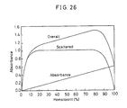
- Fig. 26 is the Twersky's scattering theory curves that clarifies the relationship between the absorbance of an erythrocite-suspending fluid and the concentration of hematocrit, and shows the intensity, scattered and absorbance components of the transmitted light obtained by illumination of laser light having a wavelength of 940 nm.
- the transmitted light has the large scattered component superposed on the absorbance component.
- the scattered component because of being directionality-free, has the property of coming to contain scattered light from various spots and making optical tomograms blurry. For this reason, mere detection of the transmitted light does not allow the absorbance component, that is the required information, to be detected with high accuracy.
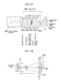
- Fig. 27 is a diagrammatic sketch illustrating the optical properties of such a specimen as a living body.
- the object O contains no scattering component.
- a specimen 460 of Fig. 27, that is to be actually observed should be essentially considered to be made up of a Rayleigh scatterer 460a enough small to the wavelength of light; a Mie scatterer 460b nearly the size of the wavelength of light; a light transmission information carrier 460c that is the target to be observed and absorbs light; a diffuser 460d that diffuses light; a diffraction grating 460e that gives rise to random diffraction; and so on.
- Fig. 28 is a diagrammatic sketch illustrating a Fresnel diffraction wave produced by a sinusoidal grating having a finite aperture.
- Fig. 29 is diagrammatic sketches illustrating a luminance distribution found on a plane of view located in opposition to a random scatterer, when it is illuminated with coherent light.
- Fig. 30 is diagrammatic sketch showing a luminance distribution of reflected light that depends on what state a diffuse reflection plane is in, with Figs. 30a and 30b taking the form of polar and rectangular coordinates, respectively.
- J stands for a luminance distribution of light reflected from a perfect diffusion plane
- G denotes a luminance distribution of light reflected from a glossy plane
- P indicates a luminance distribution of light reflected from a dim plane.
- the luminance distribution shows a peak converging sharply in the predetermined direction, while on the dim plane the luminance distribution is diverging.
- the present invention has for its object to provide a heterodyne receptor system capable of detecting the required information light from many scattered components with the use of a short receptor element, even when information light is buried therein, whereby optical tomograms of a living body or the like can be imaged, and an arrangement for imaging optical tomograms.
- a heterodyne receptor system characterized by including laser transmitted through a sample, mixing means for mixing said laser light with another laser light having a frequency different from that of said laser light, a receptor element which the resulting light enters and divides a light propagating zone into a plurality of sub-zones and a detector for detecting a beat component of the mixed light out of light leaving said receptor element, said receptor element having an exit end, at which a spatial zone, which is defined between different points and in which interference occurs, is limited within a spatially resolvable minimum unit to detect the beat component of the mixed light.
- an arrangement for visualizing optical transmission images characterized by including a stage for moving a sample, means for directing one of two laser beams with a given frequency difference therebetween onto said sample and mixing the transmitted light with the other laser light, a receptor element which the resulting light enters and include a plurality of divided, light propagating zones and a detector for detecting a beat component of the mixed light out of light leaving said receptor element, means for computing the detected signals, and means for displaying the result of said computing, whereby a beat component is extracted from light leaving said sample to visualize an optical transmission image.
- laser light transmitted through a sample is mixed with laser light different in frequency therefrom, and the resulting light is received by a receptor element which divides a light propagating zone into a plurality of sub-zones, each of said sub-zones being limited within a spatially resolvable minimum unit in which interference occurs between different points, thereby forming a Fraunhofer diffraction image to detect the n order diffraction images at most.
- a receptor element which divides a light propagating zone into a plurality of sub-zones, each of said sub-zones being limited within a spatially resolvable minimum unit in which interference occurs between different points, thereby forming a Fraunhofer diffraction image to detect the n order diffraction images at most.
- the size of a pinhole through which diffraction images are extracted is fixed on the mm order, on which an misalignment of an optical system due to vibration or fluctuation is negligible, thereby extracting a spectrum at most n times the 0 order light. Then, the beat component is extracted from the mixed light to separate a transmission image from scattered components for detection.
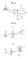
- Fig. 5a assume that light from a minuscule light source dx located at a point X on a plane ⁇ is coherent and passes through a lens Lc and an object O to form a spectrum O(s) on a plane L, the center (0 frequency) of which is found at X. Since ⁇ and L are shown on the same coordinates X on which the origin of O(s) is found, the component capable of passing through L is a portion of that. As illustrated in Fig.
- Equation (3) may also be interpreted as follows. That is, the complex amplitude o'(u') of the image on the imagewise plane is given by It is noted, however, that the variable s in Equation (4) is changed to s'. It is also understood that although the pupil function is finite, it is otherwise 0 so that the lower and upper limits of integration are fixed at ⁇ .
- Equation (11) means that if the object spectrum is expressed as O(s), then the image I(u') is found by integrating the total frequency with respect to the product of the interference fringe formed by a beat between the spectra O(f') and O*(f'') multiplied by the weight T(f', f''). Referring to T(f',f'') that is not a function of f'-f'' alone, f' and f'' vary with position, even when f'-f'' is constant.
- This function T(f) is called a response function.
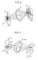
- the light is directed through a minuscule zone 5 in an object plane ⁇ o and a lens system 2 onto an image-forming plane ⁇ i to produce an image on a point 4 thereon, as shown in Fig. 7.
- the light intensity on the imagery plane is converged into the point 4, giving a sharp peak. Accordingly, the respective points of the object are imaged on the image-forming plane independently or without interfering with one another.
- T(f', f'') const.
- This function T(f) is called a response function.
- the transmitted light diverges in the form of plane diffraction waves that propagate in the same direction as does the incident light.
- the radiation pattern of the scattered light takes a spherical form and that of the transmitted light, propagating in the form of plane diffraction waves, is of sharp directionality.
- a Fraunhofer diffraction image is then found.
- the plane waves show a intensity distribution in which the 0 order spectrum is very large in magnitude but other higher order spectra are small.
- Scattered light 18 by a gathering of spherical waves shows a flat form of intensity distribution, as illustrated.
- scattered light 19 also shows a diffraction pattern in which the 0 order spectrum is relatively large in magnitude.
- the scattered light is so attenuated, as can be seen from Fig. 8a, that the 0 order spectrum of the plane wave can be sufficiently increased in magnitude.
- the 0 order diffraction images of Fruaunhofer diffraction images formed through that lent may be smaller or larger the lens aperture, although this is dependent upon how to combine the focal length with the aperture's size.
- heterodyning is agains employed as means for extracting only the 0 order diffraction light wholly or partly to make separation between scattered light and transmitted light.
- the heterodyne system designed to extract a portion of the 0 order diffraction light is inferior in the minimum detection sensitivity to that designed to extract the 0 order diffraction light in its entirety.
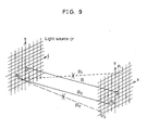
- a light source ⁇ is spaced away by a distance R from a plane P on which a Fraunhofer diffraction image is observable.
- the intensity of light from a minuscule light source S ij on the plane P is detected only with respect to P ij in the axial direction corresponding to the source S ij , and not with respect to other positions such as P1 and P2.
- FIG. 10 one of Fraunhofer diffraction images formed through a round aperture is shown in Fig. 10, in which the wave forms shown by solid and broken lines stand for field and light intensities, respectively.
- a Fraunhofer diffraction image as shown in Fig. 10a is observed at a position sufficiently afar off.
- Fig. 10b this is made up of a plurality of dark rings - called the Airy's disk - and bright zones between the respective dark rings.
- An inside zone A of the first dark ring or, in a better term, the 0 order spectrum zone, is the brightest of all.
- a Fraunhofer diffraction image In the case of a plane wave, the condition for forming a Fraunhofer diffraction image is represented by z » r2 max /2 ⁇ (12) wherein r is the aperture diameter of a light source and z is the propagation distance.
- a Fraunhofer diffraction image may be formed at such a distance as to meet Equation (12) for heterodyning through a pinhole n times as large as the 0 order spectrum thereof.
- a Fraunhofer diffraction image formed through a pinhole defined by a round aperture is given by where Dr is the radius of the pinhole, J1 the Bessel function, ⁇ the wavelength and z the optical axis length.
- detection can then be made at a 16% loss of the plane wave. Since a spherical wave be attenuated in inverse proportion to the square of distance, on the other hand, it is possible to make observation of an image of high resolution by extracting only the 0 order spectrum of the Fraunhofer diffraction image.
- the present invention is designed such that a Fraunhofer diffraction image of light obtained by photomixing of laser light transmitted through a sample with light from a local oscillator is observed for the beat component to detect only the 0 order spectrum of the Fraunhofer diffraction image with the use of a relatively short receptor system having a relatively large pinhole diameter.
- Fig. 1 is a diagrammatic sketch illustrating the construction of this invention.
- reference numeral 01 stands for a laser light source, S a specimen, 02 a local oscillator source of light, 03 a half mirror, 04 an optical system of high directionality, 05 a photodetector and 06 a filter.
- the laser light source 01 and the local oscillator source 02 differ in wavelength.
- Light from the light source 01, which has passed through the sample S, is photomixed with light from the local oscillator source 02, and the resulting light is received by the optical system of high directionality to be described later.
- the optical system 04 for instance, includes pinholes P1 and P2.
- the photodetector 05 is used to detect a Fraunhofer diffraction image, and the beat component of light from both the light source 01 and the local oscillator source 02 is detected by the filter 6.
- the amplitude of the signal light of the Fraunhofer diffraction image is determined by whether the aperture is in round, rectangular or annular forms.
- the beat component detected through the filter 06 is defined by a hatched region therein. Since the beat component is detected as the product of the Fraunhofer images A1 and A2, it is corresponding to the area of the overlapping regions of the 0 order spectra. This area reaches a maximum when A1 and A2 are in agreement with each other, and decreases as the amount of overlapping decreases.
- any higher order component cannot be detected because the signals detected are made up of the beat component.
- the signal intensity of this beat component which varies depending upon a combination of the aperture geometries for the received light and the light from the local oscillator, is determined in the form of the product of both the amplitudes, as shown in Fig. 3, and reaches a maximum when the aperture geometry for the received light coincides with that for the light from the local oscillator. For heterodyning, it is thus preferred that both the apertures coincide with each other in geometery. However, this is a matter of choice that is determined by for what purpose measurement is made.
- Figs. 11 to 15 illustrate an optical system of high directionality, which serves as a receptor element for selecting a diffraction image n times in magnitude as large as the 0 order spectrum of a Fraunhofer diffraction image at the exit end thereof.
- Fig. 11 illustrates one embodiment of the high-directionality optical system having an aperture according to this invention, which serves as a receptor element for detecting a diffraction image.
- Laser light is directed from a light source 20 onto a sample 21, the transmitted light from which is passed through a slit P1 and thence through a slit P2 spaced away from it by such a distance 1 as to satisfy Equation (12), to detect the 0 order light by a detector 23.
- the pinhole diameter D may be several times as large as that value.
- Fig. 12 is a diagrammatic sketch illustrating another embodiment of the high-directionality optical system, wherein reference numeral 30 stands for an optical element of high directionality, 33 a light absorber, 35 a core and 37 a clad.
- the optical element 30, for instance may be formed of a linear, elongated, hollow glass fiber, the inner wall of which is coated with such a light absorber as carbon.
- the aperture diameter and length of the high-directionality optical element are preset depending upon the object to be measured and that length is enough long relative to that aperture diameter, then it is possible to extract only plane waves parallel with the optical axis from light waves entering the optical element.
- the diameter of the optical element be larger than the wavelength of incident light. If the optical element should have a diameter nearly equal to the wavelength of incident light, so large would the amount of diffraction be that the quantity of light extracted is extremely reduced.
- the optical element can also be increased in diameter by using the heterodyne receptor system.
- the separating power is on the same level, because the beat component is of the same zero order as mentioned above.
- the index of refraction of the core section is made smaller than that of the rest.
- Light beams at angles with the optical axis dissipate without being subjected to total reflection. Even through a part of them is reflected, all this comes to disappear from the optical element while reflection is repeated several times. It is thus possible to detect all plane waves but scattered components.
- Fig. 13 is a diagrammatic sketch illustrating a further embodiment of this invention, in which a lens is used.
- a lens 25 is used to form a Fraunhofer diffraction image through an aperture on the front focal plane and focus it onto the back focal plane, whereby the length of a receptor system can be reduced.
- the use of this embodiment in combination with heterdyning according to this invention enables the length of the receptor system to be further reduced.
- Fig. 14 is a diagrammatic sketch illustrating an embodiment of the microscopic optical system for optical computer tomography.
- laser light is converged through a condenser lens L1 onto a sample O.
- the sample is then located in the vicinity of the front focal point of an objective L2 for observation on an enlarged scale.
- the Fraunhofer diffraction image of the sample O is formed through the objective L2 on the back focal point F.
- the size of the resulting 0 order diffraction image is then considered tantamount to a Fraunhofer diffraction image formed through the objective L2 when plane waves enter an aperture equal in size to the 0 order diffraction image on the focal plane of the condenser lens L1 (which is found within the sample plane).
- the size of the 0 order diffraction image exceeds the order of millimeter.
- the incoming light is brought in wavefront alignment with light from a local oscillator on the focal plane or a position before or after it, where heterodyning takes place.
- a reduced image that is the Fourier transformation image of the 0 order diffraction image is formed on the focal plane through an eyepiece L3, which is extracted through a pinhole P for heterodyning.
- the size D of the 0 order diffraction image on this pinhole becomes D ⁇ ⁇ f2/D2 wherein f2 and D2 are the focal length and aperture of the eyepiece L3, respectively.
- D may be made smaller or larger than the size of the 0 order diffraction image on the the plane O of the sample by selecting the F value of the lens L3 - f2/D2.
- the sample's plane may be scanned with laser light.
- broken lines represent optical paths for scattered light, which diffuses in the form of spherical waves and is attenuated.
- Fig. 15 is a diagrammatic sketch illustrating an embodiment of the high-resolution optical system comprising a bundle of a plurality of the optical systems of high directionality according to this invention, with which a general image of an sample can be viewed at once.
- An optical unit 60 for instance, is built of a plurality of such optical elements 61 as described in connection with Figs. 11 to 14, and has such a length l as to satisfy Equation (12).
- the aperture D of this unit is such that a diffraction image at most n times as large as the 0 order spectrum is extractable from Fraunhofer diffraction images.
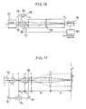
- Fig. 16 is a diagrammatic sketch illustrating an embodiment of the high-directionality optical system comprising a lens and pinholes, which is used in combination with heterodyning.
- light form a laser light source 71 is divided by a half mirror into two portions. One light portion is directed onto a sample S, while the other is photomixed with the light transmitted through the sample S by way of a mirror 73, a phase shifter 74 and a mirror 75.
- the light passing through the phase shifter 74 has its frequency shifted, and photomixed with the rectilinearly propagating light, entering a receptor system through an aperture P1.
- a long-focus lens 78 has its front focal plane located at the aperture position, and a Fraunhofer diffraction image formed through the aperture is extracted through a pinhole P2 located on the back focal plane of the long-focus lens, the beat component of which is in turn detected by a detector 79. Detection of the beat component is synchronized with the operating cycle of a chopper 77, thereby removing such gradual variations as power or temperature variations. And the use of the long-focus lens enables the length of the receptor to be reduced.
- Fig. 17 is a diagrammatic sketch illustrating an embodiment of the microscopic optical system for optical computer tomography.
- laser light is splitted into two laser beams by a half mirror.
- One laser beam is converged through a condenser lens L1 onto a sample O placed in the vicinity of the front focus of an objective L2, while the other laser beam is frequency-shifted by a phase shifter and photomixed on a half mirror 76 with the light from the objective.
- the resulting image is then enlarged through an eyepiece L3 whose front focus is located at the back focus position of the objective L2, with its beat component being detected through a pinhole in a plane P.
- f1 and f2 represent the focal lengths of the objective and eyepiece, respectively.
- the Fraunhofer diffraction image observed satisfies the relation f2 » f1.
- the sample's plane may be scanned with laser light.
- Fig. 18 is a diagrammatic sketch illustrating another embodiment of the microscopic optical system for optical computer tomography.
- This embodiment is similar to that of Fig. 17 with the exception that the mixed light is intermitted by a chopper 77 and detection of the beat component is synchronized with an intermittence cycle.
- FIG. 19 there is shown an embodiment of the optical unit made up of a bundle of a plurality of optical elements, each having a lens, on the focal plane of which a Fraunhofer diffraction is formed, thereby reducing the length of the optical system.
- Photomixed light of received light with local oscillation light is allowed to enter each of the optical elements. It is thus possible to detect the beat component with a relatively short optical system and obtain an optical tomogram of high resolution.
- Fig. 20 is a diagrammatic sketch illustrating an embodiment wherein an image of such an object as a living body is observed with the heterodyning and high-directionality optical system according to this invention.
- Light from a laser light source 181 is divided by a half mirror into two laser beams.
- One laser beam is directed onto an absorber 170a buried between scatterers 170b and 170c, while the other laser beam is frequency-shifted through a phase shifter for photomixing with the transmitted beam.
- the resulting beam is directed through a high-directionality optical system 100 built of a bundle of a plurality of receptor elements according to this invention, and the beat component of the formed Fraunhofer diffraction image is detected by a detector 180. With such an arrangement, it is possible to observe an optical tomogram of the human body or the like with high resolution.
- Fig. 21 is a diagrammatic sketch illustrating one embodiment of the arrangement for imaging optical tomograms, in which the optical system of this invention is incorporated.
- Laser light from an He-Ne laser 200 is divided by a half mirror 201 into two laser beams, which are then frequency-modulated by acoustooptic modulators 203 and 204 driven by modulators 205 and 206 to make a frequency difference f between them. Then, a beam leaving the modulator 204 is directed through an objective 208 onto a sample 212 driving by a pulse stage.
- the transmitted beam is photomixed with a beam passing through an objective 207 and a mirror 209 by a beam splitter 213, entering a high-directionality optical system 214, whence it is processed in a receptor 215, amplified by an amplifier 216 and spectrum-analyzed in a spectral analyzer 218 and processed through a filter 218 having a zone f to detect the beat component.
- the beat component bears information about an transmission image buried in the scattered components. While the sample is moved by the pulse stage 212, the beat component is detected and image-processed in a computer 200 to display an optical tomogram on a CRT 219. If required, this image is printed out with a printer 221.
- signal light and local oscillation light are photomixed together, and the beat component of the resulting light is detected, whereby any higher order component can be cut off, even when a spectrum n times as large as the 0 order spectrum is extracted out of Fraunhofer diffraction images.
- heterodyning is used with a pinhole having an increased diameter, thereby fixing the aperture of the receptor system at a practical value.
- the present invention is applicable to optical computer tomography, etc. If this invention is applied to the human body or the like, it is then possible to view only a vascular image of the human body by using a wavelength corresponding to the absorption region of hemoglobin, to make observation of an image of a nervous system by using light at a wavelength corresponding to the absorption wavelength of the nervous system, or to make clear images of specific cells having a given absorption wavelength such as cerebral or bone cells by illuminating them with light having that absorption wavelength.
- this invention makes breakthroughs in medical or like other techniques.
Applications Claiming Priority (3)
| Application Number | Priority Date | Filing Date | Title |
|---|---|---|---|
| JP250036/89 | 1989-09-26 | ||
| JP1250036A JPH0621868B2 (ja) | 1989-09-26 | 1989-09-26 | ヘテロダイン検波結像系及び該結像系を用いた光断層像画像化装置 |
| PCT/JP1990/000694 WO1991005239A1 (en) | 1989-09-26 | 1990-05-30 | Light receiving system of heterodyne detection and image forming device for light transmission image using said light receiving system |
Publications (3)
| Publication Number | Publication Date |
|---|---|
| EP0445293A1 true EP0445293A1 (de) | 1991-09-11 |
| EP0445293A4 EP0445293A4 (en) | 1992-06-03 |
| EP0445293B1 EP0445293B1 (de) | 1997-08-13 |
Family
ID=17201875
Family Applications (1)
| Application Number | Title | Priority Date | Filing Date |
|---|---|---|---|
| EP90908662A Expired - Lifetime EP0445293B1 (de) | 1989-09-26 | 1990-05-30 | Heterodynes photodetektorsystem und dieses photodetektorsystem benutzendes abbildungssystem für transmissionsbilder |
Country Status (5)
| Country | Link |
|---|---|
| US (1) | US5249072A (de) |
| EP (1) | EP0445293B1 (de) |
| JP (1) | JPH0621868B2 (de) |
| DE (1) | DE69031268T2 (de) |
| WO (1) | WO1991005239A1 (de) |
Cited By (2)
| Publication number | Priority date | Publication date | Assignee | Title |
|---|---|---|---|---|
| EP0449597A2 (de) * | 1990-03-26 | 1991-10-02 | Research Development Corporation Of Japan | Optisches Richtsystem für optisches Teilbildwiedergabegerät |
| EP0585620A1 (de) * | 1992-07-31 | 1994-03-09 | Fuji Photo Film Co., Ltd. | Verfahren und Gerät zum Erhalten drei-dimensionaler Information von Proben |
Families Citing this family (6)
| Publication number | Priority date | Publication date | Assignee | Title |
|---|---|---|---|---|
| JP3019284B2 (ja) * | 1992-08-10 | 2000-03-13 | シャープ株式会社 | 空間光伝送装置 |
| JP2708381B2 (ja) * | 1994-09-30 | 1998-02-04 | 文男 稲場 | 光画像計測装置 |
| US6118396A (en) * | 1997-12-24 | 2000-09-12 | Massachusetts Institute Of Technology | Optically sampling, demultiplexing, and A/D converting system with improved speed |
| US20090289833A1 (en) * | 2008-05-23 | 2009-11-26 | Johnson Paul A | Sparse array millimeter wave imaging system |
| US8471193B2 (en) | 2009-03-05 | 2013-06-25 | Olympus Corporation | Photodetection device for detecting low temporal coherence light, photodetection method, microscope and endoscope |
| JP5390953B2 (ja) * | 2009-06-19 | 2014-01-15 | 株式会社クボタ | 粉粒体の内部品質計測装置 |
Citations (2)
| Publication number | Priority date | Publication date | Assignee | Title |
|---|---|---|---|---|
| EP0082050A1 (de) * | 1981-12-07 | 1983-06-22 | Thomson-Csf | Einrichtung zur Heterodyndetektion eines optischen Bildes |
| WO1989000281A1 (fr) * | 1987-07-03 | 1989-01-12 | General Electric Cgr S.A. | Systeme d'imagerie par transillumination utilisant les proprietes d'antenne de la detection heterodyne |
Family Cites Families (18)
| Publication number | Priority date | Publication date | Assignee | Title |
|---|---|---|---|---|
| JPS5198072A (en) * | 1975-02-25 | 1976-08-28 | Heterodainhoshiki reeza reedasochi | |
| JPS5335568A (en) * | 1976-09-13 | 1978-04-03 | Agency Of Ind Science & Technol | Measuring method of tool abrasion by light reflection |
| US4195221A (en) * | 1978-07-03 | 1980-03-25 | The United States Of America As Represented By The Secretary Of The Navy | Scanning focused local oscillator optical heterodyne imaging system |
| US4193088A (en) * | 1978-08-02 | 1980-03-11 | The United States Of America As Represented By The Secretary Of The Navy | Optical heterodyne system for imaging in a dynamic diffusive medium |
| DE2852978C3 (de) * | 1978-12-07 | 1981-06-04 | Raimund Dr. 4005 Meerbusch Kaufmann | Vorrichtung zur spektroskopischen Bestimmung der Geschwindigkeit von in einer Flüssigkeit bewegten Teilchen |
| US4305666A (en) * | 1979-10-24 | 1981-12-15 | Massachusetts Institute Of Technology | Optical heterodyne detection system and method |
| FR2482325A1 (fr) * | 1980-05-08 | 1981-11-13 | Thomson Csf | Systeme optique d'observation en temps reel a balayage |
| JPS6259841A (ja) * | 1985-09-10 | 1987-03-16 | Res Dev Corp Of Japan | 直線偏光を用いる免疫反応の測定方法および装置 |
| US4707135A (en) * | 1986-01-10 | 1987-11-17 | Rockwell International Corporation | Apparatus and method for the recording and readout of multiple exposure holograms |
| CH678108A5 (de) * | 1987-04-28 | 1991-07-31 | Wild Leitz Ag | |
| JPS6475928A (en) * | 1987-09-17 | 1989-03-22 | Hamamatsu Photonics Kk | Optical heterodyne detector |
| US4820047A (en) * | 1987-12-22 | 1989-04-11 | Snyder James J | Laser heterodyne apparatus for measuring optical power |
| US4950070A (en) * | 1988-04-08 | 1990-08-21 | Kowa Company Ltd. | Ophthalmological diagnosis method and apparatus |
| JPH01262835A (ja) * | 1988-04-15 | 1989-10-19 | Kowa Co | 眼科診断方法及び装置 |
| US4955974A (en) * | 1988-08-18 | 1990-09-11 | Mcr Technology Corporation | Apparatus for generating x-ray holograms |
| US5014709A (en) * | 1989-06-13 | 1991-05-14 | Biologic Systems Corp. | Method and apparatus for high resolution holographic imaging of biological tissue |
| JPH0317535A (ja) * | 1989-06-14 | 1991-01-25 | Matsushita Electric Ind Co Ltd | 光学的薄膜評価装置 |
| US5052806A (en) * | 1990-05-21 | 1991-10-01 | Blue Sky Research, Inc. | Apparatus for measuring non-absorptive scattering |
-
1989
- 1989-09-26 JP JP1250036A patent/JPH0621868B2/ja not_active Expired - Fee Related
-
1990
- 1990-05-30 WO PCT/JP1990/000694 patent/WO1991005239A1/ja active IP Right Grant
- 1990-05-30 EP EP90908662A patent/EP0445293B1/de not_active Expired - Lifetime
- 1990-05-30 US US07/689,883 patent/US5249072A/en not_active Expired - Lifetime
- 1990-05-30 DE DE69031268T patent/DE69031268T2/de not_active Expired - Fee Related
Patent Citations (2)
| Publication number | Priority date | Publication date | Assignee | Title |
|---|---|---|---|---|
| EP0082050A1 (de) * | 1981-12-07 | 1983-06-22 | Thomson-Csf | Einrichtung zur Heterodyndetektion eines optischen Bildes |
| WO1989000281A1 (fr) * | 1987-07-03 | 1989-01-12 | General Electric Cgr S.A. | Systeme d'imagerie par transillumination utilisant les proprietes d'antenne de la detection heterodyne |
Non-Patent Citations (1)
| Title |
|---|
| See also references of WO9105239A1 * |
Cited By (4)
| Publication number | Priority date | Publication date | Assignee | Title |
|---|---|---|---|---|
| EP0449597A2 (de) * | 1990-03-26 | 1991-10-02 | Research Development Corporation Of Japan | Optisches Richtsystem für optisches Teilbildwiedergabegerät |
| EP0449597A3 (en) * | 1990-03-26 | 1992-12-16 | Research Development Corporation Of Japan | Highly directional optical system and optical sectional image forming apparatus employing the same |
| EP0585620A1 (de) * | 1992-07-31 | 1994-03-09 | Fuji Photo Film Co., Ltd. | Verfahren und Gerät zum Erhalten drei-dimensionaler Information von Proben |
| US5428447A (en) * | 1992-07-31 | 1995-06-27 | Fuji Photo Film Co., Ltd. | Method and apparatus for obtaining three-dimensional information of samples using computer tomography |
Also Published As
| Publication number | Publication date |
|---|---|
| DE69031268D1 (de) | 1997-09-18 |
| EP0445293B1 (de) | 1997-08-13 |
| DE69031268T2 (de) | 1998-01-29 |
| WO1991005239A1 (en) | 1991-04-18 |
| US5249072A (en) | 1993-09-28 |
| EP0445293A4 (en) | 1992-06-03 |
| JPH03111737A (ja) | 1991-05-13 |
| JPH0621868B2 (ja) | 1994-03-23 |
Similar Documents
| Publication | Publication Date | Title |
|---|---|---|
| EP0458601B1 (de) | Verfahren und Apparat zur Messung spektraler Absorption in undurchsichtigem Material und Verfahren und Apparat zur Messung einer Verteilung mikroskopischer Absorption | |
| US6263227B1 (en) | Apparatus for imaging microvascular blood flow | |
| JP3035336B2 (ja) | 血流測定装置 | |
| AU711422B2 (en) | Process and device for determining an analyte contained in a scattering matrix | |
| US4649275A (en) | High resolution breast imaging device utilizing non-ionizing radiation of narrow spectral bandwidth | |
| US4767928A (en) | High resolution breast imaging device utilizing non-ionizing radiation of narrow spectral bandwidth | |
| US6611339B1 (en) | Phase dispersive tomography | |
| US6233470B1 (en) | Absorption information measuring method and apparatus of scattering medium | |
| CN1981189B (zh) | 具有多探针的光谱系统 | |
| JP3142079B2 (ja) | 光ct装置 | |
| JP2012198221A (ja) | 内視鏡による角度分解低コヒーレンス干渉法のためのシステムおよび方法 | |
| JPH10510626A (ja) | 生物学的組織の検査のための光学技術 | |
| KR20110116173A (ko) | 광 단층촬영의 촬상방법 및 그 장치 | |
| JPS61180129A (ja) | 物体の予め定まつている特性を分析する装置、物体を試験する方法および標本の選定された特性を分析するための装置 | |
| EP0445293B1 (de) | Heterodynes photodetektorsystem und dieses photodetektorsystem benutzendes abbildungssystem für transmissionsbilder | |
| JP3076016B2 (ja) | 光計測装置 | |
| JP2005351839A (ja) | 断層映像装置 | |
| US5644429A (en) | 2-dimensional imaging of translucent objects in turbid media | |
| JP2890309B2 (ja) | 形態及び機能画像化装置 | |
| JP3597887B2 (ja) | 走査式光学組織検査装置 | |
| US20090306519A1 (en) | Measurement with multiplexed detection | |
| JPH0676964B2 (ja) | 高解像受光系及び該受光系を用いた光断層像画像化装置 | |
| JPH0427844A (ja) | 不透明試料の顕微吸収分布測定装置 | |
| JP2708381B2 (ja) | 光画像計測装置 | |
| JP2862016B2 (ja) | 被検体通過光中の散乱光成分抑制方法およびその装置 |
Legal Events
| Date | Code | Title | Description |
|---|---|---|---|
| PUAI | Public reference made under article 153(3) epc to a published international application that has entered the european phase |
Free format text: ORIGINAL CODE: 0009012 |
|
| 17P | Request for examination filed |
Effective date: 19910614 |
|
| AK | Designated contracting states |
Kind code of ref document: A1 Designated state(s): DE FR GB |
|
| A4 | Supplementary search report drawn up and despatched |
Effective date: 19920421 |
|
| AK | Designated contracting states |
Kind code of ref document: A4 Designated state(s): DE FR GB |
|
| 17Q | First examination report despatched |
Effective date: 19940831 |
|
| GRAG | Despatch of communication of intention to grant |
Free format text: ORIGINAL CODE: EPIDOS AGRA |
|
| GRAH | Despatch of communication of intention to grant a patent |
Free format text: ORIGINAL CODE: EPIDOS IGRA |
|
| GRAH | Despatch of communication of intention to grant a patent |
Free format text: ORIGINAL CODE: EPIDOS IGRA |
|
| GRAA | (expected) grant |
Free format text: ORIGINAL CODE: 0009210 |
|
| AK | Designated contracting states |
Kind code of ref document: B1 Designated state(s): DE FR GB |
|
| ET | Fr: translation filed | ||
| REF | Corresponds to: |
Ref document number: 69031268 Country of ref document: DE Date of ref document: 19970918 |
|
| PLBE | No opposition filed within time limit |
Free format text: ORIGINAL CODE: 0009261 |
|
| STAA | Information on the status of an ep patent application or granted ep patent |
Free format text: STATUS: NO OPPOSITION FILED WITHIN TIME LIMIT |
|
| 26N | No opposition filed | ||
| REG | Reference to a national code |
Ref country code: GB Ref legal event code: 732E |
|
| REG | Reference to a national code |
Ref country code: GB Ref legal event code: 732E |
|
| REG | Reference to a national code |
Ref country code: FR Ref legal event code: TQ Ref country code: FR Ref legal event code: TP |
|
| REG | Reference to a national code |
Ref country code: GB Ref legal event code: IF02 |
|
| PGFP | Annual fee paid to national office [announced via postgrant information from national office to epo] |
Ref country code: GB Payment date: 20060525 Year of fee payment: 17 |
|
| PGFP | Annual fee paid to national office [announced via postgrant information from national office to epo] |
Ref country code: FR Payment date: 20060626 Year of fee payment: 17 Ref country code: DE Payment date: 20060626 Year of fee payment: 17 |
|
| GBPC | Gb: european patent ceased through non-payment of renewal fee |
Effective date: 20070530 |
|
| REG | Reference to a national code |
Ref country code: FR Ref legal event code: ST Effective date: 20080131 |
|
| PG25 | Lapsed in a contracting state [announced via postgrant information from national office to epo] |
Ref country code: DE Free format text: LAPSE BECAUSE OF NON-PAYMENT OF DUE FEES Effective date: 20071201 |
|
| PG25 | Lapsed in a contracting state [announced via postgrant information from national office to epo] |
Ref country code: GB Free format text: LAPSE BECAUSE OF NON-PAYMENT OF DUE FEES Effective date: 20070530 |
|
| PG25 | Lapsed in a contracting state [announced via postgrant information from national office to epo] |
Ref country code: FR Free format text: LAPSE BECAUSE OF NON-PAYMENT OF DUE FEES Effective date: 20070531 |