EP0444971B1 - Verfahren und Vorrichtung zur Verbundelement-Herstellung aus widerstandsfähigen Fasern - Google Patents
Verfahren und Vorrichtung zur Verbundelement-Herstellung aus widerstandsfähigen Fasern Download PDFInfo
- Publication number
- EP0444971B1 EP0444971B1 EP91400129A EP91400129A EP0444971B1 EP 0444971 B1 EP0444971 B1 EP 0444971B1 EP 91400129 A EP91400129 A EP 91400129A EP 91400129 A EP91400129 A EP 91400129A EP 0444971 B1 EP0444971 B1 EP 0444971B1
- Authority
- EP
- European Patent Office
- Prior art keywords
- needle
- support
- substrate
- curved
- fibre
- Prior art date
- Legal status (The legal status is an assumption and is not a legal conclusion. Google has not performed a legal analysis and makes no representation as to the accuracy of the status listed.)
- Expired - Lifetime
Links
Images


Classifications
-
- D—TEXTILES; PAPER
- D04—BRAIDING; LACE-MAKING; KNITTING; TRIMMINGS; NON-WOVEN FABRICS
- D04H—MAKING TEXTILE FABRICS, e.g. FROM FIBRES OR FILAMENTARY MATERIAL; FABRICS MADE BY SUCH PROCESSES OR APPARATUS, e.g. FELTS, NON-WOVEN FABRICS; COTTON-WOOL; WADDING ; NON-WOVEN FABRICS FROM STAPLE FIBRES, FILAMENTS OR YARNS, BONDED WITH AT LEAST ONE WEB-LIKE MATERIAL DURING THEIR CONSOLIDATION
- D04H3/00—Non-woven fabrics formed wholly or mainly of yarns or like filamentary material of substantial length
- D04H3/08—Non-woven fabrics formed wholly or mainly of yarns or like filamentary material of substantial length characterised by the method of strengthening or consolidating
- D04H3/10—Non-woven fabrics formed wholly or mainly of yarns or like filamentary material of substantial length characterised by the method of strengthening or consolidating with bonds between yarns or filaments made mechanically
- D04H3/115—Non-woven fabrics formed wholly or mainly of yarns or like filamentary material of substantial length characterised by the method of strengthening or consolidating with bonds between yarns or filaments made mechanically by applying or inserting filamentary binding elements
-
- B—PERFORMING OPERATIONS; TRANSPORTING
- B29—WORKING OF PLASTICS; WORKING OF SUBSTANCES IN A PLASTIC STATE IN GENERAL
- B29C—SHAPING OR JOINING OF PLASTICS; SHAPING OF MATERIAL IN A PLASTIC STATE, NOT OTHERWISE PROVIDED FOR; AFTER-TREATMENT OF THE SHAPED PRODUCTS, e.g. REPAIRING
- B29C70/00—Shaping composites, i.e. plastics material comprising reinforcements, fillers or preformed parts, e.g. inserts
- B29C70/04—Shaping composites, i.e. plastics material comprising reinforcements, fillers or preformed parts, e.g. inserts comprising reinforcements only, e.g. self-reinforcing plastics
- B29C70/06—Fibrous reinforcements only
- B29C70/10—Fibrous reinforcements only characterised by the structure of fibrous reinforcements, e.g. hollow fibres
- B29C70/16—Fibrous reinforcements only characterised by the structure of fibrous reinforcements, e.g. hollow fibres using fibres of substantial or continuous length
- B29C70/24—Fibrous reinforcements only characterised by the structure of fibrous reinforcements, e.g. hollow fibres using fibres of substantial or continuous length oriented in at least three directions forming a three dimensional structure
-
- D—TEXTILES; PAPER
- D04—BRAIDING; LACE-MAKING; KNITTING; TRIMMINGS; NON-WOVEN FABRICS
- D04H—MAKING TEXTILE FABRICS, e.g. FROM FIBRES OR FILAMENTARY MATERIAL; FABRICS MADE BY SUCH PROCESSES OR APPARATUS, e.g. FELTS, NON-WOVEN FABRICS; COTTON-WOOL; WADDING ; NON-WOVEN FABRICS FROM STAPLE FIBRES, FILAMENTS OR YARNS, BONDED WITH AT LEAST ONE WEB-LIKE MATERIAL DURING THEIR CONSOLIDATION
- D04H3/00—Non-woven fabrics formed wholly or mainly of yarns or like filamentary material of substantial length
- D04H3/02—Non-woven fabrics formed wholly or mainly of yarns or like filamentary material of substantial length characterised by the method of forming fleeces or layers, e.g. reorientation of yarns or filaments
- D04H3/07—Non-woven fabrics formed wholly or mainly of yarns or like filamentary material of substantial length characterised by the method of forming fleeces or layers, e.g. reorientation of yarns or filaments otherwise than in a plane, e.g. in a tubular way
-
- D—TEXTILES; PAPER
- D05—SEWING; EMBROIDERING; TUFTING
- D05B—SEWING
- D05B23/00—Sewing apparatus or machines not otherwise provided for
-
- D—TEXTILES; PAPER
- D05—SEWING; EMBROIDERING; TUFTING
- D05B—SEWING
- D05B85/00—Needles
- D05B85/06—Curved needles
-
- D—TEXTILES; PAPER
- D05—SEWING; EMBROIDERING; TUFTING
- D05B—SEWING
- D05B85/00—Needles
- D05B85/10—Hollow needles
-
- D—TEXTILES; PAPER
- D10—INDEXING SCHEME ASSOCIATED WITH SUBLASSES OF SECTION D, RELATING TO TEXTILES
- D10B—INDEXING SCHEME ASSOCIATED WITH SUBLASSES OF SECTION D, RELATING TO TEXTILES
- D10B2505/00—Industrial
- D10B2505/02—Reinforcing materials; Prepregs
-
- Y—GENERAL TAGGING OF NEW TECHNOLOGICAL DEVELOPMENTS; GENERAL TAGGING OF CROSS-SECTIONAL TECHNOLOGIES SPANNING OVER SEVERAL SECTIONS OF THE IPC; TECHNICAL SUBJECTS COVERED BY FORMER USPC CROSS-REFERENCE ART COLLECTIONS [XRACs] AND DIGESTS
- Y10—TECHNICAL SUBJECTS COVERED BY FORMER USPC
- Y10S—TECHNICAL SUBJECTS COVERED BY FORMER USPC CROSS-REFERENCE ART COLLECTIONS [XRACs] AND DIGESTS
- Y10S428/00—Stock material or miscellaneous articles
- Y10S428/902—High modulus filament or fiber
-
- Y—GENERAL TAGGING OF NEW TECHNOLOGICAL DEVELOPMENTS; GENERAL TAGGING OF CROSS-SECTIONAL TECHNOLOGIES SPANNING OVER SEVERAL SECTIONS OF THE IPC; TECHNICAL SUBJECTS COVERED BY FORMER USPC CROSS-REFERENCE ART COLLECTIONS [XRACs] AND DIGESTS
- Y10—TECHNICAL SUBJECTS COVERED BY FORMER USPC
- Y10T—TECHNICAL SUBJECTS COVERED BY FORMER US CLASSIFICATION
- Y10T428/00—Stock material or miscellaneous articles
- Y10T428/24—Structurally defined web or sheet [e.g., overall dimension, etc.]
- Y10T428/24033—Structurally defined web or sheet [e.g., overall dimension, etc.] including stitching and discrete fastener[s], coating or bond
-
- Y—GENERAL TAGGING OF NEW TECHNOLOGICAL DEVELOPMENTS; GENERAL TAGGING OF CROSS-SECTIONAL TECHNOLOGIES SPANNING OVER SEVERAL SECTIONS OF THE IPC; TECHNICAL SUBJECTS COVERED BY FORMER USPC CROSS-REFERENCE ART COLLECTIONS [XRACs] AND DIGESTS
- Y10—TECHNICAL SUBJECTS COVERED BY FORMER USPC
- Y10T—TECHNICAL SUBJECTS COVERED BY FORMER US CLASSIFICATION
- Y10T428/00—Stock material or miscellaneous articles
- Y10T428/24—Structurally defined web or sheet [e.g., overall dimension, etc.]
- Y10T428/24058—Structurally defined web or sheet [e.g., overall dimension, etc.] including grain, strips, or filamentary elements in respective layers or components in angular relation
- Y10T428/24074—Strand or strand-portions
- Y10T428/24083—Nonlinear strands or strand-portions
-
- Y—GENERAL TAGGING OF NEW TECHNOLOGICAL DEVELOPMENTS; GENERAL TAGGING OF CROSS-SECTIONAL TECHNOLOGIES SPANNING OVER SEVERAL SECTIONS OF THE IPC; TECHNICAL SUBJECTS COVERED BY FORMER USPC CROSS-REFERENCE ART COLLECTIONS [XRACs] AND DIGESTS
- Y10—TECHNICAL SUBJECTS COVERED BY FORMER USPC
- Y10T—TECHNICAL SUBJECTS COVERED BY FORMER US CLASSIFICATION
- Y10T428/00—Stock material or miscellaneous articles
- Y10T428/24—Structurally defined web or sheet [e.g., overall dimension, etc.]
- Y10T428/24058—Structurally defined web or sheet [e.g., overall dimension, etc.] including grain, strips, or filamentary elements in respective layers or components in angular relation
- Y10T428/24124—Fibers
-
- Y—GENERAL TAGGING OF NEW TECHNOLOGICAL DEVELOPMENTS; GENERAL TAGGING OF CROSS-SECTIONAL TECHNOLOGIES SPANNING OVER SEVERAL SECTIONS OF THE IPC; TECHNICAL SUBJECTS COVERED BY FORMER USPC CROSS-REFERENCE ART COLLECTIONS [XRACs] AND DIGESTS
- Y10—TECHNICAL SUBJECTS COVERED BY FORMER USPC
- Y10T—TECHNICAL SUBJECTS COVERED BY FORMER US CLASSIFICATION
- Y10T442/00—Fabric [woven, knitted, or nonwoven textile or cloth, etc.]
- Y10T442/20—Coated or impregnated woven, knit, or nonwoven fabric which is not [a] associated with another preformed layer or fiber layer or, [b] with respect to woven and knit, characterized, respectively, by a particular or differential weave or knit, wherein the coating or impregnation is neither a foamed material nor a free metal or alloy layer
- Y10T442/2926—Coated or impregnated inorganic fiber fabric
- Y10T442/2984—Coated or impregnated carbon or carbonaceous fiber fabric
-
- Y—GENERAL TAGGING OF NEW TECHNOLOGICAL DEVELOPMENTS; GENERAL TAGGING OF CROSS-SECTIONAL TECHNOLOGIES SPANNING OVER SEVERAL SECTIONS OF THE IPC; TECHNICAL SUBJECTS COVERED BY FORMER USPC CROSS-REFERENCE ART COLLECTIONS [XRACs] AND DIGESTS
- Y10—TECHNICAL SUBJECTS COVERED BY FORMER USPC
- Y10T—TECHNICAL SUBJECTS COVERED BY FORMER US CLASSIFICATION
- Y10T442/00—Fabric [woven, knitted, or nonwoven textile or cloth, etc.]
- Y10T442/20—Coated or impregnated woven, knit, or nonwoven fabric which is not [a] associated with another preformed layer or fiber layer or, [b] with respect to woven and knit, characterized, respectively, by a particular or differential weave or knit, wherein the coating or impregnation is neither a foamed material nor a free metal or alloy layer
- Y10T442/2926—Coated or impregnated inorganic fiber fabric
- Y10T442/2992—Coated or impregnated glass fiber fabric
-
- Y—GENERAL TAGGING OF NEW TECHNOLOGICAL DEVELOPMENTS; GENERAL TAGGING OF CROSS-SECTIONAL TECHNOLOGIES SPANNING OVER SEVERAL SECTIONS OF THE IPC; TECHNICAL SUBJECTS COVERED BY FORMER USPC CROSS-REFERENCE ART COLLECTIONS [XRACs] AND DIGESTS
- Y10—TECHNICAL SUBJECTS COVERED BY FORMER USPC
- Y10T—TECHNICAL SUBJECTS COVERED BY FORMER US CLASSIFICATION
- Y10T442/00—Fabric [woven, knitted, or nonwoven textile or cloth, etc.]
- Y10T442/60—Nonwoven fabric [i.e., nonwoven strand or fiber material]
- Y10T442/682—Needled nonwoven fabric
- Y10T442/684—Containing at least two chemically different strand or fiber materials
- Y10T442/687—Containing inorganic strand or fiber material
Definitions
- the present invention relates to a method and a device for producing reinforcing elements composed of resistant fibers distributed in three dimensions. It also relates to the composite parts obtained from said reinforcing elements, after impregnation thereof with the aid of a curable binder, such as a synthetic resin.
- the object of the present invention is to remedy these drawbacks and to allow the stitching of a fiber substrate resting on a support without limiting the density of the stitching points or the shape of the stitching lines and without any particular arrangement of said support.
- the method for producing reinforcing elements composed of resistant fibers distributed in three dimensions in which, in a substrate resting on a support and consisting of such fibers crossed in at least two directions, a continuous fiber is introduced by stitching, from the free face of said substrate opposite to said support, by means of a needle driven back and forth, a relative displacement being moreover generated between said support and said needle, so that said continuous fiber is formed inside said substrate of a following consecutive segments forming a broken line of stitching, is remarkable in that said needle is curved and imposes on each segment of said continuous fiber a similar curved shape and in that the reciprocating movement of said curved needle s 'rotates about an axis perpendicular to the plane of said needle and disposed on the concave side thereof.
- said curved needle has a circular shape and said axis of rotation is coaxial with said needle.
- said curved needle during its back-and-forth movement comes to tangent the surface of said support on which said substrate rests. Said curved needle therefore does not have to penetrate into said support to carry out its stitching operation, so that said support does not have to be arranged specially for this purpose. It therefore therefore results, moreover, that said needle can be made to follow any desired trajectory, as well as to make it execute any density and distribution of desired stitching points.
- said curved needle can come to tangent the face of said support on which said substrate rests.
- said curved needle can remain distant from the face of said support on which said substrate rests.
- the point of the latter may protrude relative to said free face of said substrate, or else this point may be pricked at the inside said substrate.
- the relative movement between said support and said needle can be straight or curved.
- This relative movement between said support and said needle can be parallel to the plane of said needle. It can also be perpendicular to the plane of said needle.
- the relative displacement between said support and said needle can be inclined at an angle different from 90 ° relative to the plane of said needle.
- the relative movement between said support and said needle takes place so that the axis of rotation of said needle remains at constant distance from said support.
- the axis of rotation of said needle can deviate and come closer to said support, for example to exit from said needle the amount of fiber necessary for the formation of a point of stitching.
- the present invention also relates to a device for implementing the method.
- Said curved needle may comprise, for guiding said fiber, an internal channel opening, in the vicinity of the point of said needle, by a lateral eye.
- said lateral eye is located in the concavity of said needle.
- said curved needle may include a thread guide groove along its convexity and a lateral eye in its concavity in the vicinity of its tip, said eye being in communication with said groove via a passage.
- Said curved needle may also include, in the vicinity of its tip, a hook facing its concavity and closable by a valve.
- Said valve can be controlled by a device or else be controlled automatically by said fiber and by said substrate.
- said needle is mounted in a needle holder articulated, around said axis of rotation of the needle, on an arm movable relative to said support.
- a controllable thread clamp is mounted on said needle holder and said arm carries a reserve of fiber for said needle.
- said arm further carries a mechanism for pulling the fiber at the outlet of said needle between each stitching point.
- Said arm may also carry a mechanism for forming a loop when the point of said needle after entering said substrate, emerges from said free surface thereof.
- said arm is integral with a machine capable of moving it relative to the support.
- Such a support can be fixed; on the contrary, it can be constituted by a rotary mandrel.
- a reinforcing element composed of resistant fibers distributed in three dimensions, said reinforcing element comprising a substrate made of such fibers crossed in at least two directions, and being remarkable in that it comprises curved fiber segments arranged in the thickness of said substrate.
- a composite part can be produced by impregnating said element with a curable binder.
- the part thus obtained can possibly be machined, at least superficially, to allow obtaining a final part.
- Figure 1 is a schematic and partial perspective view, illustrating the method and the stitching device according to the invention, using a curved hollow needle, crossed by the stitching fiber.
- FIG. 2 is a section through its median plane of the hollow needle of FIG. 1.
- Figures 3a1, 3b1, 3c1 and 3d1 are diagrams illustrating various implementations of the method of the present invention.
- Figures 3a2, 3b2, 3c2 and 3d2 are diagrams illustrating other implementations of the method according to the invention.
- Figure 4 shows, in a view similar to Figure 1, an alternative embodiment of the needle used in the method of the invention.
- FIG. 5 is a section through its median plane of the needle of FIG. 4.
- FIG. 6 is a cross section of the needle of FIG. 4, along the line VI-VI of FIG. 5.
- FIGs 7 and 8 show, in views similar to Figures 1 and 4, other alternative embodiments of the needle used in the method of the invention.
- Figure 9 shows, in schematic and partial front view, an embodiment of the device according to the invention.
- FIGS 10 and 11 illustrate two modes of implementation of the method according to the present invention.
- FIGS 12a to 12f illustrate several steps of another embodiment of the method according to the invention.
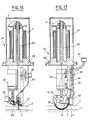
- Figures 13 and 14 show in elevation, in two perpendicular directions and with partial section, a device according to the invention produced in the form of a stitching head.
- FIG. 15 shows, in perspective, a stitching machine incorporating the head of FIGS. 13 and 14.
- FIG. 16 illustrates the formation of a final composite part, by machining a raw part, obtained by impregnation with a curable binder of a reinforcing element produced according to the invention.
- FIG. 1 shows a support 1 on which a substrate 2 of resistant fibers rests, as well as a stitching needle 3.1, intended to introduce a fiber 4 inside said substrate 2.
- the support 1 can be made of any desired material, such as metallic and possibly be covered with a coating (not shown), for example made of polytetrafluoroethylene. However, it can also be made of foam material, as is known in the art. Depending on the shape of the reinforcement element to be obtained, it can be constituted by a simple plate (which is represented in FIG. 1) or else by a mandrel having a shape of revolution and intended to be driven in rotation during the stitching operation (figure 15).
- the resistant fiber substrate 2 can be of the two-dimensional type, consisting of fibers crossed in at least two directions.
- the fiber 4 is intended to form the third dimension of said substrate.
- the substrate 2 can also be of the three-dimensional type and then the fiber 4 is intended to form a reinforcement for the third dimension.
- the substrate 2 can be formed on the support 1 or else be produced and brought to said support to receive the curved stitching operations there.
- the resistant fibers constituting the substrate 2 and the fiber 4 can be of different known types, such as glass, carbon, boron, KEVLAR (registered trademark), etc.
- the needle 3.1 has a circular shape, with a center 5. It is hollow and is traversed by an internal channel 6, emerging through a lateral eye 7, adjacent to the tip 8 of said needle and arranged in the concavity thereof. On the side opposite to the point 8, the internal channel 6 opens out through an orifice 9.
- the internal channel 6 is intended to be crossed by the fiber 4, entering through the orifice 9 and leaving through the lateral eye 7.
- the internal channel 6 comprises a rounded flare 10 at the level of the orifice 9, while an internal rounded bead 11 is provided on the edge of the eye 7, opposite the point 8.
- the end of the needle 3.1, opposite the point 8, is fixed in a needle holder 12, capable of being animated (see the double arrow F) with a back-and-forth movement in rotation around d 'an axis 13-13, passing through the center 5 of the needle 3.1 and at least substantially perpendicular to the plane thereof. Furthermore, a relative movement of movement is generated between the assembly of the support 1 and the substrate 2, on the one hand, and the needle 3.1, on the other hand.
- said needle 3.1 introduces into substrate 2 a curved segment 4b of said fiber 4, segment 4b of a pair of segments 4a, 4b being connected to the segment 4a of the pair of segments 4a, 4b following by a bridge 4c, parallel to the axis 13-13, forming during the relative displacement f1, while, on the side opposite to the bridges 4c, the two segments 4a and 4b d 'the same pair are connected to each other by a 4d loop.
- FIGS. 3a1, 2b1 and 3c1 which correspond to schematic views along the line III-III in FIG. 1 and on which, for clarity purposes, the segments 4a and 4b have been offset in the thickness direction of the substrate 2.
- FIG. 3a1 a stitching configuration has been shown for which the segments 4a and 4b are tangent to the face 1a of the support 1 on which the substrate 2 rests and the loops 4d appear outside the free face 2a of said substrate, through which the needle 3.1 penetrates.
- Such a stitching configuration is advantageous when a support 1 is used in which the needle 3.1 cannot penetrate (metal support for example) and it is desired that the segments 4a and 4b constitute a reinforcement over the entire thickness of said substrate 2.
- the support 1 was made of a material capable of being easily penetrated by the needle 3.1, the segments 4a and 4b could pass through at least the surface layer of said support. This is in particular advantageous when the support 1 is made of a material which, moreover, is destructible after production of the reinforcing element.
- the loops 4d are also external to the substrate 2, on the side of the free face 2a thereof, but the segments 4a and 4b do not penetrate into said substrate up to the face 1a of the support 1.
- the segments 4a and 4b can constitute a surface reinforcement of the substrate 2.
- the loops 4d are formed inside the substrate 2, for example at the level of the free face 1a of the support 1, and are retained by the pressure and the friction exerted by the substrate material 2.
- FIG. 3d1 it is assumed to have carried out a first stitching operation similar to that of FIG. 3c1, then a second similar operation, symmetrical with the first with respect to the plane passing through the axis 13-13 and orthogonal to support 1.
- FIGS. 3a2 to 3d2 corresponds to Figure 3a1 to 3d1, of index a, b, c or d identical.
- the bridges 4c instead of being perpendicular to the plane of the drawings as in FIGS. 3a1 to 3d1 (the pairs of adjacent segments 4a, 4b being thus superimposed), are on the contrary parallel to the plane of FIGS. 3a2 to 3d2 , so that they are visible thereon and that several pairs of consecutive curved segments 4a, 4b are also visible.
- the relative movement of the needle 3.1 relative to the support 1 does not necessarily take place in one of the directions f1 or f2. Such relative displacement could take place in any other direction, for example at 45 ° relative to f1 and f2.
- this relative displacement is not necessarily linear and that it can follow a curved trajectory, such as circular, helical, spiral, etc. or even a combination of such trajectories.
- FIG. 4,5 and 6 there is illustrated a first alternative embodiment 3.2 of the needle 3.1.
- the needle 3.2 is also circular, from the center 5. However, instead of being hollow, it is full and it has a thread guide groove 14 along its convexity. On the side of its point 8, it has an eye 15 facing its concavity and in communication, through a passage 16, with said groove 14. It is easily understood that the needle 3.2 operates in a similar fashion to the needle 3.1, the fiber 4 being guided by the groove 14, as far as the eye 15 (see FIG. 4), instead of being guided by the internal channel 6.
- the second alternative embodiment 3.3 of the needle 3.1 shown in FIG. 7, is circular, of center 5. On the side of its tip 8, it comprises a hook 17 turned towards its concavity and which can be closed by a valve formed by the end of a circular rod 18, which can slide inside a channel 19 provided in said needle, under the action of a translational control device 20.
- the needle 3.3 operates somewhat differently that of needles 3.1 and 3.2.
- the valve of the needle 3.3 being closed, said needle is caused to cross, during its forward movement, the substrate 2 and to come out through the free face thereof.
- the valve opens and the hook 17 grasps the fiber 4, supplied by an auxiliary device 21, after which said valve closes and the needle 3.3 pulls the fiber 4 through said substrate during its withdrawal, simultaneously forming the segments 4a and 4b of a pair of segments, said fiber being gripped by the hook 17 at the level of a loop 4d.
- the needle 3.3 projects said loop 4d, after which a new cycle can start again. In this way, a loop being formed is passed through the previously made loop, so that the 4d loops are linked together by a chain stitch.
- the needle 3.3 requires the crossing of the free face 2a of the substrate 2 at the end of the forward movement of said needle, so that it cannot carry out the stitching configurations illustrated by FIGS. 3c1, 3d1, 3c2 and 3d2.
- valve needle operating in a manner analogous to the needle 3.3.
- the valve 22 is rotary and automatic, opening in the forward movements of the needle under the thrust of the loop 4d which has just been formed, and coming to be partially housed in a housing 23 provided in the concavity of said needle.
- the valve is tilted to the closed position of the hook 17 under the pressure of the material of the substrate 2.
- FIG 9 there is shown in front view, by completing it, the device of Figure 1.
- an arm 30, which is secured to displacement means not shown of a machine for be able to move relative to the support 1 and which carries, at its end facing said support 1, the needle holder 12 mounted articulated around the axis 13-13, by means of a hinge 31.
- a thread clamp 32 is mounted on the needle holder 12, on the side of the orifice 9 of the needle 3.1, opposite the tip 8.
- this wire clamp comprises a fixed part 32a and a movable part 32b, controllable so as to be able to move away from or closer to said part 32a, it that is to say that the fiber 4, which passes between the fixed and mobile parts 32a and 32b, can be free to pass between them or on the contrary be pinched between them.
- FIG. 10 illustrates an operating mode of the device of FIG. 9, mainly used for thin substrates 2.
- the needle 3.1 undergoes, the thread clamp 32 being open, a return rotation around the axis 13-13 of amplitude A sufficient for the length 33 of fiber 4 leaving the needle and between the eye 7 and the substrate 2 corresponds to the sum of the lengths of the bridge 4c, the curved segment 4a and the loop 4d.
- the bridge 4c and the curved segment 4a After having closed the wire clamp 32, it is therefore possible to make the bridge 4c and the curved segment 4a by rotating the needle 3.1 around its axis 13-13, from this return position, in the direction of the substrate 2.
- the thread clamp 32 is opened before the needle begins its withdrawal stroke.
- the curved segment 4b is formed, for example by virtue of the friction exerted by the substrate 2 on the fiber 4.
- this friction is not sufficient, use a member for retaining the loop 4d.
- the arm 30 is moved orthogonally to the support 1.
- the axis 13-13 can be passed from a first position 13.1 brought close to a position 13.2 distant from the support 1, then to a second close position 13.3. So in this movement of alienation and closeness from the axis 13-13 of the substrate 2, associated with the return stroke of the needle 3.1 around said axis 13.13, it is possible to obtain a displacement amplitude B sufficient to release the clamp at the exit of said needle -wire 32 being open, a length 34 of fiber 4 corresponding to the sum of lengths of the bridge 4c, of the segment 4a and of the loop 4d. This length of fiber 34 is stitched into the substrate 2, when the axis 13-13 occupies its close position 13.3.
- FIG. 12a illustrate yet another mode of operation.
- the needle 21 has just been displaced by the pitch p , corresponding to the bridge 4c, and an adequate length 35 of fiber 4 is available at the outlet of the needle 3.1.
- the wire clamp 32 is closed.
- the stitching operation begins by rotating the needle 3.1 ( Figure 12b) and continues until, after insertion of the segment 4a, the loop 4d appears on the face 2a ( Figure 12c).
- a retaining member 36 grips the loop 4d.
- the thread clamp 32 opens and the needle 3.1 performs its return-to-rotation stroke by forming the segment 4b (FIG. 12d). At the end of the return stroke (FIG.
- a member 37 comes to grip the fiber 4 at the outlet of the needle 3.1 to form the length 35.
- the thread clamp 32 closes and the members 36 and 37 are retracted and the device (see FIG. 12f) is ready to move from step p to take the position illustrated in FIG. 12a. Another stitching cycle can begin.
- FIG. 13 and 14 illustrate an embodiment of a stitching head 40 according to the invention.
- the arm 30 supports a reserve 41 of fiber 4 which is brought to the needle 3 through a guide 42.
- the arm 30 also carries a motor 43 for actuating the needle 3 in rotation about the axis 13.13 , a member 44 for actuating the loop retaining member 36 and a member 46 for actuating the fiber gripping member 37.
- the various motors and members 43 to 46 are connected to control devices (not shown) by a connector 47.
- the stitching head 40 has a flange 48 for its attachment to a stitching machine such as that shown in FIG. 15.
- the machine 50 shown in FIG. 15, comprises an arm 51 which can be moved in three dimensions X, Y and Z, relative to a frame 52.
- the arm 51 can be moved vertically in Z, relative to a carriage 53, thanks to a motor 54, while the carriage 53 is mounted mobile in Y on a beam 55 thanks to a motor 56 and that said beam 55 is itself mounted mobile in X, relative to the frame 52, thanks to a motor 57.
- the stitching head 40 is mounted at the lower end of the arm 51 so that it can be rotatable around each of the axes X, Y and Z.
- the support 1, illustrated in FIG. 15 under the shape of a rotary mandrel, carries the substrate 2.
- a control station 58 makes it possible to control the movement of the head 40 relative to the substrate 2 and the various operations of stitching the needle 3 into the substrate.
- the support 1 can have any desired shape and the direction of the stitching lines, both relative to the support 1 and relative to the plane of the needle 3, can be chosen according to the purpose to be obtained.
- the stitching depth in the substrate 2 can be straight, curved, circular, helical, etc.
Landscapes
- Engineering & Computer Science (AREA)
- Textile Engineering (AREA)
- Mechanical Engineering (AREA)
- Chemical & Material Sciences (AREA)
- Composite Materials (AREA)
- Nonwoven Fabrics (AREA)
- Sewing Machines And Sewing (AREA)
- Laminated Bodies (AREA)
- Yarns And Mechanical Finishing Of Yarns Or Ropes (AREA)
- Chemical Or Physical Treatment Of Fibers (AREA)
- Multicomponent Fibers (AREA)
- Moulding By Coating Moulds (AREA)
- Reinforced Plastic Materials (AREA)
- Inorganic Fibers (AREA)
Claims (32)
- Verfahren zur Verwirklichung von Armierungselementen mit dreidimensional verteilten widerstandsfähigen Fasern, nach dem in ein Substrat (2) auf einer Unterlage (1), das aus derartigen in wenigstens zwei Richtungen gekreuzten Fasern besteht, von der freien Seite (2a) des Substrats aus, die der Unterlage entgegengesetzt ist, mit Hilfe einer Nadel (3.1 bis 3.4), der eine Hin- und Herbewegung aufgegeben wird, eine Endlosfaser (4) eingesteppt wird, wobei außerdem eine relative Verschiebung zwischen der Unterlage und der Nadel erzeugt wird, so daß die Endlosfaser innerhalb des Substrats aus einer Folge aufeinanderfolgender, eine gebrochene Linie bildender Segmente (4a,4b) besteht,
dadurch gekennzeichnet, daß- die Nadel (3.1 bis 3.4) gebogen ist und jedem Segment (4a,4b) der Endlosfaser (4) eine ähnliche gebogene Form verleiht, und- die Hin- und Herbewegung der gebogenen Nadel unter Drehung um eine Achse (13-13) senkrecht zur Ebene der Nadel auf der konkaven Seite derselben erfolgt. - Verfahren nach Anspruch 1,
dadurch gekennzeichnet, daß die gebogene Nadel (3.1 bis 3.4) eine runde Form hat, und dadurch, daß die Drehachse (13-13) koaxial zur Nadel verläuft. - Verfahren nach einem der Ansprüche 1 oder 2,
dadurch gekennzeichnet, daß die gebogene Nadel (3.1,3.2,3.3,3.4) während ihrer Hin- und Herbewegung die Seite (1a) der Unterlage (1) berührt, auf der sich das Substrat (2) befindet. - Verfahren nach einen der Ansprüche 1 oder 2,
dadurch gekennzeichnet, daß die gebogene Nadel (3.1,3.2,3.3,3.4) während ihrer Hin- und Herbewegung zu Seite (1a) der Unterlage (1), auf der sich das Sustrat (2) befindet, in Abstand verbleibt. - Verfahren nach einem der Ansprüche 1 bis 4,
dadurch gekennzeichnet, daß am Ende der Hinbewegung und zu Beginn der Rückbewegung der gebogenen Nadel (3.1,3.2,3.3,3.4) die Spitze (8) derselben über der freien Seite (2a) des Substrats übersteht. - Verfahren nach einem der Ansprüche 1 bis 4,
dadurch gekennzeichnet, daß am Ende der Hinbewegung und zu Beginn der Rückbewegung der Nadel (3.1,3.2) die Spitze (8) derselben in das Substrat (2) eingestochen ist. - Verfahren nach einem der Ansprüche 1 bis 6,
dadurch gekennzeichnet, daß die relative Verschiebung zwischen der Unterlage (1) und der Nadel geradlinig ist. - Verfahren nach einem der Ansprüche 1 bis 6,
dadurch gekennzeichnet, daß die relative Verschiebung zwischen der Unterlage (1) und der Nadel bogenförmig ist. - Verfahren nach einem der Ansprüche 7 oder 8,
dadurch gekennzeichnet, daß die relative Verschiebung zwischen der Unterlage (1) und der Nadel parallel zur Ebene der Nadel erfolgt. - Verfahren nach einem der Ansprüche 7 oder 8,
dadurch gekennzeichnet, daß die relative Verschiebung zwischen der Unterlage und der Nadel senkrecht zur Ebene der Nadel erfolgt. - Verfahren nach einem der Ansprüche 7 oder 8,
dadurch gekennzeichnet, daß die relative Verschiebung zwischen der Unterlage und der Nadel um einen von 90° unterschiedlichen Winkel gegenüber der Ebene der Nadel geneigt ist. - Verfahren nach einem der Ansprüche 1 bis 11,
dadurch gekennzeichnet, daß die relative Verschiebung zwischen der Unterlage und der Nadel so erfolgt, daß die Drehachse (13-13) der Nadel in einem konstanten Abstand zur Unterlage (1) verbleibt. - Verfahren nach einem der Ansprüche 1 bis 11,
dadurch gekennzeichnet, daß die Drehachse (13-13) der Nadel bei der relativen Verschiebung zwischen der Unterlage und der Nadel von der Unterlage abgestellt und an diese angestellt werden kann. - Vorrichtung zur Verwirklichung von Armierungselementen mit dreidimensional verteilten widerstandsfähigen Fasern, die umfaßt:. eine Unterlage (1), auf der sich ein Substrat (2) aus solchen in wenigstens zwei Richtungen gekreuzten Fasern befindet;. eine Nadel (3.1 bis 3.4), mit der in das Substrat von dessen freier, der Unterlage entgegengesetzten Seite (2a) aus eine Endlosfaser (4) eingeführt werden kann;. Mittel, um der Nadel eine Hin- und Herbewegung aufzugeben, und. Mittel zur Erzeugung einer relativen Verschiebung der Unterlage gegenüber der Nadel,
dadurch gekennzeichnet, daß- die Nadel (3.1 bis 3.4) gebogen ist und zur Führung der Endlosfaser (4) innerhalb des Substrats (2) dient, und- Mittel (12,43) vorgesehen sind, durch die die Nadel in einer hin- und hergehenden Drehbewegung um eine Achse (13-13) gesteuert werden kann, die senkrecht zur Ebene der Nadel auf deren konkaver Seite verläuft. - Vorrichtung nach Anspruch 14,
dadurch gekennzeichnet, daß die gebogene Nadel eine runde Form hat, und dadurch, daß die Drehachse (13-13) koaxial zur Nadel verläuft. - Vorrichtung nach einem der Ansprüche 14 oder 15,
dadurch gekennzeichnet, daß die gebogene Nadel (3.1) zur Führung der Faser einen Innenkanl (6) hat, der in der Nähe der Spitze (8) der Nadel in einem seitlichen Öhr (7) mündet. - Vorrichtung nach Anspruch 16,
dadurch gekennzeichnet, daß sich das seitliche Öhr (7) in der Vertiefung der Nadel (3.1) befindet. - Vorrichtung nach einem der Ansprüche 14 oder 15,
dadurch gekennzeichnet, daß die gebogene Nadel (3.2) entlang ihrer Vertiefung eine Fadenführungsrille (14) und in ihrer Vertiefung in der Nähe ihrer Spitze (8) ein seitliches Öhr hat, wobei das Öhr (15) mit der Rille (14) über einen Durchgang (16) in Verbindung steht. - Vorrichtung nach einem der Ansprüche 14 oder 15,
dadurch gekennzeichnet, daß die gebogene Nadel (3.3,3.4) in der Nähe ihrer Spitze (8) einen nach ihrer Vertiefung gerichteten Haken (17) hat, der durch eine Klappe (18,22) verschlossen werden kann. - Vorrichtung nach Anspruch 19,
dadurch gekennzeichnet, daß die Klappe durch eine Vorrichtung (20) gesteuert wird. - Vorrichtung nach Anspruch 19,
dadurch gekennzeichnet, daß die Klappe automatisch durch die Faser und durch das Substrat gesteuert wird. - Vorrichtung nach einem der Ansprüche 14 bis 21,
dadurch gekennzeichnet, daß die Nadel (3.1 bis 3.4) in einem Nadelhalter (12) angeordnet ist, der um die Drehachse (13-13) der Nadel gelenkig an einem Arm (30) angebracht ist, der gegenüber der Unterlage (1) verschiebbar ist. - Vorrichtung nach Anspruch 22,
dadurch gekennzeichnet, daß am Nadelhalter (12) eine steuerbare Fadenklemme angebracht ist. - Vorrichtung nach einem der Ansprüche 22 oder 23,
dadurch gekennzeichnet, daß der Arm (30) eine Faserreserve (41) für die Nadel hat. - Vorrichtung nach einem der Ansprüche 22 bis 24,
dadurch gekennzeichnet, daß der Arm (30) einen Mechanismus (37,46) hat, mit dem die Faser (4) am Ausgang der Nadel (3.1 bis 3.4) zwischen jedem Steppstich abgezogen werden kann. - Vorrichtung nach einem der Ansprüche 22 bis 25, dadurch gekennzeichnet, daß der Arm (30) einen Mechanismus (36,45) zur Bildung einer Schlinge (4d) hat, wenn die Spitze (8) der Nadel, nachdem sie in das Substrat (2) eingedrungen ist, dessen freie Seite (2a) verläßt.
- Vorrichtung nach einem der Ansprüche 22 bis 26, dadurch gekennzeichnet, daß der Arm (30) mit einer Maschine (50) verbunden ist, durch die er gegenüber der Unterlage (1) verschoben werden kann.
- Vorrichtung nach einem der Ansprüche 14 bis 27,
dadurch gekennzeichnet, daß die Unterlage (1) feststehend ist. - Vorrichtung nach einem der Ansprüche 14 bis 27,
dadurch gekennzeichnet, daß die Unterlage (1) aus einem Drehdorn besteht. - Armierungselement mit dreidimensional verteilten widerstandsfähigen Fasern, wobei das Armierungselement ein Substrat (2) aus solchen in wenigstens zwei Richtungen gekreuzten Fasern hat, dadurch gekennzeichnet, daß es gebogene Fasersegmente (4a,4b) hat, die in der Dicke des Substrats (2) angeordnet sind, wobei diese gebogenen Fasersegmente zu ein und derselben Endlosfaser gehören.
- Verbundteil mit einem Armierungselement aus dreidimensional verteilten widerstandsfähigen Fasern, die mit einem gehärteten Bindemittel getränkt wurden, wobei das Armierungselement ein Substrat (2) aus solchen in wenigstens zwei Richtungen gekreuzten Fasern hat,
dadurch gekennzeichnet, daß gebogene Fasersegmente (4a,4b) in der Dicke des Substrats (2) angeordnet sind, wobei diese gebogenen Fasersegmente zu ein und derselben Endlosfaser gehören. - Verbundteil nach Anspruch 31,
dadurch gekennzeichnet, daß es wenigstens an der Oberfläche bearbeitet ist.
Applications Claiming Priority (2)
| Application Number | Priority Date | Filing Date | Title |
|---|---|---|---|
| FR9002352A FR2658841B1 (fr) | 1990-02-26 | 1990-02-26 | Procede et dispositif pour la realisation d'elements d'armature composes de fibres resistantes. |
| FR9002352 | 1990-02-26 |
Publications (2)
| Publication Number | Publication Date |
|---|---|
| EP0444971A1 EP0444971A1 (de) | 1991-09-04 |
| EP0444971B1 true EP0444971B1 (de) | 1995-01-04 |
Family
ID=9394127
Family Applications (1)
| Application Number | Title | Priority Date | Filing Date |
|---|---|---|---|
| EP91400129A Expired - Lifetime EP0444971B1 (de) | 1990-02-26 | 1991-01-21 | Verfahren und Vorrichtung zur Verbundelement-Herstellung aus widerstandsfähigen Fasern |
Country Status (10)
| Country | Link |
|---|---|
| US (2) | US5095833A (de) |
| EP (1) | EP0444971B1 (de) |
| JP (1) | JP2891788B2 (de) |
| AT (1) | ATE116699T1 (de) |
| CA (1) | CA2036985A1 (de) |
| DE (1) | DE69106404T2 (de) |
| ES (1) | ES2069228T3 (de) |
| FR (1) | FR2658841B1 (de) |
| IE (1) | IE61078B1 (de) |
| NO (1) | NO176930C (de) |
Cited By (1)
| Publication number | Priority date | Publication date | Assignee | Title |
|---|---|---|---|---|
| RU208322U1 (ru) * | 2021-07-08 | 2021-12-14 | федеральное государственное бюджетное образовательное учреждение высшего образования «Белгородский государственный технологический университет им. В.Г. Шухова» | Машина для сшивания полотнищ |
Families Citing this family (38)
| Publication number | Priority date | Publication date | Assignee | Title |
|---|---|---|---|---|
| FR2687174B1 (fr) * | 1992-02-11 | 1995-09-22 | Aerospatiale | Procede pour la realisation d'une armature de fibres pour piece de matiere composite a parois non coplanaires, et piece composite comportant une telle armature. |
| FR2687173B1 (fr) * | 1992-02-11 | 1995-09-08 | Aerospatiale | Procede pour la realisation d'une armature de fibres pour piece de matiere composite, et piece composite comportant une telle armature. |
| JPH0675624B2 (ja) * | 1992-05-22 | 1994-09-28 | 菅原ミシン株式会社 | 掬い縫いミシンの針運動機構 |
| IL105788A (en) * | 1992-06-01 | 1996-10-16 | Allied Signal Inc | Tailor-made composite structures with improved penetration resistance |
| GB9406537D0 (en) * | 1994-03-31 | 1994-05-25 | British Aerospace | Blind stitching apparatus and composite material manufacturing methods |
| US6001968A (en) | 1994-08-17 | 1999-12-14 | The Rockefeller University | OB polypeptides, modified forms and compositions |
| DE19629044C2 (de) * | 1995-07-19 | 1998-12-03 | Deutsch Zentr Luft & Raumfahrt | Flächige Struktur aus Faserverbundwerkstoffen und Verfahren zu ihrer Herstellung |
| DE19813887A1 (de) * | 1998-03-28 | 1999-09-30 | Freundes Und Foerderkreis Des | Verfahren und Vorrichtung zur Herstellung von Nähnähten |
| FR2779749B1 (fr) * | 1998-06-10 | 2000-08-11 | Aerospatiale | Armature fibreuse pour piece de matiere composite, ainsi que procede et dispositif pour sa realisation |
| US6196145B1 (en) * | 1998-11-17 | 2001-03-06 | Albany International Techniweave, Inc. | Yarn insertion mechanism |
| DE10040807B4 (de) * | 2000-08-21 | 2004-07-15 | Ksl Keilmann Sondermaschinenbau Gmbh | Blindstichnähvorrichtung |
| US6467149B2 (en) * | 2000-12-07 | 2002-10-22 | The Goodyear Tire & Rubber Company | Apparatus for injecting materials into a composite |
| US7056576B2 (en) * | 2001-04-06 | 2006-06-06 | Ebert Composites, Inc. | 3D fiber elements with high moment of inertia characteristics in composite sandwich laminates |
| US7731046B2 (en) * | 2001-04-06 | 2010-06-08 | Ebert Composites Corporation | Composite sandwich panel and method of making same |
| US20050025948A1 (en) * | 2001-04-06 | 2005-02-03 | Johnson David W. | Composite laminate reinforced with curvilinear 3-D fiber and method of making the same |
| US7105071B2 (en) | 2001-04-06 | 2006-09-12 | Ebert Composites Corporation | Method of inserting z-axis reinforcing fibers into a composite laminate |
| US7785693B2 (en) | 2001-04-06 | 2010-08-31 | Ebert Composites Corporation | Composite laminate structure |
| US6676785B2 (en) | 2001-04-06 | 2004-01-13 | Ebert Composites Corporation | Method of clinching the top and bottom ends of Z-axis fibers into the respective top and bottom surfaces of a composite laminate |
| US6645333B2 (en) | 2001-04-06 | 2003-11-11 | Ebert Composites Corporation | Method of inserting z-axis reinforcing fibers into a composite laminate |
| US20050118448A1 (en) * | 2002-12-05 | 2005-06-02 | Olin Corporation, A Corporation Of The Commonwealth Of Virginia | Laser ablation resistant copper foil |
| DE102005034400B4 (de) | 2005-07-22 | 2010-09-23 | Airbus Deutschland Gmbh | Vorrichtung zur Herstellung eines Faservorformlings mit einer nahezu beliebigen Oberflächengeometrie im TFP-Verfahren |
| DE102005034393B4 (de) * | 2005-07-22 | 2009-04-02 | Airbus Deutschland Gmbh | Verfahren zur Herstellung von ein- oder mehrschichtigen Faservorformlingen im TFP-Verfahren |
| US7854208B1 (en) * | 2007-05-14 | 2010-12-21 | Martelli John D | Unibody support apparatus and method |
| FR2941710B1 (fr) * | 2009-02-05 | 2011-03-18 | Airbus France | Procede d'assemblage par couture d'elements fibreux et dispositif pour sa mise en oeuvre. |
| JP5295899B2 (ja) * | 2009-07-29 | 2013-09-18 | 日機装株式会社 | 繊維強化樹脂複合材料の製造方法 |
| DE102010050740B4 (de) * | 2010-11-08 | 2012-12-06 | Airbus Operations Gmbh | Verfahren und Vorrichtung zur Herstellung eines Flugzeugstrukturbauteils |
| US20130315747A1 (en) * | 2012-05-23 | 2013-11-28 | Karsten Schibsbye | Wind turbine blade with improved geometry for reinforcing fibers |
| DE102015110855B4 (de) * | 2015-07-06 | 2019-12-05 | Technische Universität Chemnitz | Verfahren zur Fertigung von komplexen 3D-Preformen |
| FR3062810A1 (fr) * | 2017-02-13 | 2018-08-17 | Airbus Operations | Procede et systeme de fixation par piquage en zigzag d'un element souple fonctionnel sur un support souple. |
| US10624738B2 (en) | 2017-02-23 | 2020-04-21 | Edwards Lifesciences Corporation | Heart valve manufacturing devices and methods |
| IL275709B2 (en) * | 2018-01-12 | 2025-06-01 | Edwards Lifesciences Corp | Automated heart valve sewing |
| MX2021001673A (es) | 2018-08-22 | 2021-04-19 | Edwards Lifesciences Corp | Dispositivos y metodos automatizados de manufactura de valvulas cardiacas. |
| DE102020202270A1 (de) * | 2020-02-21 | 2021-08-26 | Pfaff Industriesysteme Und Maschinen Gmbh | Nähmaschine |
| WO2021251954A1 (en) | 2020-06-09 | 2021-12-16 | Edwards Lifesciences Corporation | Automated sewing and thread management |
| RU2763580C1 (ru) * | 2021-07-08 | 2021-12-30 | федеральное государственное бюджетное образовательное учреждение высшего образования «Белгородский государственный технологический университет им. В.Г. Шухова» | Машина для сшивания полотнищ |
| US12428764B2 (en) * | 2023-05-12 | 2025-09-30 | Rohr, Inc. | Systems and methods for non-linear through thickness reinforcement |
| US12297573B2 (en) | 2023-05-12 | 2025-05-13 | Rohr, Inc. | Systems and methods for through thickness reinforcement using roll-to-roll veil cloth |
| CN118372487A (zh) * | 2024-05-27 | 2024-07-23 | 浙江航引新材料科技有限公司 | 一种加强筋复合材料用自动缝合装置 |
Family Cites Families (12)
| Publication number | Priority date | Publication date | Assignee | Title |
|---|---|---|---|---|
| DE411024C (de) * | 1925-03-23 | Masch Werke Zu Frankfurt A M V | Gebogene Naehnadel mit seitlichem, hakenfoermigem OEhr fuer Schuhwerk-Naehmaschinen | |
| DE288794C (de) * | ||||
| FR478025A (fr) * | 1913-10-03 | 1915-11-19 | Mark Thomas Denne | Machine à coudre à aiguille et alène courbes |
| US1909434A (en) * | 1930-02-21 | 1933-05-16 | United Mattress Machinery Comp | Side stitching a mattress |
| US3322868A (en) * | 1963-07-02 | 1967-05-30 | Douglas Aircraft Co Inc | Three dimensional reinforced structure |
| US3340586A (en) * | 1965-08-30 | 1967-09-12 | Singer Co | Methods and apparatus for needling textile fibers |
| FR1490415A (fr) * | 1965-08-30 | 1967-07-28 | Singer Co | Procédé et appareil pour aiguilleter des fibres textiles |
| US3950587A (en) * | 1971-01-12 | 1976-04-13 | Breveteam, S.A. | Non-woven textile fiber products having a relief-like structure |
| GB1328972A (en) * | 1971-04-19 | 1973-09-05 | Ethicon Inc | Needled suture |
| FR2315562A1 (fr) * | 1975-06-26 | 1977-01-21 | Commissariat Energie Atomique | Procede et dispositifs de fabrication de corps ou pieces en tissus tri-dimensionnels |
| US4506611A (en) * | 1979-10-22 | 1985-03-26 | Hitco | Three-dimensional thick fabrics and methods and apparatus for making same |
| FR2612950B1 (fr) * | 1987-03-25 | 1989-06-09 | Aerospatiale | Procede de fabrication d'elements d'armature composites tisses en trois dimensions, machine pour sa mise en oeuvre et produit obtenu |
-
1990
- 1990-02-26 FR FR9002352A patent/FR2658841B1/fr not_active Expired - Fee Related
-
1991
- 1991-01-21 ES ES91400129T patent/ES2069228T3/es not_active Expired - Lifetime
- 1991-01-21 DE DE69106404T patent/DE69106404T2/de not_active Expired - Fee Related
- 1991-01-21 AT AT91400129T patent/ATE116699T1/de not_active IP Right Cessation
- 1991-01-21 EP EP91400129A patent/EP0444971B1/de not_active Expired - Lifetime
- 1991-01-25 US US07/646,094 patent/US5095833A/en not_active Expired - Fee Related
- 1991-01-29 IE IE30691A patent/IE61078B1/en not_active IP Right Cessation
- 1991-02-25 NO NO910737A patent/NO176930C/no unknown
- 1991-02-25 CA CA002036985A patent/CA2036985A1/fr not_active Withdrawn
- 1991-02-26 JP JP3053120A patent/JP2891788B2/ja not_active Expired - Lifetime
-
1993
- 1993-04-14 US US08/048,080 patent/US5350615A/en not_active Expired - Fee Related
Cited By (1)
| Publication number | Priority date | Publication date | Assignee | Title |
|---|---|---|---|---|
| RU208322U1 (ru) * | 2021-07-08 | 2021-12-14 | федеральное государственное бюджетное образовательное учреждение высшего образования «Белгородский государственный технологический университет им. В.Г. Шухова» | Машина для сшивания полотнищ |
Also Published As
| Publication number | Publication date |
|---|---|
| JP2891788B2 (ja) | 1999-05-17 |
| NO910737L (no) | 1991-08-27 |
| CA2036985A1 (fr) | 1991-08-27 |
| NO176930B (no) | 1995-03-13 |
| ES2069228T3 (es) | 1995-05-01 |
| IE910306A1 (en) | 1991-08-28 |
| DE69106404T2 (de) | 1995-05-04 |
| US5095833A (en) | 1992-03-17 |
| FR2658841B1 (fr) | 1993-06-11 |
| FR2658841A1 (fr) | 1991-08-30 |
| DE69106404D1 (de) | 1995-02-16 |
| JPH0610257A (ja) | 1994-01-18 |
| ATE116699T1 (de) | 1995-01-15 |
| NO910737D0 (no) | 1991-02-25 |
| EP0444971A1 (de) | 1991-09-04 |
| US5350615A (en) | 1994-09-27 |
| IE61078B1 (en) | 1994-09-21 |
| NO176930C (no) | 1995-06-21 |
Similar Documents
| Publication | Publication Date | Title |
|---|---|---|
| EP0444971B1 (de) | Verfahren und Vorrichtung zur Verbundelement-Herstellung aus widerstandsfähigen Fasern | |
| EP0556088B1 (de) | Verfahren zur Herstellung eine Fasernverstärkung für ein Teil aus Verbundmaterial und Verbundteil aus einer solchen Verstärkung | |
| CA1319081C (fr) | Machine pour la mise en oeuvre d'un procede de fabrication d'elements d'armature composites tisses en trois dimensions, et produit obtenu | |
| CA1044882A (fr) | Procede et dispositifs de fabrication de corps ou pieces en tissus tridimensionnels | |
| EP0678609A1 (de) | Verfahren und Vorrichtung zur Herstellung einer Verstärkung für einen Teil Verbundmaterial | |
| FR2687389A1 (fr) | Dispositif et procede pour realiser une piece de structure complexe par depose au contact de fil ou ruban. | |
| EP0833972B1 (de) | Verfahren und vorrichtung zur herstellung von ringförmigen werkstücken aus verbundmaterial und vorformlinge für diese werkstücke | |
| EP0556089B1 (de) | Verfahren zur Herstellung einer Faserverstärkung für ein Teil aus Verbundmaterial mit nicht-koplanaren Seiten und Verbundteile mit einer solchen Verstärkung | |
| EP0678611A1 (de) | Nadelkopf und Vorrichtung zur Herstellung einer Verstärkungsplatte für einen Teil Verbundmaterial | |
| EP0678610A1 (de) | Verfahren und Vorrichtung zur Herstellung einer Verstärkungsplatte für einen Teil Verbundmaterial | |
| EP0310499A1 (de) | Verfahren und Vorrichtung zur Herstellung eines Faserschichtkörpers, verwendbar als Verstärkungsstruktur für ein aus mehreren Bestandteilen zusammengesetztes | |
| EP0553000A1 (de) | Nähverfahren für ein Faserteil | |
| FR2941710A1 (fr) | Procede d'assemblage par couture d'elements fibreux et dispositif pour sa mise en oeuvre. | |
| EP0536029B1 (de) | Verfahren und Maschine zur Herstellung von gewebten faserförmigen Armierungen | |
| EP0965440A1 (de) | Faserförmige Bewehrung für ein Teil aus Verbundwerkstoff sowie Verfahren und Vorrichtung zu dessen Herstellung | |
| CA2125010A1 (fr) | Dispositif de liaison mecanique en resine renforcee de fibres bobinees procede de fabrication | |
| EP0387129B1 (de) | Nadel zur Durchführung von Vorgängen mit Faden, Strähnen und biegeweichen Schnüren sowie Vorrichtung zur Verwendung einer solchen Nadel | |
| EP0046119B1 (de) | Nadel mit einem Öhr, welches geöffnet werden kann | |
| EP4015686B1 (de) | Fachbildungsmechanismus und webmaschine vom typ jacquardwebmaschine, die mit einem solchen mechanismus ausgestattet ist | |
| FR2941711A1 (fr) | Crochet pour l'assemblage par couture d'elements fibreux | |
| CA2411710A1 (fr) | Procede de realisation d'une preforme textile multidirectionnelle, dispositif pour sa mise en oeuvre et preforme ainsi obtenue | |
| BE1003829A6 (fr) | Procede et dispositif de fabrication d'un tapis a points noues. | |
| FR2660673A1 (fr) | Procede de realisation de preformes au moyen d'une texture tissee et bobinee, pour la fabrication de pieces en materiau composite. | |
| CA1323287C (fr) | Element d'armature composite tisse en trois dimensions | |
| FR3098444A1 (fr) | Procédé de renforcement d’un panneau et un procédé de fabrication de panneau composite mettant en œuvre un tel procédé |
Legal Events
| Date | Code | Title | Description |
|---|---|---|---|
| PUAI | Public reference made under article 153(3) epc to a published international application that has entered the european phase |
Free format text: ORIGINAL CODE: 0009012 |
|
| AK | Designated contracting states |
Kind code of ref document: A1 Designated state(s): AT BE CH DE DK ES GB IT LI NL SE |
|
| 17P | Request for examination filed |
Effective date: 19911029 |
|
| 17Q | First examination report despatched |
Effective date: 19930903 |
|
| GRAA | (expected) grant |
Free format text: ORIGINAL CODE: 0009210 |
|
| AK | Designated contracting states |
Kind code of ref document: B1 Designated state(s): AT BE CH DE DK ES GB IT LI NL SE |
|
| PG25 | Lapsed in a contracting state [announced via postgrant information from national office to epo] |
Ref country code: NL Effective date: 19950104 Ref country code: DK Effective date: 19950104 Ref country code: AT Effective date: 19950104 |
|
| REF | Corresponds to: |
Ref document number: 116699 Country of ref document: AT Date of ref document: 19950115 Kind code of ref document: T |
|
| PG25 | Lapsed in a contracting state [announced via postgrant information from national office to epo] |
Ref country code: LI Effective date: 19950131 Ref country code: CH Effective date: 19950131 |
|
| REF | Corresponds to: |
Ref document number: 69106404 Country of ref document: DE Date of ref document: 19950216 |
|
| GBT | Gb: translation of ep patent filed (gb section 77(6)(a)/1977) |
Effective date: 19950119 |
|
| ITF | It: translation for a ep patent filed | ||
| PG25 | Lapsed in a contracting state [announced via postgrant information from national office to epo] |
Ref country code: SE Effective date: 19950404 |
|
| REG | Reference to a national code |
Ref country code: ES Ref legal event code: FG2A Ref document number: 2069228 Country of ref document: ES Kind code of ref document: T3 |
|
| NLV1 | Nl: lapsed or annulled due to failure to fulfill the requirements of art. 29p and 29m of the patents act | ||
| REG | Reference to a national code |
Ref country code: CH Ref legal event code: PL |
|
| PLBE | No opposition filed within time limit |
Free format text: ORIGINAL CODE: 0009261 |
|
| STAA | Information on the status of an ep patent application or granted ep patent |
Free format text: STATUS: NO OPPOSITION FILED WITHIN TIME LIMIT |
|
| 26N | No opposition filed | ||
| PGFP | Annual fee paid to national office [announced via postgrant information from national office to epo] |
Ref country code: ES Payment date: 19990119 Year of fee payment: 9 |
|
| PGFP | Annual fee paid to national office [announced via postgrant information from national office to epo] |
Ref country code: GB Payment date: 19990121 Year of fee payment: 9 Ref country code: DE Payment date: 19990121 Year of fee payment: 9 |
|
| PGFP | Annual fee paid to national office [announced via postgrant information from national office to epo] |
Ref country code: BE Payment date: 19990201 Year of fee payment: 9 |
|
| PG25 | Lapsed in a contracting state [announced via postgrant information from national office to epo] |
Ref country code: GB Free format text: LAPSE BECAUSE OF NON-PAYMENT OF DUE FEES Effective date: 20000121 |
|
| PG25 | Lapsed in a contracting state [announced via postgrant information from national office to epo] |
Ref country code: ES Free format text: LAPSE BECAUSE OF NON-PAYMENT OF DUE FEES Effective date: 20000122 |
|
| PG25 | Lapsed in a contracting state [announced via postgrant information from national office to epo] |
Ref country code: BE Free format text: LAPSE BECAUSE OF NON-PAYMENT OF DUE FEES Effective date: 20000131 |
|
| BERE | Be: lapsed |
Owner name: AEROSPATIALE SOC. NATIONALE INDUSTRIELLE Effective date: 20000131 |
|
| GBPC | Gb: european patent ceased through non-payment of renewal fee |
Effective date: 20000121 |
|
| PG25 | Lapsed in a contracting state [announced via postgrant information from national office to epo] |
Ref country code: DE Free format text: LAPSE BECAUSE OF NON-PAYMENT OF DUE FEES Effective date: 20001101 |
|
| REG | Reference to a national code |
Ref country code: ES Ref legal event code: FD2A Effective date: 20011010 |
|
| PG25 | Lapsed in a contracting state [announced via postgrant information from national office to epo] |
Ref country code: IT Free format text: LAPSE BECAUSE OF NON-PAYMENT OF DUE FEES;WARNING: LAPSES OF ITALIAN PATENTS WITH EFFECTIVE DATE BEFORE 2007 MAY HAVE OCCURRED AT ANY TIME BEFORE 2007. THE CORRECT EFFECTIVE DATE MAY BE DIFFERENT FROM THE ONE RECORDED. Effective date: 20050121 |