EP0444404A2 - Hochspannungsbrückenschnittstelle für Wechselstrom- und bÀ¼rstenlose Gleichstrommotor-Steuerung - Google Patents
Hochspannungsbrückenschnittstelle für Wechselstrom- und bÀ¼rstenlose Gleichstrommotor-Steuerung Download PDFInfo
- Publication number
- EP0444404A2 EP0444404A2 EP91100366A EP91100366A EP0444404A2 EP 0444404 A2 EP0444404 A2 EP 0444404A2 EP 91100366 A EP91100366 A EP 91100366A EP 91100366 A EP91100366 A EP 91100366A EP 0444404 A2 EP0444404 A2 EP 0444404A2
- Authority
- EP
- European Patent Office
- Prior art keywords
- coupled
- output
- transistors
- transistor
- circuit
- Prior art date
- Legal status (The legal status is an assumption and is not a legal conclusion. Google has not performed a legal analysis and makes no representation as to the accuracy of the status listed.)
- Granted
Links
Images
Classifications
-
- H—ELECTRICITY
- H02—GENERATION; CONVERSION OR DISTRIBUTION OF ELECTRIC POWER
- H02P—CONTROL OR REGULATION OF ELECTRIC MOTORS, ELECTRIC GENERATORS OR DYNAMO-ELECTRIC CONVERTERS; CONTROLLING TRANSFORMERS, REACTORS OR CHOKE COILS
- H02P1/00—Arrangements for starting electric motors or dynamo-electric converters
-
- H—ELECTRICITY
- H02—GENERATION; CONVERSION OR DISTRIBUTION OF ELECTRIC POWER
- H02M—APPARATUS FOR CONVERSION BETWEEN AC AND AC, BETWEEN AC AND DC, OR BETWEEN DC AND DC, AND FOR USE WITH MAINS OR SIMILAR POWER SUPPLY SYSTEMS; CONVERSION OF DC OR AC INPUT POWER INTO SURGE OUTPUT POWER; CONTROL OR REGULATION THEREOF
- H02M7/00—Conversion of AC power input into DC power output; Conversion of DC power input into AC power output
- H02M7/42—Conversion of DC power input into AC power output without possibility of reversal
- H02M7/44—Conversion of DC power input into AC power output without possibility of reversal by static converters
- H02M7/48—Conversion of DC power input into AC power output without possibility of reversal by static converters using discharge tubes with control electrode or semiconductor devices with control electrode
- H02M7/53—Conversion of DC power input into AC power output without possibility of reversal by static converters using discharge tubes with control electrode or semiconductor devices with control electrode using devices of a triode or transistor type requiring continuous application of a control signal
- H02M7/537—Conversion of DC power input into AC power output without possibility of reversal by static converters using discharge tubes with control electrode or semiconductor devices with control electrode using devices of a triode or transistor type requiring continuous application of a control signal using semiconductor devices only, e.g. single switched pulse inverters
- H02M7/5387—Conversion of DC power input into AC power output without possibility of reversal by static converters using discharge tubes with control electrode or semiconductor devices with control electrode using devices of a triode or transistor type requiring continuous application of a control signal using semiconductor devices only, e.g. single switched pulse inverters in a bridge configuration
-
- H—ELECTRICITY
- H03—ELECTRONIC CIRCUITRY
- H03K—PULSE TECHNIQUE
- H03K17/00—Electronic switching or gating, i.e. not by contact-making and –breaking
- H03K17/04—Modifications for accelerating switching
- H03K17/041—Modifications for accelerating switching without feedback from the output circuit to the control circuit
- H03K17/0412—Modifications for accelerating switching without feedback from the output circuit to the control circuit by measures taken in the control circuit
- H03K17/04123—Modifications for accelerating switching without feedback from the output circuit to the control circuit by measures taken in the control circuit in field-effect transistor switches
Definitions
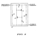
- a circuit for sinking and sourcing current through an output to the stator windings of an electric motor comprising, first and second power transistors each having a gate terminal, a source terminal and a drain terminal, the drain terminal of the first power transistor being coupled to a first source of operating potential, the source terminal of the second power transistor being coupled to a second source of operating potential, the source terminal of the first power transistor and the drain terminal of the second power transistor being coupled together to the output; a first circuit having a plurality of outputs for providing a plurality of control signals having a predetermined phase relationship therebetween; a second circuit for passing a plurality of output signals in response to the plurality of control signals while providing unilateral isolation for the first circuit from the potential developed across the first and second sources of operating potential; and first and second drive circuits each having an input and first and second outputs, the inputs being coupled for receiving first and second ones of the plurality of output signals of the second circuit, the first outputs being respectively coupled to the gate terminals of the first
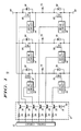
- control circuit 12 develops output voltage pulses each having a predetermined phase relationship, such as disclosed in the literature for Motorola part number MC33034.
- the output terminals of control circuit 12 are commonly known as phase-A, phase-B and phase-C; bottom-side and top-side output terminals.
- the phase-A bottom-side and phase-A top-side output terminals may for example be coupled to resistors 14 and 20, while the phase-B bottom-side and phase-B top-side output terminals are coupled to resistors 16 and 22, respectively.
Landscapes
- Engineering & Computer Science (AREA)
- Power Engineering (AREA)
- Control Of Motors That Do Not Use Commutators (AREA)
- Control Of Ac Motors In General (AREA)
- Control Of Direct Current Motors (AREA)
Applications Claiming Priority (2)
| Application Number | Priority Date | Filing Date | Title |
|---|---|---|---|
| US484946 | 1990-02-26 | ||
| US07/484,946 US4967336A (en) | 1990-02-26 | 1990-02-26 | High voltage bridge interface |
Publications (3)
| Publication Number | Publication Date |
|---|---|
| EP0444404A2 true EP0444404A2 (de) | 1991-09-04 |
| EP0444404A3 EP0444404A3 (en) | 1991-10-23 |
| EP0444404B1 EP0444404B1 (de) | 1997-10-08 |
Family
ID=23926293
Family Applications (1)
| Application Number | Title | Priority Date | Filing Date |
|---|---|---|---|
| EP91100366A Expired - Lifetime EP0444404B1 (de) | 1990-02-26 | 1991-01-14 | Hochspannungsbrückenschnittstelle für Wechselstrom- und bürstenlose Gleichstrommotor-Steuerung |
Country Status (5)
| Country | Link |
|---|---|
| US (1) | US4967336A (de) |
| EP (1) | EP0444404B1 (de) |
| JP (1) | JPH04229097A (de) |
| KR (1) | KR920000168A (de) |
| DE (1) | DE69127838T2 (de) |
Cited By (1)
| Publication number | Priority date | Publication date | Assignee | Title |
|---|---|---|---|---|
| WO2003047082A1 (de) * | 2001-11-20 | 2003-06-05 | Robert Bosch Gmbh | Schaltungsanordnung zum betreiben einer elektrischen maschine |
Families Citing this family (8)
| Publication number | Priority date | Publication date | Assignee | Title |
|---|---|---|---|---|
| DE4007566C2 (de) * | 1990-03-09 | 1998-07-16 | Siemens Ag | Leistungsverstärker für die Speisung einer Induktivität mit geschalteten Transistoren |
| US5103148A (en) * | 1990-11-06 | 1992-04-07 | Motorola, Inc. | Low voltage circuit to control high voltage transistor |
| US5517402A (en) * | 1992-06-04 | 1996-05-14 | Sanden Corporation | Inverter circuit with an improved inverter driving circuit |
| IT1266377B1 (it) * | 1993-05-31 | 1996-12-27 | Merloni Antonio Spa | Metodo di alimentazione di motori elettrici a induzione mediante inverter elettronici |
| JP3411437B2 (ja) * | 1996-02-23 | 2003-06-03 | 富士電機株式会社 | 電力用半導体モジュール |
| EP1258980B1 (de) * | 2001-05-17 | 2005-12-07 | STMicroelectronics S.r.l. | Treiberschaltung und Verfahren zur Verhinderung von Überspannungen auf Versorgungsleitungen während des Betriebes eines Gleichstrommotors |
| CA3025336A1 (en) * | 2010-09-30 | 2012-03-30 | Philips Lighting Holding B.V. | Apparatus and methods for supplying power |
| KR102167778B1 (ko) * | 2013-12-04 | 2020-10-20 | 엘지이노텍 주식회사 | 손떨림 보정 액추에이터 고전류 제어 시스템 |
Family Cites Families (8)
| Publication number | Priority date | Publication date | Assignee | Title |
|---|---|---|---|---|
| JPH0634587B2 (ja) * | 1982-05-06 | 1994-05-02 | 株式会社東芝 | 電圧形インバータ装置 |
| US4481434A (en) * | 1982-06-21 | 1984-11-06 | Eaton Corporation | Self regenerative fast gate turn-off FET |
| JPS59123478A (ja) * | 1982-12-28 | 1984-07-17 | Toshiba Corp | 電圧形インバ−タの制御装置 |
| JPH0634594B2 (ja) * | 1983-10-07 | 1994-05-02 | 株式会社東芝 | 電圧形インバ−タ |
| JPS6373898A (ja) * | 1986-09-12 | 1988-04-04 | Matsushita Electric Ind Co Ltd | インバ−タ装置 |
| KR900008393B1 (ko) * | 1986-10-02 | 1990-11-17 | 미츠비시 덴키 가부시키가이샤 | 인버터장치의 과전류보호회로 |
| JP2578159B2 (ja) * | 1988-04-18 | 1997-02-05 | 日本オーチス・エレベータ株式会社 | Pwmインバータ |
| US4875148A (en) * | 1988-12-16 | 1989-10-17 | Sundstrand Corporation | Control for producing a low magnitude voltage at the output of a PWM inverter |
-
1990
- 1990-02-26 US US07/484,946 patent/US4967336A/en not_active Expired - Lifetime
-
1991
- 1991-01-14 EP EP91100366A patent/EP0444404B1/de not_active Expired - Lifetime
- 1991-01-14 DE DE69127838T patent/DE69127838T2/de not_active Expired - Fee Related
- 1991-02-20 KR KR1019910002698A patent/KR920000168A/ko not_active Withdrawn
- 1991-02-26 JP JP3114207A patent/JPH04229097A/ja active Pending
Cited By (2)
| Publication number | Priority date | Publication date | Assignee | Title |
|---|---|---|---|---|
| WO2003047082A1 (de) * | 2001-11-20 | 2003-06-05 | Robert Bosch Gmbh | Schaltungsanordnung zum betreiben einer elektrischen maschine |
| US7027315B2 (en) | 2001-11-20 | 2006-04-11 | Robert Bosh Gmbh | Circuit arrangement for operating an electrical machine |
Also Published As
| Publication number | Publication date |
|---|---|
| JPH04229097A (ja) | 1992-08-18 |
| EP0444404A3 (en) | 1991-10-23 |
| US4967336A (en) | 1990-10-30 |
| DE69127838D1 (de) | 1997-11-13 |
| EP0444404B1 (de) | 1997-10-08 |
| DE69127838T2 (de) | 1998-03-26 |
| KR920000168A (ko) | 1992-01-10 |
Similar Documents
| Publication | Publication Date | Title |
|---|---|---|
| EP0365618B1 (de) | Elektronische steuerschaltungen, elektronisch geschaltete motorsysteme und verfahren | |
| US3916272A (en) | Speed control for an electronic commutated d-c motor | |
| US3942083A (en) | Brushless motor | |
| US4472666A (en) | Brushless DC motor | |
| US4740734A (en) | Control apparatus for brushless dc motors | |
| US4967336A (en) | High voltage bridge interface | |
| GB1560413A (en) | Dynamoelectric machines | |
| US5668450A (en) | Half-wave, brushless, four-phase DC motor with bifilar windings | |
| JPS6131424B2 (de) | ||
| US5764007A (en) | Micro-processor based motor control integrated circuit including a boost regulated DC-to-DC converter | |
| US5514939A (en) | Circuitry for switching the body nodes of driver transistors in drive circuitry for brushless DC motors | |
| EP0896422B1 (de) | Stromsteuerung für einen bürstenlosen Gleichstrommotor mit unabhängigen Wicklungen | |
| US3688172A (en) | Commutating device for brushless motor including magnetic diodes | |
| CA2009581A1 (en) | Current controlled full wave transistor bridge inverter for a multiple phase ac machine | |
| JPS644439B2 (de) | ||
| US4242624A (en) | Direct current stepper motor with a permanent magnet rotor and electronic commutation device | |
| US5541487A (en) | Driving circuit for stepping motor | |
| US5572096A (en) | Method and circuit for clamping the recirculation current in stator windings | |
| US7042182B2 (en) | Electronically commutated motor operable directly from AC power network | |
| Jahns | Designing intelligent muscle into industrial motion control | |
| US4458191A (en) | Step motor drive circuit | |
| EP4175161A1 (de) | Adaptive gleichrichtung zur verhinderung von strominversion in einem motorantrieb | |
| US5886487A (en) | DC motor driver having output FETS that conduct to rectify output overvoltage and undervoltage transients | |
| EP0177931B1 (de) | Motorantriebsschaltkreis | |
| US7800322B2 (en) | Isolation circuit for DC power sources |
Legal Events
| Date | Code | Title | Description |
|---|---|---|---|
| PUAI | Public reference made under article 153(3) epc to a published international application that has entered the european phase |
Free format text: ORIGINAL CODE: 0009012 |
|
| PUAL | Search report despatched |
Free format text: ORIGINAL CODE: 0009013 |
|
| AK | Designated contracting states |
Kind code of ref document: A2 Designated state(s): DE FR GB IT |
|
| AK | Designated contracting states |
Kind code of ref document: A3 Designated state(s): DE FR GB IT |
|
| 17P | Request for examination filed |
Effective date: 19920201 |
|
| 17Q | First examination report despatched |
Effective date: 19931202 |
|
| GRAG | Despatch of communication of intention to grant |
Free format text: ORIGINAL CODE: EPIDOS AGRA |
|
| GRAH | Despatch of communication of intention to grant a patent |
Free format text: ORIGINAL CODE: EPIDOS IGRA |
|
| GRAH | Despatch of communication of intention to grant a patent |
Free format text: ORIGINAL CODE: EPIDOS IGRA |
|
| GRAA | (expected) grant |
Free format text: ORIGINAL CODE: 0009210 |
|
| AK | Designated contracting states |
Kind code of ref document: B1 Designated state(s): DE FR GB IT |
|
| REF | Corresponds to: |
Ref document number: 69127838 Country of ref document: DE Date of ref document: 19971113 |
|
| ITF | It: translation for a ep patent filed | ||
| PGFP | Annual fee paid to national office [announced via postgrant information from national office to epo] |
Ref country code: GB Payment date: 19971229 Year of fee payment: 8 |
|
| PGFP | Annual fee paid to national office [announced via postgrant information from national office to epo] |
Ref country code: FR Payment date: 19980116 Year of fee payment: 8 |
|
| PGFP | Annual fee paid to national office [announced via postgrant information from national office to epo] |
Ref country code: DE Payment date: 19980120 Year of fee payment: 8 |
|
| ET | Fr: translation filed | ||
| PLBE | No opposition filed within time limit |
Free format text: ORIGINAL CODE: 0009261 |
|
| STAA | Information on the status of an ep patent application or granted ep patent |
Free format text: STATUS: NO OPPOSITION FILED WITHIN TIME LIMIT |
|
| 26N | No opposition filed | ||
| PG25 | Lapsed in a contracting state [announced via postgrant information from national office to epo] |
Ref country code: GB Free format text: LAPSE BECAUSE OF NON-PAYMENT OF DUE FEES Effective date: 19990114 |
|
| GBPC | Gb: european patent ceased through non-payment of renewal fee |
Effective date: 19990114 |
|
| PG25 | Lapsed in a contracting state [announced via postgrant information from national office to epo] |
Ref country code: FR Free format text: LAPSE BECAUSE OF NON-PAYMENT OF DUE FEES Effective date: 19990930 |
|
| PG25 | Lapsed in a contracting state [announced via postgrant information from national office to epo] |
Ref country code: DE Free format text: LAPSE BECAUSE OF NON-PAYMENT OF DUE FEES Effective date: 19991103 |
|
| REG | Reference to a national code |
Ref country code: FR Ref legal event code: ST |
|
| PG25 | Lapsed in a contracting state [announced via postgrant information from national office to epo] |
Ref country code: IT Free format text: LAPSE BECAUSE OF NON-PAYMENT OF DUE FEES Effective date: 20050114 |