EP0443877A1 - Aube de turbine à gaz - Google Patents
Aube de turbine à gaz Download PDFInfo
- Publication number
- EP0443877A1 EP0443877A1 EP91301456A EP91301456A EP0443877A1 EP 0443877 A1 EP0443877 A1 EP 0443877A1 EP 91301456 A EP91301456 A EP 91301456A EP 91301456 A EP91301456 A EP 91301456A EP 0443877 A1 EP0443877 A1 EP 0443877A1
- Authority
- EP
- European Patent Office
- Prior art keywords
- blade
- infill
- abrasive particles
- particles
- vibration
- Prior art date
- Legal status (The legal status is an assumption and is not a legal conclusion. Google has not performed a legal analysis and makes no representation as to the accuracy of the status listed.)
- Granted
Links
Images


Classifications
-
- F—MECHANICAL ENGINEERING; LIGHTING; HEATING; WEAPONS; BLASTING
- F01—MACHINES OR ENGINES IN GENERAL; ENGINE PLANTS IN GENERAL; STEAM ENGINES
- F01D—NON-POSITIVE DISPLACEMENT MACHINES OR ENGINES, e.g. STEAM TURBINES
- F01D11/00—Preventing or minimising internal leakage of working-fluid, e.g. between stages
- F01D11/08—Preventing or minimising internal leakage of working-fluid, e.g. between stages for sealing space between rotor blade tips and stator
- F01D11/12—Preventing or minimising internal leakage of working-fluid, e.g. between stages for sealing space between rotor blade tips and stator using a rubstrip, e.g. erodible. deformable or resiliently-biased part
-
- B—PERFORMING OPERATIONS; TRANSPORTING
- B24—GRINDING; POLISHING
- B24D—TOOLS FOR GRINDING, BUFFING OR SHARPENING
- B24D99/00—Subject matter not provided for in other groups of this subclass
-
- C—CHEMISTRY; METALLURGY
- C23—COATING METALLIC MATERIAL; COATING MATERIAL WITH METALLIC MATERIAL; CHEMICAL SURFACE TREATMENT; DIFFUSION TREATMENT OF METALLIC MATERIAL; COATING BY VACUUM EVAPORATION, BY SPUTTERING, BY ION IMPLANTATION OR BY CHEMICAL VAPOUR DEPOSITION, IN GENERAL; INHIBITING CORROSION OF METALLIC MATERIAL OR INCRUSTATION IN GENERAL
- C23C—COATING METALLIC MATERIAL; COATING MATERIAL WITH METALLIC MATERIAL; SURFACE TREATMENT OF METALLIC MATERIAL BY DIFFUSION INTO THE SURFACE, BY CHEMICAL CONVERSION OR SUBSTITUTION; COATING BY VACUUM EVAPORATION, BY SPUTTERING, BY ION IMPLANTATION OR BY CHEMICAL VAPOUR DEPOSITION, IN GENERAL
- C23C10/00—Solid state diffusion of only metal elements or silicon into metallic material surfaces
- C23C10/02—Pretreatment of the material to be coated
Definitions
- This invention relates to gas turbine blades and in particular relates to the production of blade tip seals.
- the matrix comprises a major part of cobalt and minor parts of chromium, tantalum and alumina while the lining material of the shroud comprises a major part of cobalt with minor parts of nickel, chromium and aluminium and a small quantity of yttrium.
- the method by which such tips are produced is extremely expensive.
- detonation spray coating of the matrix is used.
- the abrasive portion of the tip is then formed on the inner tip portion by electrodeposition of alternating layers of chromium and nickel about the abrasive particles.
- the outer tip portion can then be aluminided to produce a matrix alloy of NiCrAl.
- a method of producing a gas turbine blade having an abrasive tip comprises producing a binding coat on the tip of the blade body by electrodeposition, the binding coat comprising MCrAlY where M is one or more of iron, nickel and cobalt, anchoring to the binding coat coarse particles of an abrasive material by composite electrodeposition from a bath of plating solution having the abrasive particles suspended therein, and then plating an infill around the abrasive particles.
- a tip which comprises a) a binding layer of MCrAlY which gives extremely good protection against oxidation and corrosion and provides a base on which the particle containing layer can be anchored, b) a layer of an anchoring material, preferably cobalt or MCrAlY with a preferred thickness of less than 30 ⁇ m, perhaps 20 ⁇ m or less and even as low as 2-10 ⁇ m, which holds the abrasive particles (which will have an average particle diameter substantially greater than the thickness of the anchoring layer) to the binding layer, and c) a further layer, preferably of MCrAlY, which infills around the particles and holds them firmly while allowing them to protrude, if necessary, to enable them to maximise their abrasive function.
- Deposition of the complete tip will, in most cases, be followed by a heat treatment step to homogenise the layers to produce what, in effect, will approach a single homogenous layer (of MCrAlY if the three layers are all MCrAlY) with particles in, and possibly protruding from, the uppermost portion thereof.
- Various particles may be employed. Examples include zirconia, alumina and various nitrides, silicides and borides known from the abrasive art.
- the preferred abrasive is cubic boron nitride, preferably having a particle size between 125 and 150 ⁇ m. It is possible for the infill, or at least the upper or outer portion thereof, to include abrasive particles of a size substantially smaller than the main abrasive particles, for example approximately 20 ⁇ m.
- the MCrAlY of the binding coat, the anchoring layer where this is MCrAlY, and the infill where this is MCrAlY may have various compositions of which suitable examples are described in British Patent Specification GB-2167446B.
- the electrodeposition may be effected by various forms of apparatus. However, suitable forms of apparatus are described in British Patent Specification Nos. GB-2182055A and European Patent Specification No. EP-0355051A. These describe apparatus which comprises an electroplating tank which is divided into two zones by a vertical wall extending from close to the bottom of the tank up to just beneath the surface of the solution in the bath.
- the deposition of the infill is preferably accompanied by vibration of the blade, preferably in a direction axial of the blade or containing a substantial component in this direction. It is believed that such vibration ensures an even distribution of CrAlY particles, particularly in those regions which are shaded by the overhang of the abrasive particles and which regions might otherwise be depleted of particles.
- the frequency of the vibration is preferably between 10 Hz and 1 kHz, the particularly preferred figure being about 50 Hz. A peak acceleration of up to 10 g is preferred.
- each lower level phase is longer than each higher level phase; thus the lower level phases may be for between 30 seconds and 2 minutes duration with a peak acceleration of about 2 g and the higher level phases may be for about 5 seconds duration with a peak acceleration of about 10 g.
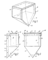
- the apparatus shown in Figure 1 to 3 of the drawings comprises a vessel or container 1 having a parallelepiped shaped upper portion 2 and a downwardly tapering lower portion 3 in the form of an inverted pyramid which is skewed so that one side face 4 forms a continuation of one side face 5 of the upper portion.
- the vessel 1 contains a partition 6 which lies in a vertical plane parallel to the side faces 4 and 5 of the vessel and makes contact at its side edges 7 and 8 with the adjacent vertical and sloping faces of the vessel.
- the partition thus divides the vessel into a larger working zone 9 and a smaller return zone 11.
- the partition 6 terminates at a horizontal edge 12 above the bottom of the vessel to afford an interconnection 13 between the working zone 9 and the return zone 11.
- the partition 6 terminates at a horizontal edge 14 below the top edges of the vessel 1.
- an air inlet 15 which is connected to an air pump (not shown).
- a fixture 21 to which the workpieces to be coated are mounted, the fixture 21 being arranged to move the workpieces within the vessel in a manner to be described in greater detail below.
- Conductors are provided to apply a voltage to the workpiece mounted on the fixture 21 relative to an anode which is suspended in the working zone.
- the workpieces are mounted on the fixture 21 which is positioned in the vessel as shown.
- the vessel is filled to a level 17 above the top edge 14 of the partition 6 with a plating solution containing particles to be co-deposited. Air is admitted to the inlet 15 and this rises up the return zone 11, raising solution and entrained particles. At the top of the return zone, the air escapes and the solution and particles flow over the broad crested weir formed by the top edge 14 of the partition and flow down past the workpieces on the fixture 21. At the bottom of the working zone 9, the particles tend to settle and slide down the inclined sides of the vessel towards the interconnection 13 where they are again entrained in the solution and carried round again.
- the fixture 21 on which the workpieces to be coated are mounted is shown in detail in Figure 4, in simplified form in Figures 2 and 3 and is omitted from Figure 1 for reasons of clarity.
- the fixture 21 comprises a deck 22 which fits over the top of the vessel 1, a depending pillar 23 towards one end and a pair of depending guides 24 at the other end.
- the guides 24 have facing guideways in which slides a cross-head 25 carrying a vertical rack 26 which passes upwards through a hole 27 in the deck 22 and meshes with a pinion 28 driven by a reversible electric motor 29.
- the deck 22 supports a second electric motor 31 which drives a vertical shaft 32 carrying a bevel pinion 33 which engages a crown-wheel 34 fixed to one end of a spindle 35 mounted in the pillar 23.
- the other end of the spindle 35 is connected by a universal joint 36 to a trunnion 51 on one end of a jig 52 which is only shown diagrammatically in Figure 4 but is shown in greater detail in Figures 5 and 6.
- a second trunnion 53 which enters a spherical bearing 38 in the cross head 25.
- a vibrator 42 mounted on the deck 22 and is connected by lines 45 to the motors 29 and 31.
- the controller 43 is designed so that, when required, the motor 31 is driven in one direction only (but with the possibility of a stop-start or two level action) so as to rotate the spindle 35 about a nominally horizontal axis (the x-axis).
- the controller 43 is designed to drive, when required, the motor 29 alternately in opposite directions to reciprocate the cross-head 24 and so superimpose on the rotation about the x-axis an oscillatory rotation about a rotating axis in the universal joint 36 (the y-axis).
- the jig 52 comprises a generally box-like unit having open sides and comprising a first end 54 connected to the trunnion 51, a second end 55 connected to the trunnion 53, a base 56 rigidly connected and joining the ends 54 and 55 and a removable lid 57.
- Each of the ends 54,55 carries fixed studs 58 which butt against the underside of the lid 57 and bolts 59 which pass freely through apertures in the lid 57 and engage in threaded bores in the upper edges of the ends 54 and 55 to enable the lid 57 to be screwed down onto the stud 58.
- the base 56 is formed with grooves 61 to receive the roots of turbine blades to be tipped and the lid 57 is formed with aerofoil shaped apertures 62 to receive the outer ends of the blades.
- the blades are retained in position in the groove 61 by screws 63.
- a plate 64 at the rear end of the grooves 61 limits their movement out of the groove 61.
- the blade is degreased in vapour degreaser or a proprietary degreasing agent such as Genklene.
- the root of the blade With the top plate of the jig 52 removed, the root of the blade is then introduced into one of the grooves 61 in the bottom plate 56 until it engages the back plate 64 and it is then clamped in position by tightening of the screw 63 against the underside of the root.
- the top plate is then replaced and held down by tightening of the screws 59. In this condition the tip of the blade is approximately level with the top surface of the plate 57 with a gap of approximately 1 mm extending all the way around the periphery of the blade between it and the adjacent edge of the aperture 62.
- the blade and the holder are then grit blasted as necessary to provide a key for the masking wax and the holder is then inserted into a wax bath to mask all the surfaces of the holder and blade.
- the upper surface of the plate 57 and the tip of the blade are then grit blasted with 50-100 micrometres alumina.
- the jig with the blade therein is then given an anodic clean for five minutes at 6 to 8 volts in a cleaning solution consisting of sodium hydroxide/gluconate/thiocyanate and is then rinsed thoroughly in cold running water.
- the exposed surfaces of the blade and the plate 57 are then etched in a solution comprising approximately 300 gms/l ferric chloride, 58 gms/l hydrochloric acid and 1% hydrofluoric acid (60% w/w) for five minutes at room temperature and again rinsed thoroughly in cold running water.
- the jig is then placed in a nickel chloride bath to provide a strike which is given at 3.87 amps per square decimetre (36 amps per square foot) for four minutes.
- the strike bath comprises approximately 350 gms/l nickel chloride and 33 gms/l hydrochloric acid.
- the jig 52 is then placed in the fixture shown in Figure 4 and the fixture is placed in the apparatus shown in Figures 1 to 3.
- the jig and fixture may be assembled before the pre-treatment procedures.
- the bath contains a cobalt plating solution with 2 to 5 weight percent particles of CrAlY containing 67-68 parts by weight Cr, 29-31 parts by weight Al and 1.5-2.4 parts by weight Y with a size distribution in the bath as given in the following table, the columns relating to the size band being the upper and lower limits of the cut measured in micrometres.
- the size distribution in the as-deposited coating will be similar but somewhat smaller due to selection in the plating process.
- Plating is continued for a period of 4 hours at a current density of 1.075 amps per decimetre (10 amps per square foot) with the controller 43 set to rotate the motor 31 at such a speed as to rotate the holder 52 at 0.33 revolutions per minute.
- the motor 29 is stationary during this operation but air is admitted continuously to maintain circulation of the solution and suspended CrAlY particles.
- This plating provides a coat of CoCrAlY on the tip of the blade to a thickness of between 25 and 50 ⁇ m.
- the production of the binding coat may be performed using the fixture shown in Figure 8 and employing vibration as will be described in greater detail below. Deposition of CoCrAlY from the bath described will produce a layer having a composition which is approximately in weight percent: Al 10, Cr 23, Y 0.5 and the balance Co.
- the holder is then rinsed over the tank with demineralised water and then removed from the region of the tank and rinsed in running water.
- the holder is then placed in a Woods nickel bath or 1 volume percent sulphuric acid bath to reactivate the surface and the fixture is then placed in a second bath similar to the first bath except that in place of the CrAlY particles it contains particles of cubic boron nitride of 100/200 mesh i.e. approximately 125-150 ⁇ m.
- plating is commenced at 2.7 amps per decimetre (25 amps per square foot) and air is switched on for a period of 5 seconds.
- the boron nitride particles go into circulation and cascade over the blade and holder.
- Plating is then continued without the admission of air for a period of approximately 40 minutes to secure the particles resting on the blade tip to the tip. It may be found that in some cases it is beneficial to have a further burst of 5 seconds of air after 20 minutes to ensure a uniform and maximum distribution of CBN particles over the blade tip surface.
- the motor 31 is now activated to turn the holder 52 slowly through 180° to allow excess and unanchored particles of CBN to fall off.
- the fixture 21 is now removed from the CBN bath, is rinsed over the tank and is then rinsed in a static bath and finally rinsed thoroughly in running water.
- the surfaces being coated are then reactivated in a Woods nickel or 1% sulphuric acid bath and the fixture is replaced in the CoCrAlY bath.
- the motor 31 is activated to rotate the jig at 0.33 rpm and plating is continued for 7 hours at 1.075 amps per decimetre (10 amps per square foot) for 7 hours (with continuous admission of air to maintain circulation of the solution and suspended CrAlY particles) to fill the spaces under and around the CBN particles with CoCrAlY to a depth which, as can be seen in Figure 7, leaves the tips of the abrasive particles slightly proud of the surrounding CoCrAlY.
- the holder may be rotated with the start/stop action described in European patent application number 89307713.1.
- the motor 31 is controlled to produce a rotation of the jig 52 unidirectionally and at a speed of one rotation in 3 minutes with the rotation being intermittent with 10 second stop periods being interspersed with three second go periods.
- the vibrator 42 may be used with the motor 31 inactive, the jig 52 being held in the position shown in Figure 4 with the tip surfaces of the blades horizontal and upwards.
- the vibrator 42 is arranged to give a vibration at a frequency of 50 Hz with alternating periods of high intensity and low intensity vibration, the high intensity periods having a duration of 5 seconds and a peak acceleration of 10 g and the low intensity periods having a duration of 75 seconds with a peak acceleration of 2 g.
- a combination of rotation and vibration may be used, either simultaneous or alternating. Where rotation is employed it is probable that any vibration that may be considered desirable need be only at the low intensity level referred to above.
- the vibration and the rotation produce homogeneous infill and ensure that the CrAlY particles reach the areas shadowed by the CBN particles.
- the fixture is removed and the holder is rinsed over the tank with demineralised water and then rinsed thoroughly in running water.
- the masking material is then removed and the blade is taken out of the jig and degreased.
- the blade is then heat treated for between 1/2 and 1 hour at 1090 plus or minus 10°C in vacuum or in 50-100 millibar partial pressure argon and fast gas quenched.
- the blade is then aluminized by one of the well-known processes such as pack aluminizing.
- the tip produced in the manner described is shown in section in Figure 7 and can be seen to comprise the body 80 of the blade, a binding coat 81 of MCrAlY of a thickness, in this example, of 25-50 ⁇ m, an anchoring coat 82 of MCrAlY of a thickness of 10-20 ⁇ m in which is anchored the bottom portions of the abrasive particles 83 of cubic boron nitride with a particle size of 125-150 ⁇ m, and an infill 84 of MCrAlY with a thickness of 70-110 ⁇ m.
- a simplified form of fixture 91 suitable for producing either or both the binding layer and the infill is shown in Figure 8 and this may be used in place of the fixture shown in Figure 4.
- the fixture 91 comprises a jig 92 having a base 93 similar to the base 56 of the jig 52 and having grooves 94 to receive the roots of the blades 95, the blades being locked in position by means not shown, such as screws similar to the screws 63 of the jig 52.
- the base 93 is carried by a bail 96 at the bottom of a rod 97 depending from a vibrator 98 carried on a beam 99 from which the fixture can be suspended in the working zone 9 of the vessel 1 shown in Figures 1 to 3.
- the two level vibration described in relation to Figure 4 is used, i.e. longer periods of duration 75 seconds at a lower intensity with a peak acceleration of 2 g alternating with shorter periods of 5 seconds with a peak acceleration of 10 g.
- particles of pure cubic boron nitride it would be possible to use particles of this or another abrasive which are coated with a material which will protect them, for a time at least, from severe oxidation.
- particles of this or another abrasive which are coated with a material which will protect them, for a time at least, from severe oxidation.
- cubic boron nitride particles which had been given a substantially air-impermeable coating of aluminium oxide or an intermetallic such as nickel aluminide.
Applications Claiming Priority (2)
| Application Number | Priority Date | Filing Date | Title |
|---|---|---|---|
| GB9004132 | 1990-02-23 | ||
| GB9004132A GB2241506A (en) | 1990-02-23 | 1990-02-23 | Method of producing a gas turbine blade having an abrasive tip by electrodepo- sition. |
Publications (2)
| Publication Number | Publication Date |
|---|---|
| EP0443877A1 true EP0443877A1 (fr) | 1991-08-28 |
| EP0443877B1 EP0443877B1 (fr) | 1993-12-29 |
Family
ID=10671519
Family Applications (1)
| Application Number | Title | Priority Date | Filing Date |
|---|---|---|---|
| EP91301456A Expired - Lifetime EP0443877B1 (fr) | 1990-02-23 | 1991-02-22 | Aube de turbine à gaz |
Country Status (7)
| Country | Link |
|---|---|
| US (1) | US5076897A (fr) |
| EP (1) | EP0443877B1 (fr) |
| JP (1) | JP3304104B2 (fr) |
| CA (1) | CA2036904C (fr) |
| DE (1) | DE69100853T2 (fr) |
| ES (1) | ES2047373T3 (fr) |
| GB (1) | GB2241506A (fr) |
Cited By (15)
| Publication number | Priority date | Publication date | Assignee | Title |
|---|---|---|---|---|
| EP0484115A1 (fr) * | 1990-11-01 | 1992-05-06 | General Electric Company | Extrémité abrasive pour aube de turbine |
| EP0601490A1 (fr) * | 1992-12-09 | 1994-06-15 | Mtu Motoren- Und Turbinen-Union MàNchen Gmbh | Procédé pour la préparation de pièces à travailler ou de substrats avec des revêtements composites |
| DE4442455A1 (de) * | 1994-11-29 | 1996-05-30 | Bmw Rolls Royce Gmbh | Verfahren zum Aufbringen einer Deckplatte auf eine Turbinenschaufel |
| WO2002103165A1 (fr) * | 2001-06-13 | 2002-12-27 | Mitsubishi Heavy Industries, Ltd. | Procede de formation d'une couche resistant a l'abrasion pour aubes en deplacement, couche resistant a l'abrasion et procede de regeneration de celle-ci, et turbine a gaz y relative |
| EP1422054A1 (fr) * | 2002-11-21 | 2004-05-26 | Siemens Aktiengesellschaft | Structure laminée pour de turbine à gaz |
| WO2004055245A2 (fr) * | 2002-12-18 | 2004-07-01 | Siemens Aktiengesellschaft | Procede pour deposer un alliage sur un substrat |
| EP1526192A1 (fr) * | 2003-10-24 | 2005-04-27 | Siemens Aktiengesellschaft | Procédé électrolytique pour la déposition d'une couche graduelle sur un substrat et composant |
| US6887036B2 (en) | 2001-11-09 | 2005-05-03 | Mitsubishi Heavy Industries, Ltd. | Turbine and manufacturing method therefor |
| EP1964945A2 (fr) * | 2007-02-27 | 2008-09-03 | Turbine Overhaul Services Private Limited | Système et procédé pour dépôt électrique de composants métalliques |
| US7473072B2 (en) | 2005-02-01 | 2009-01-06 | Honeywell International Inc. | Turbine blade tip and shroud clearance control coating system |
| EP2019238A1 (fr) * | 2007-07-25 | 2009-01-28 | Siemens Aktiengesellschaft | Couche de frottement pour un joint d'étanchéité d'un arbre de rotation et procédé d'application |
| EP2241648A3 (fr) * | 2009-04-17 | 2011-11-30 | United Technologies Corporation | Revêtement thermique abrasif |
| DE102010024224A1 (de) | 2010-06-18 | 2011-12-22 | Mtu Aero Engines Gmbh | Verfahren und Vorrichtung zum Aufbringen einer Dispersionsschicht mit einem Matrixwerkstoff und Feststoffteilchen |
| EP3056679A1 (fr) * | 2015-02-12 | 2016-08-17 | United Technologies Corporation | Pointe de lame abrasive présentant une usure améliorée à taux d'interaction élevé |
| CN109338288A (zh) * | 2018-09-17 | 2019-02-15 | 中国科学院金属研究所 | 一种燃气轮机叶片叶尖防护涂层及其制备方法和应用 |
Families Citing this family (45)
| Publication number | Priority date | Publication date | Assignee | Title |
|---|---|---|---|---|
| GB2254338B (en) * | 1988-07-29 | 1993-02-03 | Baj Ltd | Improvements relating to the production of coatings |
| DE4121839C2 (de) * | 1991-07-02 | 2003-01-09 | Werner Hermann Wera Werke | Werkzeug mit drehmomentübertragenden Arbeitsflächen und Verfahren zur Herstellung desselben |
| US5389228A (en) * | 1993-02-04 | 1995-02-14 | United Technologies Corporation | Brush plating compressor blade tips |
| GB9303853D0 (en) * | 1993-02-25 | 1993-04-21 | Baj Coatings Ltd | Rotor blades |
| US5437724A (en) * | 1993-10-15 | 1995-08-01 | United Technologies Corporation | Mask and grit container |
| US5486281A (en) * | 1993-10-15 | 1996-01-23 | United Technologies Corporation | Method for CBN tipping of HPC integrally bladed rotors |
| US5603603A (en) * | 1993-12-08 | 1997-02-18 | United Technologies Corporation | Abrasive blade tip |
| GB9326082D0 (en) * | 1993-12-21 | 1994-02-23 | Baj Coatings Ltd | Rotor blades |
| US5952110A (en) * | 1996-12-24 | 1999-09-14 | General Electric Company | Abrasive ceramic matrix turbine blade tip and method for forming |
| US5902471A (en) * | 1997-10-01 | 1999-05-11 | United Technologies Corporation | Process for selectively electroplating an airfoil |
| US5935407A (en) * | 1997-11-06 | 1999-08-10 | Chromalloy Gas Turbine Corporation | Method for producing abrasive tips for gas turbine blades |
| US6610419B1 (en) * | 1998-04-29 | 2003-08-26 | Siemens Akteingesellschaft | Product with an anticorrosion protective layer and a method for producing an anticorrosion protective |
| US20040180233A1 (en) * | 1998-04-29 | 2004-09-16 | Siemens Aktiengesellschaft | Product having a layer which protects against corrosion. and process for producing a layer which protects against corrosion |
| US5997248A (en) * | 1998-12-03 | 1999-12-07 | Sulzer Metco (Us) Inc. | Silicon carbide composition for turbine blade tips |
| GB2362654A (en) * | 2000-05-26 | 2001-11-28 | Keteca Usa Inc | Diamond saw blade |
| SE519466C2 (sv) * | 2000-12-07 | 2003-03-04 | Swedev Ab | Schaber - eller rakelblad med beläggning av nickel innefattandes nötningsbeständiga partiklar och metod vid dess framställning |
| JP3801452B2 (ja) | 2001-02-28 | 2006-07-26 | 三菱重工業株式会社 | 耐摩耗性コーティング及びその施工方法 |
| JP2002256808A (ja) * | 2001-02-28 | 2002-09-11 | Mitsubishi Heavy Ind Ltd | 燃焼エンジン、ガスタービン及び研磨層 |
| US7131068B2 (en) | 2001-05-25 | 2006-10-31 | Learning Tree International | System and method for electronic presentations having simultaneous display windows in a control screen |
| EP1391537B1 (fr) | 2001-05-31 | 2012-02-22 | Mitsubishi Heavy Industries, Ltd. | Procede et materiau de formage de revetement, et feuille de formage de revetement abrasif |
| DE10128507B4 (de) * | 2001-06-14 | 2008-07-17 | Mtu Aero Engines Gmbh | Verwendung einer Vorrichtung zum chemischen oder elektrochemischen Bearbeiten von Bauteilen |
| US6780458B2 (en) * | 2001-08-01 | 2004-08-24 | Siemens Westinghouse Power Corporation | Wear and erosion resistant alloys applied by cold spray technique |
| US6706319B2 (en) | 2001-12-05 | 2004-03-16 | Siemens Westinghouse Power Corporation | Mixed powder deposition of components for wear, erosion and abrasion resistant applications |
| US7316850B2 (en) * | 2004-03-02 | 2008-01-08 | Honeywell International Inc. | Modified MCrAlY coatings on turbine blade tips with improved durability |
| US7836593B2 (en) | 2005-03-17 | 2010-11-23 | Siemens Energy, Inc. | Cold spray method for producing gas turbine blade tip |
| US7140952B1 (en) * | 2005-09-22 | 2006-11-28 | Pratt & Whitney Canada Corp. | Oxidation protected blade and method of manufacturing |
| EP1989399B1 (fr) * | 2006-02-24 | 2012-02-08 | MT Coatings, LLC | Revêtement rugosifié pour composants de moteur de turbine à gaz |
| GB0621184D0 (en) | 2006-10-25 | 2006-12-06 | Rolls Royce Plc | Method for treating a component of a gas turbine engine |
| GB0701397D0 (en) | 2007-01-25 | 2007-03-07 | Rolls Royce Plc | Apparatus and method for calibrating a laser deposition system |
| GB2449862B (en) * | 2007-06-05 | 2009-09-16 | Rolls Royce Plc | Method for producing abrasive tips for gas turbine blades |
| DE102009007666A1 (de) | 2009-02-05 | 2010-08-12 | Mtu Aero Engines Gmbh | Verfahren zur Herstellung einer verschleißfesten Beschichtung auf einem Bauteil |
| DE102009055914A1 (de) * | 2009-11-27 | 2011-06-09 | Rolls-Royce Deutschland Ltd & Co Kg | Dichtringe für eine Labyrinthdichtung |
| US20130224504A1 (en) * | 2012-02-24 | 2013-08-29 | Henry H. Thayer | Method for coating a substrate |
| US9598973B2 (en) * | 2012-11-28 | 2017-03-21 | General Electric Company | Seal systems for use in turbomachines and methods of fabricating the same |
| DE102013218687A1 (de) * | 2013-09-18 | 2015-04-02 | MTU Aero Engines AG | Galvanisch hergestellte Verschleißschutzbeschichtung und Verfahren hierfür |
| US9909428B2 (en) | 2013-11-26 | 2018-03-06 | General Electric Company | Turbine buckets with high hot hardness shroud-cutting deposits |
| CN104099657A (zh) * | 2014-06-25 | 2014-10-15 | 北京理工大学 | 一种MCrAlY合金涂层的制备方法 |
| US9957629B2 (en) | 2014-08-27 | 2018-05-01 | Praxair S.T. Technology, Inc. | Electroplated coatings |
| US10794394B2 (en) * | 2015-04-15 | 2020-10-06 | Raytheon Technologies Corporation | Abrasive tip for composite fan blades |
| US10450876B2 (en) * | 2015-04-15 | 2019-10-22 | United Technologies Corporation | Abrasive tip blade manufacture methods |
| US11078588B2 (en) * | 2017-01-09 | 2021-08-03 | Raytheon Technologies Corporation | Pulse plated abrasive grit |
| US10822967B2 (en) * | 2017-02-01 | 2020-11-03 | Raytheon Technologies Corporation | Wear resistant coating, method of manufacture thereof and articles comprising the same |
| US11149744B2 (en) * | 2017-09-19 | 2021-10-19 | Raytheon Technologies Corporation | Turbine engine seal for high erosion environment |
| US11536151B2 (en) * | 2020-04-24 | 2022-12-27 | Raytheon Technologies Corporation | Process and material configuration for making hot corrosion resistant HPC abrasive blade tips |
| CN115637400B (zh) * | 2022-11-18 | 2023-03-21 | 矿冶科技集团有限公司 | 一种具有高结合力耐磨防护涂层的钛合金叶片及其制备方法 |
Citations (3)
| Publication number | Priority date | Publication date | Assignee | Title |
|---|---|---|---|---|
| US4155721A (en) * | 1974-11-06 | 1979-05-22 | Fletcher J Lawrence | Bonding process for grinding tools |
| US4232995A (en) * | 1978-11-27 | 1980-11-11 | General Electric Company | Gas seal for turbine blade tip |
| GB2167446A (en) * | 1984-10-05 | 1986-05-29 | Baj Ltd | Electrode deposited composite coating |
Family Cites Families (4)
| Publication number | Priority date | Publication date | Assignee | Title |
|---|---|---|---|---|
| US3830711A (en) * | 1972-01-19 | 1974-08-20 | Bristol Aerojet Ltd | Electrodeposition of composite coatings |
| US4169020A (en) * | 1977-12-21 | 1979-09-25 | General Electric Company | Method for making an improved gas seal |
| NL193727C (nl) * | 1984-10-05 | 2000-08-04 | Secr Defence | Bekleding op basis van metaal en werkwijze voor het vormen van een metaalbekleding op een substraat. |
| FR2615871B1 (fr) * | 1987-05-26 | 1989-06-30 | Snecma | Pieces de turbomachine en superalliage comportant un revetement protecteur metalloceramique |
-
1990
- 1990-02-23 GB GB9004132A patent/GB2241506A/en not_active Withdrawn
-
1991
- 1991-02-21 US US07/659,017 patent/US5076897A/en not_active Expired - Lifetime
- 1991-02-22 EP EP91301456A patent/EP0443877B1/fr not_active Expired - Lifetime
- 1991-02-22 DE DE91301456T patent/DE69100853T2/de not_active Expired - Lifetime
- 1991-02-22 ES ES91301456T patent/ES2047373T3/es not_active Expired - Lifetime
- 1991-02-22 JP JP02828291A patent/JP3304104B2/ja not_active Expired - Lifetime
- 1991-02-22 CA CA002036904A patent/CA2036904C/fr not_active Expired - Lifetime
Patent Citations (3)
| Publication number | Priority date | Publication date | Assignee | Title |
|---|---|---|---|---|
| US4155721A (en) * | 1974-11-06 | 1979-05-22 | Fletcher J Lawrence | Bonding process for grinding tools |
| US4232995A (en) * | 1978-11-27 | 1980-11-11 | General Electric Company | Gas seal for turbine blade tip |
| GB2167446A (en) * | 1984-10-05 | 1986-05-29 | Baj Ltd | Electrode deposited composite coating |
Cited By (23)
| Publication number | Priority date | Publication date | Assignee | Title |
|---|---|---|---|---|
| EP0484115A1 (fr) * | 1990-11-01 | 1992-05-06 | General Electric Company | Extrémité abrasive pour aube de turbine |
| EP0601490A1 (fr) * | 1992-12-09 | 1994-06-15 | Mtu Motoren- Und Turbinen-Union MàNchen Gmbh | Procédé pour la préparation de pièces à travailler ou de substrats avec des revêtements composites |
| DE4442455A1 (de) * | 1994-11-29 | 1996-05-30 | Bmw Rolls Royce Gmbh | Verfahren zum Aufbringen einer Deckplatte auf eine Turbinenschaufel |
| WO2002103165A1 (fr) * | 2001-06-13 | 2002-12-27 | Mitsubishi Heavy Industries, Ltd. | Procede de formation d'une couche resistant a l'abrasion pour aubes en deplacement, couche resistant a l'abrasion et procede de regeneration de celle-ci, et turbine a gaz y relative |
| US6887036B2 (en) | 2001-11-09 | 2005-05-03 | Mitsubishi Heavy Industries, Ltd. | Turbine and manufacturing method therefor |
| WO2004045844A1 (fr) * | 2002-11-21 | 2004-06-03 | Siemens Aktiengesellschaft | Systeme de couches |
| EP1422054A1 (fr) * | 2002-11-21 | 2004-05-26 | Siemens Aktiengesellschaft | Structure laminée pour de turbine à gaz |
| US7250222B2 (en) | 2002-11-21 | 2007-07-31 | Siemens Aktiengesellschaft | Layer system |
| DE10259362A1 (de) * | 2002-12-18 | 2004-07-08 | Siemens Ag | Verfahren zum Abscheiden einer Legierung auf ein Substrat |
| WO2004055245A3 (fr) * | 2002-12-18 | 2004-09-02 | Siemens Ag | Procede pour deposer un alliage sur un substrat |
| WO2004055245A2 (fr) * | 2002-12-18 | 2004-07-01 | Siemens Aktiengesellschaft | Procede pour deposer un alliage sur un substrat |
| EP1526192A1 (fr) * | 2003-10-24 | 2005-04-27 | Siemens Aktiengesellschaft | Procédé électrolytique pour la déposition d'une couche graduelle sur un substrat et composant |
| US7473072B2 (en) | 2005-02-01 | 2009-01-06 | Honeywell International Inc. | Turbine blade tip and shroud clearance control coating system |
| EP1964945A3 (fr) * | 2007-02-27 | 2011-05-11 | Turbine Overhaul Services Private Limited | Système et procédé pour dépôt électrique de composants métalliques |
| EP1964945A2 (fr) * | 2007-02-27 | 2008-09-03 | Turbine Overhaul Services Private Limited | Système et procédé pour dépôt électrique de composants métalliques |
| EP2019238A1 (fr) * | 2007-07-25 | 2009-01-28 | Siemens Aktiengesellschaft | Couche de frottement pour un joint d'étanchéité d'un arbre de rotation et procédé d'application |
| EP2241648A3 (fr) * | 2009-04-17 | 2011-11-30 | United Technologies Corporation | Revêtement thermique abrasif |
| US8186946B2 (en) | 2009-04-17 | 2012-05-29 | United Technologies Corporation | Abrasive thermal coating |
| DE102010024224A1 (de) | 2010-06-18 | 2011-12-22 | Mtu Aero Engines Gmbh | Verfahren und Vorrichtung zum Aufbringen einer Dispersionsschicht mit einem Matrixwerkstoff und Feststoffteilchen |
| DE102010024224B4 (de) * | 2010-06-18 | 2016-08-18 | MTU Aero Engines AG | Verfahren und Vorrichtung zum Aufbringen einer Dispersionsschicht mit einem Matrixwerkstoff und Feststoffteilchen |
| EP3056679A1 (fr) * | 2015-02-12 | 2016-08-17 | United Technologies Corporation | Pointe de lame abrasive présentant une usure améliorée à taux d'interaction élevé |
| CN109338288A (zh) * | 2018-09-17 | 2019-02-15 | 中国科学院金属研究所 | 一种燃气轮机叶片叶尖防护涂层及其制备方法和应用 |
| CN109338288B (zh) * | 2018-09-17 | 2020-09-18 | 中国科学院金属研究所 | 一种燃气轮机叶片叶尖防护涂层及其制备方法和应用 |
Also Published As
| Publication number | Publication date |
|---|---|
| DE69100853T2 (de) | 1994-04-21 |
| GB2241506A (en) | 1991-09-04 |
| JPH04218698A (ja) | 1992-08-10 |
| ES2047373T3 (es) | 1994-02-16 |
| CA2036904C (fr) | 2000-06-13 |
| JP3304104B2 (ja) | 2002-07-22 |
| DE69100853D1 (de) | 1994-02-10 |
| CA2036904A1 (fr) | 1991-08-24 |
| US5076897A (en) | 1991-12-31 |
| EP0443877B1 (fr) | 1993-12-29 |
| GB9004132D0 (en) | 1990-04-18 |
Similar Documents
| Publication | Publication Date | Title |
|---|---|---|
| EP0443877B1 (fr) | Aube de turbine à gaz | |
| US5702574A (en) | Jig for coating rotor blades | |
| EP0724658B1 (fr) | Revetement protecteur | |
| US5551840A (en) | Abrasive blade tip | |
| RU2142520C1 (ru) | Защитное покрытие | |
| CA2306781C (fr) | Procede de production d'extremites abrasives d'aubes de turbine a gaz | |
| EP0686229B1 (fr) | Procede de production d'une pointe abrasive sur une aube de turbine | |
| EP0355051B1 (fr) | Procédé de revêtement | |
| CA2120615C (fr) | Revetements composites electrodeposes | |
| GB2254338A (en) | Electrolytic or electroless codeposition of particles and metal |
Legal Events
| Date | Code | Title | Description |
|---|---|---|---|
| PUAI | Public reference made under article 153(3) epc to a published international application that has entered the european phase |
Free format text: ORIGINAL CODE: 0009012 |
|
| AK | Designated contracting states |
Kind code of ref document: A1 Designated state(s): BE DE ES FR GB IT NL SE |
|
| 17P | Request for examination filed |
Effective date: 19920221 |
|
| 17Q | First examination report despatched |
Effective date: 19930419 |
|
| RAP1 | Party data changed (applicant data changed or rights of an application transferred) |
Owner name: BAJ COATINGS LIMITED |
|
| GRAA | (expected) grant |
Free format text: ORIGINAL CODE: 0009210 |
|
| ITF | It: translation for a ep patent filed |
Owner name: BARZANO' E ZANARDO ROMA S.P.A. |
|
| AK | Designated contracting states |
Kind code of ref document: B1 Designated state(s): BE DE ES FR GB IT NL SE |
|
| REF | Corresponds to: |
Ref document number: 69100853 Country of ref document: DE Date of ref document: 19940210 |
|
| REG | Reference to a national code |
Ref country code: ES Ref legal event code: FG2A Ref document number: 2047373 Country of ref document: ES Kind code of ref document: T3 |
|
| ET | Fr: translation filed | ||
| PLBE | No opposition filed within time limit |
Free format text: ORIGINAL CODE: 0009261 |
|
| STAA | Information on the status of an ep patent application or granted ep patent |
Free format text: STATUS: NO OPPOSITION FILED WITHIN TIME LIMIT |
|
| 26N | No opposition filed | ||
| EAL | Se: european patent in force in sweden |
Ref document number: 91301456.9 |
|
| REG | Reference to a national code |
Ref country code: GB Ref legal event code: 732E |
|
| NLS | Nl: assignments of ep-patents |
Owner name: PRAXAIR S.T. TECHNOLOGY, INC. |
|
| BECA | Be: change of holder's address |
Free format text: 961010 *PRAXAIR ST TECHNOLOGY INC.:441 SACKETT POINT ROAD, NORTH HAVEN CT 06473 |
|
| REG | Reference to a national code |
Ref country code: FR Ref legal event code: TP |
|
| REG | Reference to a national code |
Ref country code: GB Ref legal event code: IF02 |
|
| PGFP | Annual fee paid to national office [announced via postgrant information from national office to epo] |
Ref country code: ES Payment date: 20100225 Year of fee payment: 20 |
|
| PGFP | Annual fee paid to national office [announced via postgrant information from national office to epo] |
Ref country code: FR Payment date: 20100303 Year of fee payment: 20 Ref country code: IT Payment date: 20100224 Year of fee payment: 20 |
|
| PGFP | Annual fee paid to national office [announced via postgrant information from national office to epo] |
Ref country code: GB Payment date: 20100224 Year of fee payment: 20 Ref country code: DE Payment date: 20100226 Year of fee payment: 20 Ref country code: BE Payment date: 20100223 Year of fee payment: 20 |
|
| PGFP | Annual fee paid to national office [announced via postgrant information from national office to epo] |
Ref country code: NL Payment date: 20100223 Year of fee payment: 20 |
|
| PGFP | Annual fee paid to national office [announced via postgrant information from national office to epo] |
Ref country code: SE Payment date: 20100226 Year of fee payment: 20 |
|
| REG | Reference to a national code |
Ref country code: DE Ref legal event code: R071 Ref document number: 69100853 Country of ref document: DE |
|
| BE20 | Be: patent expired |
Owner name: *PRAXAIR ST TECHNOLOGY INC. Effective date: 20110222 |
|
| REG | Reference to a national code |
Ref country code: NL Ref legal event code: V4 Effective date: 20110222 |
|
| REG | Reference to a national code |
Ref country code: GB Ref legal event code: PE20 Expiry date: 20110221 |
|
| EUG | Se: european patent has lapsed | ||
| PG25 | Lapsed in a contracting state [announced via postgrant information from national office to epo] |
Ref country code: NL Free format text: LAPSE BECAUSE OF EXPIRATION OF PROTECTION Effective date: 20110222 |
|
| PG25 | Lapsed in a contracting state [announced via postgrant information from national office to epo] |
Ref country code: GB Free format text: LAPSE BECAUSE OF EXPIRATION OF PROTECTION Effective date: 20110221 |
|
| REG | Reference to a national code |
Ref country code: ES Ref legal event code: FD2A Effective date: 20120424 |
|
| PG25 | Lapsed in a contracting state [announced via postgrant information from national office to epo] |
Ref country code: ES Free format text: LAPSE BECAUSE OF EXPIRATION OF PROTECTION Effective date: 20110223 |
|
| PG25 | Lapsed in a contracting state [announced via postgrant information from national office to epo] |
Ref country code: DE Free format text: LAPSE BECAUSE OF EXPIRATION OF PROTECTION Effective date: 20110222 |