EP0443872B1 - Image communication system - Google Patents
Image communication system Download PDFInfo
- Publication number
- EP0443872B1 EP0443872B1 EP91301439A EP91301439A EP0443872B1 EP 0443872 B1 EP0443872 B1 EP 0443872B1 EP 91301439 A EP91301439 A EP 91301439A EP 91301439 A EP91301439 A EP 91301439A EP 0443872 B1 EP0443872 B1 EP 0443872B1
- Authority
- EP
- European Patent Office
- Prior art keywords
- recording
- fusing
- ink
- communication system
- image
- Prior art date
- Legal status (The legal status is an assumption and is not a legal conclusion. Google has not performed a legal analysis and makes no representation as to the accuracy of the status listed.)
- Expired - Lifetime
Links
Images


Classifications
-
- B—PERFORMING OPERATIONS; TRANSPORTING
- B41—PRINTING; LINING MACHINES; TYPEWRITERS; STAMPS
- B41J—TYPEWRITERS; SELECTIVE PRINTING MECHANISMS, i.e. MECHANISMS PRINTING OTHERWISE THAN FROM A FORME; CORRECTION OF TYPOGRAPHICAL ERRORS
- B41J2/00—Typewriters or selective printing mechanisms characterised by the printing or marking process for which they are designed
- B41J2/005—Typewriters or selective printing mechanisms characterised by the printing or marking process for which they are designed characterised by bringing liquid or particles selectively into contact with a printing material
- B41J2/01—Ink jet
- B41J2/015—Ink jet characterised by the jet generation process
- B41J2/04—Ink jet characterised by the jet generation process generating single droplets or particles on demand
- B41J2/045—Ink jet characterised by the jet generation process generating single droplets or particles on demand by pressure, e.g. electromechanical transducers
- B41J2/04501—Control methods or devices therefor, e.g. driver circuits, control circuits
- B41J2/04563—Control methods or devices therefor, e.g. driver circuits, control circuits detecting head temperature; Ink temperature
-
- B—PERFORMING OPERATIONS; TRANSPORTING
- B41—PRINTING; LINING MACHINES; TYPEWRITERS; STAMPS
- B41J—TYPEWRITERS; SELECTIVE PRINTING MECHANISMS, i.e. MECHANISMS PRINTING OTHERWISE THAN FROM A FORME; CORRECTION OF TYPOGRAPHICAL ERRORS
- B41J11/00—Devices or arrangements of selective printing mechanisms, e.g. ink-jet printers or thermal printers, for supporting or handling copy material in sheet or web form
- B41J11/0015—Devices or arrangements of selective printing mechanisms, e.g. ink-jet printers or thermal printers, for supporting or handling copy material in sheet or web form for treating before, during or after printing or for uniform coating or laminating the copy material before or after printing
- B41J11/002—Curing or drying the ink on the copy materials, e.g. by heating or irradiating
- B41J11/0024—Curing or drying the ink on the copy materials, e.g. by heating or irradiating using conduction means, e.g. by using a heated platen
- B41J11/00242—Controlling the temperature of the conduction means
-
- B—PERFORMING OPERATIONS; TRANSPORTING
- B41—PRINTING; LINING MACHINES; TYPEWRITERS; STAMPS
- B41J—TYPEWRITERS; SELECTIVE PRINTING MECHANISMS, i.e. MECHANISMS PRINTING OTHERWISE THAN FROM A FORME; CORRECTION OF TYPOGRAPHICAL ERRORS
- B41J2/00—Typewriters or selective printing mechanisms characterised by the printing or marking process for which they are designed
- B41J2/005—Typewriters or selective printing mechanisms characterised by the printing or marking process for which they are designed characterised by bringing liquid or particles selectively into contact with a printing material
- B41J2/01—Ink jet
- B41J2/015—Ink jet characterised by the jet generation process
- B41J2/04—Ink jet characterised by the jet generation process generating single droplets or particles on demand
- B41J2/045—Ink jet characterised by the jet generation process generating single droplets or particles on demand by pressure, e.g. electromechanical transducers
- B41J2/04501—Control methods or devices therefor, e.g. driver circuits, control circuits
- B41J2/0458—Control methods or devices therefor, e.g. driver circuits, control circuits controlling heads based on heating elements forming bubbles
-
- H—ELECTRICITY
- H04—ELECTRIC COMMUNICATION TECHNIQUE
- H04N—PICTORIAL COMMUNICATION, e.g. TELEVISION
- H04N1/00—Scanning, transmission or reproduction of documents or the like, e.g. facsimile transmission; Details thereof
- H04N1/0035—User-machine interface; Control console
- H04N1/00405—Output means
- H04N1/00408—Display of information to the user, e.g. menus
-
- H—ELECTRICITY
- H04—ELECTRIC COMMUNICATION TECHNIQUE
- H04N—PICTORIAL COMMUNICATION, e.g. TELEVISION
- H04N1/00—Scanning, transmission or reproduction of documents or the like, e.g. facsimile transmission; Details thereof
- H04N1/0035—User-machine interface; Control console
- H04N1/00405—Output means
- H04N1/00488—Output means providing an audible output to the user
-
- H—ELECTRICITY
- H04—ELECTRIC COMMUNICATION TECHNIQUE
- H04N—PICTORIAL COMMUNICATION, e.g. TELEVISION
- H04N1/00—Scanning, transmission or reproduction of documents or the like, e.g. facsimile transmission; Details thereof
- H04N1/0035—User-machine interface; Control console
- H04N1/00405—Output means
- H04N1/0049—Output means providing a visual indication to the user, e.g. using a lamp
-
- H—ELECTRICITY
- H04—ELECTRIC COMMUNICATION TECHNIQUE
- H04N—PICTORIAL COMMUNICATION, e.g. TELEVISION
- H04N1/00—Scanning, transmission or reproduction of documents or the like, e.g. facsimile transmission; Details thereof
- H04N1/00912—Arrangements for controlling a still picture apparatus or components thereof not otherwise provided for
- H04N1/00915—Assigning priority to, or interrupting, a particular operation
-
- H—ELECTRICITY
- H04—ELECTRIC COMMUNICATION TECHNIQUE
- H04N—PICTORIAL COMMUNICATION, e.g. TELEVISION
- H04N1/00—Scanning, transmission or reproduction of documents or the like, e.g. facsimile transmission; Details thereof
- H04N1/32—Circuits or arrangements for control or supervision between transmitter and receiver or between image input and image output device, e.g. between a still-image camera and its memory or between a still-image camera and a printer device
- H04N1/32609—Fault detection or counter-measures, e.g. original mis-positioned, shortage of paper
- H04N1/32614—Fault detection or counter-measures, e.g. original mis-positioned, shortage of paper related to a single-mode communication, e.g. at the transmitter or at the receiver
-
- H—ELECTRICITY
- H04—ELECTRIC COMMUNICATION TECHNIQUE
- H04N—PICTORIAL COMMUNICATION, e.g. TELEVISION
- H04N1/00—Scanning, transmission or reproduction of documents or the like, e.g. facsimile transmission; Details thereof
- H04N1/32—Circuits or arrangements for control or supervision between transmitter and receiver or between image input and image output device, e.g. between a still-image camera and its memory or between a still-image camera and a printer device
- H04N1/32609—Fault detection or counter-measures, e.g. original mis-positioned, shortage of paper
- H04N1/32625—Fault detection
- H04N1/32635—Fault detection of reproducing apparatus or receiver, e.g. out of paper
-
- H—ELECTRICITY
- H04—ELECTRIC COMMUNICATION TECHNIQUE
- H04N—PICTORIAL COMMUNICATION, e.g. TELEVISION
- H04N1/00—Scanning, transmission or reproduction of documents or the like, e.g. facsimile transmission; Details thereof
- H04N1/32—Circuits or arrangements for control or supervision between transmitter and receiver or between image input and image output device, e.g. between a still-image camera and its memory or between a still-image camera and a printer device
- H04N1/32609—Fault detection or counter-measures, e.g. original mis-positioned, shortage of paper
- H04N1/32646—Counter-measures
- H04N1/32651—Indicating or reporting
- H04N1/32657—Indicating or reporting locally
-
- H—ELECTRICITY
- H04—ELECTRIC COMMUNICATION TECHNIQUE
- H04N—PICTORIAL COMMUNICATION, e.g. TELEVISION
- H04N1/00—Scanning, transmission or reproduction of documents or the like, e.g. facsimile transmission; Details thereof
- H04N1/32—Circuits or arrangements for control or supervision between transmitter and receiver or between image input and image output device, e.g. between a still-image camera and its memory or between a still-image camera and a printer device
- H04N1/32609—Fault detection or counter-measures, e.g. original mis-positioned, shortage of paper
- H04N1/32646—Counter-measures
- H04N1/32651—Indicating or reporting
- H04N1/32662—Indicating or reporting remotely, e.g. to the transmitter from the receiver
-
- H—ELECTRICITY
- H04—ELECTRIC COMMUNICATION TECHNIQUE
- H04N—PICTORIAL COMMUNICATION, e.g. TELEVISION
- H04N1/00—Scanning, transmission or reproduction of documents or the like, e.g. facsimile transmission; Details thereof
- H04N1/32—Circuits or arrangements for control or supervision between transmitter and receiver or between image input and image output device, e.g. between a still-image camera and its memory or between a still-image camera and a printer device
- H04N1/327—Initiating, continuing or ending a single-mode communication; Handshaking therefor
- H04N1/32793—Controlling a receiver or transmitter non-communication function in response to a communication control signal
Definitions
- the present invention relates to a facsimile system or other image communication system, more particularly the present invention relates to an image communication system having an ink jet printer with multiple ink outlets.
- EP-A-0294793 discloses an ink jet printer which discharges relatively low viscosity liquid ink and fuses the ink droplets onto a recording sheet to record information.
- the ink must be well-fused onto the paper.
- ink does not naturally fuse onto paper. If the sheet transport path is not extended to ensure a sufficient time for fusion, the printed portion stains other portions of the sheet when rubbed. This causes a deterioration in image quality.
- the requirement for a long fusing time is a big obstacle to the designing of a more compact printer which can output multiple sheets at high speed.
- One way to facilitate fusion of the ink is to apply heat or warm air to a printed sheet.
- a fusing unit for applying heat to fuse the ink is provided within the built-in ink jet printer of a facsimile system, it takes some time from energising of the fusing unit for the fusing unit to reach its correct operational temperature. This time varies with the quality of the paper or the ambient temperature. If the fusing unit receives image data before the fusing temperature is reached, ink stains or smudges may be formed on the recorded medium.
- the present invention attempts to solve the aforesaid problem.
- the present invention provides an image communication system according to claim 1.
- the present invention can provide an innovative image communication system which enables excellent received images to be formed without ink staining and which does not cause an increase in the communication time but does enable excellently fused received images to be formed.
- An embodiment of the present invention provides an image communication system in which a fusing means for applying heat to fuse ink supplied to a recording material by an ink jet recording apparatus is actuated upon receipt of a calling signal.
- An embodiment of the present invention provides an image communication system which receives image data after a heat fusing means has reached a given temperature.
- the image communication system outputs an alarm signal if the required fusing temperature is not reached within a certain time after actuation of the heat fusing means. This prevents unnecessary data transmission and enables rapid maintenance.
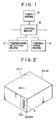
- Figure 1 is a block diagram showing the basic configuration of an embodiment of the invention.
- Figure 2 is a perspective view showing an embodiment of an bubble-jet type ink jet cartridge to which the invention can apply.
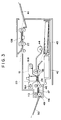
- Figure 3 shows a cross section of the internal configuration of a facsimile system embodying the invention.
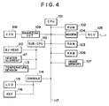
- Figure 4 is a block diagram showing an example of a circuit configuration for a facsimile system embodying the invention.
- Figure 5 is a timing chart showing the operation timing for the first embodiment of the invention.
- Figure 6 is a flowchart showing the control operation for the first embodiment of the invention.
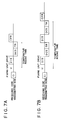
- Figure 7A and 7B are timing charts showing the operation timings for the second embodiment of the invention.
- Figure 8 is a flowchart showing the control operation of the second embodiment of the invention.
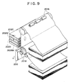
- Figure 9 is a perspective view of the schematic configuration of a full-length type ink jet recording apparatus for other embodiment of the invention.
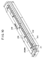
- Figure 10 is a perspective view of the recording head in Figure 9.
- FIG. 1 is a block diagram showing the basic concept for an embodiment of the invention.
- A represents a heat fusing means which is installed in a facsimile system including an ink jet recording apparatus as a recorder and uses heat to fuse ink on a recorded material (generally, paper) recorded by the ink jet recording apparatus.
- B is a control means which actuates the heat fusing means A with reception of a call signal.
- C is a temperature detecting means which detects the temperature of the heat fusing means A.
- D is a counting means which counts a given time when the heat fusing means is actuated.
- the control means B starts receiving image data when the detected value of the temperature detecting means C has reached a given fusing temperature. If the detected value of the temperature detecting means C does not reach the given fusing temperature before the counting means D finishes counting a certain time, the control means B releases the circuit and outputs an error alarm.
- Figure 2 and 3 show an example of a configuration of an ink jet printer or an optimal recorder for a facsimile system in which the invention is implemented.
- 20 is an ink jet head (recording head) which uses bubbles generated with heat energy to discharge ink onto a recording sheet.
- 21 is an ink jet cartridge (IJC) which is freely detachable and equipped with a tank 10IT which is united with the ink jet head (IJH) and supplies ink to the ink jet head (IJH).
- IJRA represents the main unit of an ink jet recording apparatus.
- the ink jet cartridge 21 is shaped, as seen in the perspective view of Figure 2, in such a way that the distal portion of the ink jet head 20 is slightly protruding from the front surface of the ink tank 10.
- the ink jet head cartridge 21 is fixed to a carriage placed on the main unit of the ink jet recording apparatus IJRA which will be described later.
- the disposable ink jet head cartridge 21 is detachable from the carriage.
- the first ink tank 10 contains ink to be supplied to the ink jet head 20 and comprises an ink absorber, a container used to insert the ink absorber, and a cover member for sealing the container (not illustrated).
- the ink tank is filled with ink and supplies ink to the ink jet head when ink is discharged.
- a front plate 4 is made of a resin such as polysulfone, polyether sulfone, polyphenylene oxide and polypropylene, which are excellent in ink resistance.
- the ink jet cartridge 21 having the aforesaid configuration is mounted on the carriage HC of the ink jet recording apparatus IJRA according to the procedure described below, and is freely detachable. With a given recording signal provided, the relative movements of the carriage HC and a recorded material are controlled to form a required recording image.
- Figure 3 shows a cross section of the mechanical configuration of a facsimile system related to an embodiment of the invention.
- 108 represents a close-contact image sensor, which reads an original transported to a given position by feed rollers 22, then converts the information into electric signals. The converted electric signals are processed and transmitted as described later.
- 41 is an original tray for storing originals.
- the 42 represents a recording sheet cassette for storing recording sheets (43).
- the recording sheets are supplied one by one by a separation roller 44, then sent to a platen 24 or a recording position by feed rollers 45.
- FIG. 20 represents, as shown Figure 2, an ink jet head (recording head) of an ink jet head cartridge IJC, which is equipped with a group of nozzles 13a which discharge ink from the opposite side of the recording face of a recording sheet fed onto the platen 24.
- 16 is a carriage HC for supporting the recording head 20.
- the carriage 16 is slidably mounted on two mutually parallel guide shafts 16A and 16B.
- the driving force of a drive motor (not illustrated) is transmitted via a belt (not illustrated). Then, the recording head 20 reciprocates over the entire width of a recording sheet, discharges ink onto the recording sheet to produce an image corresponding to received image data.
- a head restoration unit (not illustrated) is installed at one end of the moving path of the recording head 20, or a position opposed to a home position.
- the head restoration unit is actuated to cap the recording head 20.
- an absorbing means incorporated in the head restoration unit for example, an absorption pump
- absorbs ink or a pressing means incorporated in the ink supply path supplies ink to the recording head 20 using pressure.
- ink is discharged forcibly from orifices so that ink with increased viscosity inside of the orifices can be removed.
- This discharge restoration is performed when the power supply is turned ON, the recording head is replaced, or a recording operation is not done for more than a given time.
- the capping operation performed at the end of recording protects the recording heads.
- a recorded sheet which has undergone the aforesaid recording operation is sent to a position of a fusing heat plate 48 whose temperature is raised to a given fusing temperature by a heating element (heater) 47, and applied ink is rapidly fused onto the sheet with heat of the fusing heat plate 48.
- the recording sheet which has undergone a fusing operation is discharged onto a discharge tray 50 by discharge roller 49.
- a fusing unit can be formed in the same manner even in a facsimile system using rolled paper.
- 113 is a sensor for detecting the temperature of the heat fusing plate 48.
- a heat plate is used as a fusing unit instead of a roller. Therefore, a recording sheet which has not been fused can be fused in a non-contact state. This prevents distortion of a recording image or ink stains.
- FIG. 4 shows an example of a circuit configuration for a facsimile system embodying the invention.
- 101 represents a main CPU or central processing unit including a microcomputer which controls the entire system to transmit or receive data via a bus 117.
- 102 is a read only memory (ROM) incorporated in the CPU 101 which contains the contents of various control procedures (programs) as shown in Figures 6 and 8.
- 103 is a work random access memory (RAM) the CPU 101 uses for a job related to a counter or a register.
- 104 is a modulator-demodulator (modem) for data transmission, and 105, a network contol unit (NCU) to be connected to the modem 104.
- 106 is a registration RAM to be connected to a public telephone line via the NCU 104, wherein telephone numbers and abbreviations are registered.
- 107 is an image RAM (DRAM) which temporarily stores image data.
- DRAM image RAM
- 108 is a charge coupled device (CCD) serving as an imaging means in an original reader, which converts an original image formed through a rod lens or other image formation lens into electric signals.
- 109 is a binary coding circuit which binary-codes output signals of the CCD 108.
- 20 is a recording head in a recorder.
- An ink jet recording apparatus of the type shown in Figures 2 and 3 is used as the recorder in this embodiment.
- 110 is a sub CPU which controls a bubble jet head (BJ head) 20 in the recorder, a heating element 47, drive motors 17 to 22, and a temperature sensor 113 according to a control signal sent from the CPU 101.
- the sub CPU 110 incorporates a ROM which contains control programs for image recording.
- 114 is a console having a keyboard. On the operator panel, a liquid crystal display (LCD) 115 and various keys 116 are arranged.
- LCD liquid crystal display
- a call signal (Ci signal with 16 Hz)
- a given control signal is transmitted to CPU 110 so as to actuate a heating element 47 of a fusing unit (to start energizing and heating the element).
- a response signal or a digital identification (DIS)) signal which serves to transmit the functions of a local system to a remote system is not transmitted until a signal indicating at the temperature of the fusing heat plate 48 in the fusing unit has reached a given fusing temperature is received from the CPU 110.
- step S1 when a Ci signal is detected (step S1), an internal timer T is set to a given permissible temperature rising time (or rising time) N (for example; 10 to 15 seconds). The internal timer T starts counting the time in decrements (step S2). Then, a heating element 47 in a fusing unit (step S3) is energized.
- N permissible temperature rising time
- step S5 if the detected value of a temperature sensor 113 provided to a fusing heat plate 48 in the fusing unit reaches a given fusing temperature (step S5) before the timer T value comes to 0 (step S4), a circuit is picked up to transmit a DIS signal, then a normal receive operation starts (steps S6 and S7). This enables reception and recording of image data.
- step S4 if the timer T value comes to 0 with the detected value of the temperature sensor 113 unreached the given fusing temperature (step S4), it is recognized as a fusing unit failure.
- An error alarm indicating that an error occurs in the fusing unit is output to a display 115 on a console 114.
- the circuit is released to suspend the receive operation (step S8).
- a buzzer sounds an alarm or that a receiving side transmits a signal indicating the occurrence of an error to a transmitting side.
- a given lamp may be blinked instead of displaying an error message.
- the rising time for a heat fusing unit can be ensured.
- the temperature of the heat fusing unit has already risen to a sufficient temperature for fusing. This eliminates ink stains due to a fusing failure. In addition, an error in the fusing unit can be surely informed.
- Figures 7A and 7B show the control operation of the second embodiment of the invention.
- a fusing unit is actuated with detection of an automatically-received call signal (Ci signal with 16 Hz) in the same manner as that for the first embodiment.
- a DIS signal or a response signal (which selects a communicative mode based on the contents of DIS and instructs reception) is transmitted according to a digital instruction (DCS) signal even while the temperature of the fusing unit is rising.
- DCS digital instruction
- CFR reception ready verification
- TR represents a training signal to be trasmitted from a transmitting side after the DCS signal.
- Figure 7A is a timing chart for a short rising time in summer, and Figure 7B, that for a long rising time in winter.
- a Ci signal when a Ci signal is detected, a circuit is fetched (steps S11 and S12) and an internal timer T is set to a given permissible temperature rising time (or rising time) N. Then, the internal timer T starts counting in decrements (step S13). After that, a heating element 47 in the fusing unit is actuated (step S14).
- a DIS signal is transmitted (step S15).
- a DCS signal received step S16
- step S17 After that, if the temperature of a fusing heat plate 48 in the fusing unit has reached the given temperature (step S17) before the timer T value comes to 0, a CFR signal indicating that image signal reception is ready is transmitted (step S19) to start a normal receive operation (step S20). This enables reception and recording of image data.
- step S18 if the timer T value comes to 0 with the detected value of the temperature sensor 113 unreached the given fusing temperature (step S18), the circuit is released (step S21) and an error alarm signal indicating that an error occurs in the fusing unit is output to a display 115 on a console 114 (step S22).
- a buzzer sounds an alarm or that a receiving side transmits a signal indicating the occurrence of an error to a transmitting side.
- the second embodiment ensures an extra time, because the temperature of a fusing unit need not be raised until an image signal reaches.
- a heat fusing unit may be actuated with reception of a Ci signal, and receive operation may be started in a sufficient given time.
- the receive operation start time may be delayed unnecessarily. This is not preferable from the viewpoint of a quick reception. If the heat fusing unit malfunctions, a recording failure may occur.
- the present invention is applicable not only to a serial printer mentioned above but also to a facsimile system equipped with an ink jet recording apparatus having a full-length type recording head which has a width equivalent to that of a maximum recording medium on which a recording unit can record data as shown in Figures 9 and 10.
- 201A and 201B are a pair of rollers installed for carrying a recording medium R in arrow-marked sub-scanning direction Vs.
- 202BK, 202Y, 202M, and 202C are fully multipurpose type recording heads for recording the colors of black, yellow, magenta, and cyan, whose nozzles are arranged over the whole width of the recording medium R.
- the recording heads 202BK, 202Y, 202M, and 202C are arranged in that order from the upstream in recording medium transporting direction.
- the 200 is a restoration mechanism, which substitutes for the recording medium R and are opposed to the recording heads 202B to 202C during restoration of ink discharge (a discharge restore operation).
- preheating is done at a proper timing, and thereby the number of discharge restore operations activated can be diminished remarkably.
- Figures 9 and 10 show an appearance of the recording heads 202BK to 202C.
- 210 is ink orifices, and 211, an ink supply tube.
- 212 represents multiple IC circuits (drive circuits) for driving electric heat conversion elements.
- 213 and 214 are terminals.
- the invention is also applicable to a facsimile system having a recorder of a piezoelectric type ink jet recording apparatus which uses a piezoelectric element as an ink discharge energy source.
- the present invention brings about excellent effects when implimented in a recording head or recording apparatus, especially, of a bubble jet method among all the ink jet recording methods.
- the bubble jet method permits high-density and high-definition recording.
- liquid ink is discharged via discharge orifices. Then, at least one droplet is formed.
- the drive signal has a pulse waveform
- the bubbles grow and contract at regular intervals. Liquid ink can be discharged precisely in response to the drive signal.
- the drive signal of a pulse waveform described in the specification of U.S. Patent No. 4463359 or No. 4345262 would be suitable. If the conditions written in the specification of U.S. Patent No. 4313124 related to the temperature rise rate of the thermal action surface are met, more excellent recording can be done.
- the configuration of a recording head As for the configuration of a recording head, orifices, a liquid path, and electric heat conversion elements (linear liquid path or perpendicular liquid path) may be combined as disclosed in the aforesaid specifications.
- the invention will prove effective when implemented in the configuration disclosed in Japanese Patent Application Laid-open No. 59-123670 in which a shared slit is arranged as an orifice for multiple electric heat conversion elements, or that disclosed in Japanese Patent Application Laid-open No. 59-138461 in which an orifice for absorbing pressure waves of heat energy is opposed to a discharge unit. That is to say, the recording head can assume any shape.
- the invention is effectively applicable to a full-length type recording head having a length covering the maximum width of a recording medium on which a recording unit can record data.
- Such a recording head may have a configuration in which multiple recording heads are combined to cover the length or multiple recording head are united as a single recording head.
- the invention will prove effective when implemented in a chip type recording head among the aforesaid serial type recording heads which can be electrically connected to the main unit of a system and supplied ink from the main unit when the recording head is mounted to the main unit of the system, and which is freely exchangeable. Using a recording head of a united cartridge type, the invention will prove effective.
- a restoration means for a recording head and an auxiliary support means are included in the configuration of a recording unit of the invention, the effects of the invention will be further enhanced. Specifically, the combination of a capping means or a cleaning means for a recording head, a pressing or absorbing means, electric heat conversion elements, other heating elements, or an auxiliary heating means or a combination of the electric heat conversion elements and other heating elements, or an auxiliary discharge mode in which ink is discharged for other purpose except recording will contribute to more stable recording.
- a heat fusing means for fusing ink is actuated with reception of a call signal, the time for raising the temperature of the heat fusing means before the start of printing can be ensured.
- a facsimile system or other image communication system which permits received images without ink stains can be provided.
- a receiving operation of image data is started after it is confirmed that the temperature of the heat fusing means has reached a given fusing temperature. Therefore, the temperature of the heat fusing means has already risen to a sufficient temperature for fusing at the start of printing. This guarantees high-quality image recording without causing a fusing failure.
Landscapes
- Engineering & Computer Science (AREA)
- Multimedia (AREA)
- Signal Processing (AREA)
- Human Computer Interaction (AREA)
- Ink Jet (AREA)
- Fax Reproducing Arrangements (AREA)
- Facsimile Transmission Control (AREA)
- Facsimile Heads (AREA)
Applications Claiming Priority (2)
| Application Number | Priority Date | Filing Date | Title |
|---|---|---|---|
| JP41059/90 | 1990-02-23 | ||
| JP2041059A JPH03244545A (ja) | 1990-02-23 | 1990-02-23 | ファクシミリ装置 |
Publications (3)
| Publication Number | Publication Date |
|---|---|
| EP0443872A2 EP0443872A2 (en) | 1991-08-28 |
| EP0443872A3 EP0443872A3 (en) | 1991-10-23 |
| EP0443872B1 true EP0443872B1 (en) | 1996-01-03 |
Family
ID=12597848
Family Applications (1)
| Application Number | Title | Priority Date | Filing Date |
|---|---|---|---|
| EP91301439A Expired - Lifetime EP0443872B1 (en) | 1990-02-23 | 1991-02-22 | Image communication system |
Country Status (4)
| Country | Link |
|---|---|
| EP (1) | EP0443872B1 (ja) |
| JP (1) | JPH03244545A (ja) |
| DE (1) | DE69115951T2 (ja) |
| ES (1) | ES2084098T3 (ja) |
Families Citing this family (2)
| Publication number | Priority date | Publication date | Assignee | Title |
|---|---|---|---|---|
| SE506534C2 (sv) * | 1995-06-15 | 1998-01-12 | Ericsson Telefon Ab L M | Sätt att bestämma innehåll i restaureringslogg |
| JP2002019260A (ja) | 2000-07-04 | 2002-01-23 | Seiko Epson Corp | 記録方法 |
Family Cites Families (9)
| Publication number | Priority date | Publication date | Assignee | Title |
|---|---|---|---|---|
| US2454247A (en) * | 1945-12-28 | 1948-11-16 | Rca Corp | Facsimile recording apparatus |
| JPS5668061A (en) * | 1979-11-08 | 1981-06-08 | Iwatsu Electric Co Ltd | Facsimile receiving device |
| JPS56151578A (en) * | 1980-04-28 | 1981-11-24 | Sanyo Electric Co Ltd | Thermosensitive recorder |
| US4760462A (en) * | 1981-03-26 | 1988-07-26 | Ricoh Company, Ltd. | Heat sensitive recording system in facsimile communication |
| JPS57212866A (en) * | 1981-06-24 | 1982-12-27 | Ricoh Co Ltd | Facsimile recording and display device |
| DE3423072C2 (de) * | 1983-06-23 | 1986-11-20 | Nippon Telegraph And Telephone Corp., Tokio/Tokyo | Thermodruckvorrichtung |
| JPS63134289A (ja) * | 1986-11-26 | 1988-06-06 | Canon Inc | 熱転写記録方法 |
| EP0294793B1 (en) * | 1987-06-12 | 1996-10-09 | Canon Kabushiki Kaisha | Recording apparatus |
| JPH01272480A (ja) * | 1988-04-25 | 1989-10-31 | Ricoh Co Ltd | 記録装置 |
-
1990
- 1990-02-23 JP JP2041059A patent/JPH03244545A/ja active Pending
-
1991
- 1991-02-22 DE DE69115951T patent/DE69115951T2/de not_active Expired - Fee Related
- 1991-02-22 EP EP91301439A patent/EP0443872B1/en not_active Expired - Lifetime
- 1991-02-22 ES ES91301439T patent/ES2084098T3/es not_active Expired - Lifetime
Also Published As
| Publication number | Publication date |
|---|---|
| ES2084098T3 (es) | 1996-05-01 |
| DE69115951T2 (de) | 1996-05-30 |
| JPH03244545A (ja) | 1991-10-31 |
| DE69115951D1 (de) | 1996-02-15 |
| EP0443872A3 (en) | 1991-10-23 |
| EP0443872A2 (en) | 1991-08-28 |
Similar Documents
| Publication | Publication Date | Title |
|---|---|---|
| US5631674A (en) | Recording apparatus | |
| US6123403A (en) | Image communicating apparatus controlling data reception based on number of non-discharge condition | |
| JP3368066B2 (ja) | 画像記録装置および画像記録方法 | |
| US5249062A (en) | Image communication using ink jet recorder with heat fusing device | |
| US6048045A (en) | Printer and facsimile apparatus that can test for a proper functioning ink jet nozzle without printing a test pattern | |
| EP0443808B1 (en) | Image communicating apparatus | |
| US5689289A (en) | Image recording apparatus | |
| EP0401024B1 (en) | Image communication apparatus | |
| US5251040A (en) | Image communication apparatus having ink jet recorder with timer for controlling reception of successive pages of image data | |
| US5175566A (en) | Image communicating apparatus with ink jet printer having controlled capping operation | |
| EP0443872B1 (en) | Image communication system | |
| EP0443716B1 (en) | Image communication apparatus | |
| EP0443247B1 (en) | Image communicating apparatus | |
| US5777633A (en) | Image communicating apparatus with ink jet printer having controlled capping operation | |
| EP0616896B1 (en) | Image recording apparatus | |
| EP0443833B1 (en) | Image communication apparatus | |
| JP2829771B2 (ja) | インクジェット記録装置の回復制御方法 | |
| JP2786295B2 (ja) | ファクシミリ装置 | |
| US6106086A (en) | Facsimile apparatus | |
| JPH03234621A (ja) | 記録装置 | |
| JP2818026B2 (ja) | インクジェット記録装置 | |
| JPH08181803A (ja) | インクジェットファクシミリ装置 | |
| JPH05336299A (ja) | 画像形成方法及び装置 | |
| JP2004202781A (ja) | インクタンク交換の検出方法 | |
| JPH07314838A (ja) | 記録装置 |
Legal Events
| Date | Code | Title | Description |
|---|---|---|---|
| PUAI | Public reference made under article 153(3) epc to a published international application that has entered the european phase |
Free format text: ORIGINAL CODE: 0009012 |
|
| AK | Designated contracting states |
Kind code of ref document: A2 Designated state(s): DE ES FR GB IT |
|
| PUAL | Search report despatched |
Free format text: ORIGINAL CODE: 0009013 |
|
| AK | Designated contracting states |
Kind code of ref document: A3 Designated state(s): DE ES FR GB IT |
|
| 17P | Request for examination filed |
Effective date: 19920316 |
|
| 17Q | First examination report despatched |
Effective date: 19931026 |
|
| GRAA | (expected) grant |
Free format text: ORIGINAL CODE: 0009210 |
|
| AK | Designated contracting states |
Kind code of ref document: B1 Designated state(s): DE ES FR GB IT |
|
| REF | Corresponds to: |
Ref document number: 69115951 Country of ref document: DE Date of ref document: 19960215 |
|
| ET | Fr: translation filed | ||
| ITF | It: translation for a ep patent filed |
Owner name: SOCIETA' ITALIANA BREVETTI S.P.A. |
|
| REG | Reference to a national code |
Ref country code: ES Ref legal event code: FG2A Ref document number: 2084098 Country of ref document: ES Kind code of ref document: T3 |
|
| PLBE | No opposition filed within time limit |
Free format text: ORIGINAL CODE: 0009261 |
|
| STAA | Information on the status of an ep patent application or granted ep patent |
Free format text: STATUS: NO OPPOSITION FILED WITHIN TIME LIMIT |
|
| 26N | No opposition filed | ||
| REG | Reference to a national code |
Ref country code: GB Ref legal event code: IF02 |
|
| PGFP | Annual fee paid to national office [announced via postgrant information from national office to epo] |
Ref country code: ES Payment date: 20040203 Year of fee payment: 14 |
|
| PGFP | Annual fee paid to national office [announced via postgrant information from national office to epo] |
Ref country code: GB Payment date: 20040209 Year of fee payment: 14 |
|
| PGFP | Annual fee paid to national office [announced via postgrant information from national office to epo] |
Ref country code: FR Payment date: 20040223 Year of fee payment: 14 |
|
| PGFP | Annual fee paid to national office [announced via postgrant information from national office to epo] |
Ref country code: DE Payment date: 20040225 Year of fee payment: 14 |
|
| PG25 | Lapsed in a contracting state [announced via postgrant information from national office to epo] |
Ref country code: IT Free format text: LAPSE BECAUSE OF NON-PAYMENT OF DUE FEES Effective date: 20050222 Ref country code: GB Free format text: LAPSE BECAUSE OF NON-PAYMENT OF DUE FEES Effective date: 20050222 |
|
| PG25 | Lapsed in a contracting state [announced via postgrant information from national office to epo] |
Ref country code: ES Free format text: LAPSE BECAUSE OF NON-PAYMENT OF DUE FEES Effective date: 20050223 |
|
| PG25 | Lapsed in a contracting state [announced via postgrant information from national office to epo] |
Ref country code: DE Free format text: LAPSE BECAUSE OF NON-PAYMENT OF DUE FEES Effective date: 20050901 |
|
| GBPC | Gb: european patent ceased through non-payment of renewal fee |
Effective date: 20050221 |
|
| PG25 | Lapsed in a contracting state [announced via postgrant information from national office to epo] |
Ref country code: FR Free format text: LAPSE BECAUSE OF NON-PAYMENT OF DUE FEES Effective date: 20051031 |
|
| REG | Reference to a national code |
Ref country code: FR Ref legal event code: ST Effective date: 20051031 |
|
| REG | Reference to a national code |
Ref country code: ES Ref legal event code: FD2A Effective date: 20050223 |