EP0443655A1 - Verbinder zur Kontaktierung von auf Flexfolie befindlichen Leiterbahnen mit entsprechenden leitenden Einsatzstücken - Google Patents
Verbinder zur Kontaktierung von auf Flexfolie befindlichen Leiterbahnen mit entsprechenden leitenden Einsatzstücken Download PDFInfo
- Publication number
- EP0443655A1 EP0443655A1 EP91200249A EP91200249A EP0443655A1 EP 0443655 A1 EP0443655 A1 EP 0443655A1 EP 91200249 A EP91200249 A EP 91200249A EP 91200249 A EP91200249 A EP 91200249A EP 0443655 A1 EP0443655 A1 EP 0443655A1
- Authority
- EP
- European Patent Office
- Prior art keywords
- spring clip
- flexfoil
- recess
- connector according
- connector
- Prior art date
- Legal status (The legal status is an assumption and is not a legal conclusion. Google has not performed a legal analysis and makes no representation as to the accuracy of the status listed.)
- Granted
Links
Images


Classifications
-
- H—ELECTRICITY
- H01—ELECTRIC ELEMENTS
- H01R—ELECTRICALLY-CONDUCTIVE CONNECTIONS; STRUCTURAL ASSOCIATIONS OF A PLURALITY OF MUTUALLY-INSULATED ELECTRICAL CONNECTING ELEMENTS; COUPLING DEVICES; CURRENT COLLECTORS
- H01R27/00—Coupling parts adapted for co-operation with two or more dissimilar counterparts
-
- H—ELECTRICITY
- H01—ELECTRIC ELEMENTS
- H01R—ELECTRICALLY-CONDUCTIVE CONNECTIONS; STRUCTURAL ASSOCIATIONS OF A PLURALITY OF MUTUALLY-INSULATED ELECTRICAL CONNECTING ELEMENTS; COUPLING DEVICES; CURRENT COLLECTORS
- H01R12/00—Structural associations of a plurality of mutually-insulated electrical connecting elements, specially adapted for printed circuits, e.g. printed circuit boards [PCB], flat or ribbon cables, or like generally planar structures, e.g. terminal strips, terminal blocks; Coupling devices specially adapted for printed circuits, flat or ribbon cables, or like generally planar structures; Terminals specially adapted for contact with, or insertion into, printed circuits, flat or ribbon cables, or like generally planar structures
- H01R12/50—Fixed connections
- H01R12/59—Fixed connections for flexible printed circuits, flat or ribbon cables or like structures
- H01R12/592—Fixed connections for flexible printed circuits, flat or ribbon cables or like structures connections to contact elements
Definitions
- the invention relates to a connector for contacting one or more conductor tracks provided on a flexfoil to corresponding conducting inserts, which connector comprises a body of insulating material, which is provided with at least one insert hole for inserting an insert to be contacted and a recess for receiving at least part of the flexfoil, which recess overlaps the insert hole and is in connection with the insert hole in the region of overlap, as well as a spring clip, in which connector, in the assembled position, the conductor tracks face the associated insert holes and the spring clip, bearing against the side of the flexfoil facing from the conductor tracks, presses the conductor tracks at least partially into the respective insert holes.
- a U-shaped spring clip is also used to press a conductor track against a contact pin.
- the spring clip is arrested in an insert hole wider as to the contact pin.
- the object of the invention is to provide an abovementioned connector in which the spring clip has a simple form.
- the spring clip comprising strips which are provided on both their longitudinal edges with fastening elements engaging in the recess wall.
- This connector has the advantage that, in spite of the simple form of the spring clip, a good contact pressure between the conductor tracks and contact pins is nevertheless achieved. Due to the simple form of the spring clip, it can be produced in an easy way. Moreover, the connector is easy to assemble, that is without special tools.
- the fastening elements of the spring clip comprise resilient fastening lugs extending transversely with respect to the spring clip surface, the distance between the outwardly bent-away, free ends of these lugs being greater than the distance between the recess walls adjacent to these ends and the said recess walls having wall clearances, in which the corresponding lug ends are able to snap into place.
- the fastening elements of the spring clip comprise fastening lugs extending transversely with respect to the spring clip surface, the end faces of which lugs are of a sawtooth-like design and engage in wall clearances of the body recess adjacent to these end faces, which wall clearances are formed by the sawteeth during insertion of the spring clip, the tips of the sawteeth lying in a plane running at an acute angle with respect to the bottom surface of the spring clip.
- the angle is preferably 5°.
- the free end of the spring clip lying above the insert hole is provided with a spring clip end part bent-away in the direction of the insert hole.
- the contact pressure between conductor track and contact pin can be set in an easy way by the degree of bending-away of the spring clip end part. At the same time, it must be ensured that the degree of bending-away is not too great, as otherwise the insertion of the contact pin is made difficult.
- bent-away spring clip end part being followed by a bent-back spring clip end part.
- the body is provided on the insert side of the insert hole with an inwardly protruding bearing lug, against which the free end of the spring clip, lying above the insert hole, bears with prestress.
- the contact pressure is further improved without making the insertion of the contact pin difficult, while the setting of the contact pressure can be made in an easy way by appropriate choice of the prestress.
- the walls of the recess of the body adjacent to the longitudinal edges of the flexfoil are provided above the insert hole with slits for receiving the flexfoil projections provided at the free end of the flexfoil, running transversely with respect to the latter and sideways. These flexfoil projections are secured in the respective slits, thereby preventing the flexfoil being pushed away during the insertion of contact pins.
- this flexfoil extends until between the spring clip end part and the bearing lug, this flexfoil is securely held in its position in an advantageous way, so that the said strip is not pushed away by insertion of the contact pin.
- the pushing-away of the flexfoil is prevented in an even better way if the spring clip end part lying above the insert hole has at its free end a narrower engaging projection for engaging in respective holes provided in the part to be introduced of the flexfoil.
- FIGs 1 and 2 a first embodiment of a connector according to the invention is presented.
- the base part of the connector is a body 1, produced from insulating material, in which a recess 2 for receiving the end part of a flexfoil 3 is provided.
- a recess 2 for receiving the end part of a flexfoil 3 is provided on the underside of the flexfoil 3 .
- the conductor tracks 4 are provided on the underside of the flexfoil 3.
- the body 1 also has two insert holes 5 for the insertion of conducting inserts to be contacted, which inserts are in this design formed by two contact pins of rectangular cross-section (not shown).
- the insert holes 5 run partially below the recess 2 and are consequently partially overlapped by this recess. In the region of overlap, the recess 2 goes over to the insert holes 5.
- the flexfoil 3 is securely held in the recess 2 by means of a spring clip 6 and in particular the conducting tracks 4 in the region of overlap of recess 2 and the insert holes 5 are pushed until approximately in the said insert holes.
- the contact pins are inserted in the respective insert holes 5, these pins are contacted to the corresponding conductor tracks by the contact pressure produced by the bent-out spring clip.
- the spring clip 6 comprises a lower surface 7, from the edges of which two fastening lugs 8 extend virtually transversely with respect to the said surface 7.
- the free ends of the fastening lugs 8 are to some extent bent away outwards, to be precise protrude past the surface running transversely with respect to the lower surface 7 and through the edges.
- the distance between the end edges of the fastening lugs 8 is intended to be greater than that between recess walls 2 adjacent to these ends.
- These recess walls have wall clearances 9, only one of which is visible in Figure 1. In the assembled state of the connector, the free ends of the fastening lugs snap into the corresponding said wall clearances 9. Consequently, the spring clip 7 is securely fitted together with the flexfoil 3 in the recess 2.
- the spring clip 6 is preferably provided with two spring clip legs 10, in order to ensure an appropriate contact pressure for each contact between the conductor tracks 4 and the contact pins.
- the end of the spring clip legs 10 has a part which is bent down and a part which is bent back again. This design of the spring clip end part makes the insertion of the contact pins easy.
- the front wall 11 of the recess 2 is provided with an inwardly protruding bearing lug 12. The end edge part of the curved part of the spring clip 6 rests on this bearing lug 12, preferably under a predetermined prestress.
- the length of the curved part of the spring clip 6 and its curvature are adapted in such a way to the height of the bearing lug 12 that the conductor tracks 4 lying on the flexfoil 3 are pushed until approximately in the insert holes 5.
- the contact pressure between the conductor tracks and the inserted contact pins has been further improved, while a very easy insertion of these contact pins nevertheless remains possible.
- a further setting of the contact pressure dependent on the bearing prestress of the spring clip 6 can be carried out in an easy way.
- the free end of the flexfoil is provided with transversely running projections 3', 3'', which are secured in the slits 2' and 2'', as a result of which the free end of the flexfoil is not easily pushed too far into the insert hole 5. Moreover, it is also prevented that the end of the flexfoil is pushed away during insertion of the pin.
- the flexfoil end part is preferably introduced so far into the recess 2 that at least the free edge of this flexfoil 3 is clamped between the end edge of the spring clip 6 and the bearing surface of the bearing lug 12. This prevents the flexfoil 3 from being pushed further by insertion of the contact pins.
- FIG 3 a four-position connector is illustrated, the body 1 of which is provided with two recesses 2, of which only the uppermost recess is visible in Figure 3. However, both recesses 2 are visible in the cross-section shown in Figure 4.
- the body 1 of the design shown in Figures 3 and 4 has two pairs of insert holes 5 lying next to each other.
- a flexfoil 3 which has two free end parts 13 and 14, joined by a connecting part 15.
- 4 conductor tracks of the flexfoil 3 are contacted to 4 contact pins (not shown).
- the said end parts 13 and 14 are securely held in the corresponding recesses 2 by the respective spring clips 6, while the conductor tracks are pushed until approximately in the insert holes 5.
- the spring clip 6 is of a similar design to that of Figures 1 and 2.
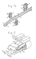
- a flexfoil 3 is shown, using for example two two-position connectors and one four-position connector, the bodies of which are indicated by 1. It is clear that, depending on the number of conductor tracks 4, the number of connectors and the pattern of the conductor tracks, any number of connections between the respective conductor tracks and any number of contact pins can be produced.
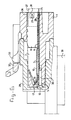
- FIG. 6 and 7 A further development of the connector according to the invention is shown in Figures 6 and 7, to be precise a further two-position connector.
- This connector again comprises a body 1 in which two insert holes 5 are provided.
- a different method of fastening the spring clip 6 is used in the case of the connector according to Figures 6, 7 and 8.
- the end face of the fastening lugs 8 formed on the spring clip 6 and bent away are of a sawtooth-like design. If the spring clip 6 is inserted into the recess 2 and pushed, the sawteeth engage in the upper wall 38 of the recess 2 and push themselves into this wall. As a result, the spring clip 6 is securely held in its end position.
- the conductor tracks 4 of the flexfoil 3 are pushed down by the spring clip 6 until approximately in the insert holes 5.
- the spring clip legs 10 are provided at their free ends with narrower engaging projections 17, which engage in the holes 16 made in flexfoil 3 and consequently secure the flexfoil also at the free end, thus preventing the flexfoil from being slipping away during insertion of the contact pins 30, 31.
- Bearing lugs 12 for the free ends of the spring clip legs 10 are also provided in the design of the connector shown in Figures 6 and 7. In this design, the end of the flexfoil is securely held both by its clamping between the free ends of the spring clip legs and the bearing surface of the bearing lugs 12 and by the engaging of the projections 17 in the holes 16 in the recess 2.
- the body 2 is in each case also provided with an additional pull relief for the flexfoil 3.
- the bottom of the recess 2 is provided with two pull-relief pins 18 and 19, which pins fit into corresponding holes 20 and 21 when the connector is in the assembled state.
- the said pins also run through holes 22 provided in the spring clips 6. It is clear that the connector according to Figures 3 and 4 has four pull-relief pins.
- the pull relief of the flexfoil 3 is achieved in the case of the version shown in Figures 6 and 7 by means of the projections 23, 24 and 25, of which 24 is not visible, in the fastening lugs 8 or bottom surface of the spring clip 6, which projections 23 and 24 engage in corresponding holes 26 in parts 27 of the flexfoil 3 which are bent away in the direction of the lugs 8.
- the part 27 of the flexfoil 3 is thus bent up transversely with respect to the surface of the flexfoil.
- the projection 25 engages in the hole 28.
- FIG 6 there is also depicted a counter-connector 29, interacting with the body 1 of the connector according to the invention.
- the contact pins 30 and 31 are located in a recess, in which the body 1 can be inserted.
- the connector and the counter-connector are provided with intermeshing locking elements 32 and 33.
- the counter-connector 29 is connected to a coil 39.
- the bodies 1 according to Figures 1-5 have longitudinal webs 35, which are provided with locking projections 34 and interact with corresponding grooves in the counter-connector.
- FIG 8 there is also drawn an embodiment of a connector according to the invention using sealing elements 36 and 37.
- the other component parts of this connector 1 and counter-connector 29 are similar to those of the connectors and counter-connectors of Figures 6 and 7.
Applications Claiming Priority (2)
| Application Number | Priority Date | Filing Date | Title |
|---|---|---|---|
| DE9002181U | 1990-02-23 | ||
| DE9002181U DE9002181U1 (de) | 1990-02-23 | 1990-02-23 |
Publications (2)
| Publication Number | Publication Date |
|---|---|
| EP0443655A1 true EP0443655A1 (de) | 1991-08-28 |
| EP0443655B1 EP0443655B1 (de) | 1995-11-15 |
Family
ID=6851334
Family Applications (1)
| Application Number | Title | Priority Date | Filing Date |
|---|---|---|---|
| EP91200249A Expired - Lifetime EP0443655B1 (de) | 1990-02-23 | 1991-02-06 | Verbinder zur Kontaktierung von auf Flexfolie befindlichen Leiterbahnen mit entsprechenden leitenden Einsatzstücken |
Country Status (10)
| Country | Link |
|---|---|
| US (1) | US5057037A (de) |
| EP (1) | EP0443655B1 (de) |
| JP (1) | JP3061872B2 (de) |
| KR (1) | KR0117073Y1 (de) |
| AT (1) | ATE130468T1 (de) |
| AU (1) | AU7117091A (de) |
| BR (1) | BR9100722A (de) |
| CA (1) | CA2036227A1 (de) |
| DE (2) | DE9002181U1 (de) |
| HK (1) | HK86896A (de) |
Cited By (7)
| Publication number | Priority date | Publication date | Assignee | Title |
|---|---|---|---|---|
| DE29605034U1 (de) * | 1996-03-06 | 1996-05-15 | Petri Ag | Steckverbinder |
| WO1997015965A1 (de) | 1995-10-26 | 1997-05-01 | Reichle + De Massari Ag Elektro-Ingenieure | Verfahren und anordnung zum durchschalten einer mehrzahl voneinander distanzierter elektrischer kontaktstellen |
| DE19633933A1 (de) * | 1996-08-22 | 1998-04-02 | Gore W L & Ass Gmbh | Bandkabel-Verbinder |
| DE19640342A1 (de) * | 1996-09-20 | 1998-04-09 | Siemens Ag | Flachbandleitung mit Stecker als Teil eines elektrischen Netzes |
| DE10006112A1 (de) * | 2000-02-11 | 2001-08-16 | Draexlmaier Lisa Gmbh | Verbinder für Folienleiter |
| DE10250933B3 (de) * | 2002-10-31 | 2004-08-12 | Fci | Verbinderanordnung zwischen einem Flex-Flachbandkabel und einer elektrischen Leiterplatte |
| US7238032B2 (en) | 2003-10-29 | 2007-07-03 | Fci | Connector arrangement between a flat flex cable and a component |
Families Citing this family (7)
| Publication number | Priority date | Publication date | Assignee | Title |
|---|---|---|---|---|
| DE19832012B4 (de) * | 1998-07-16 | 2006-01-12 | Leopold Kostal Gmbh & Co. Kg | Flachbandleiter mit einer Abzweig- und/oder Reparaturstelle sowie Verfahren zur Herstellung einer Abzweig- und/oder Reparaturstelle an einem derartigen Flachbandleiter |
| DE19832011B4 (de) * | 1998-07-16 | 2005-12-22 | Leopold Kostal Gmbh & Co. Kg | Flachbandleitung mit einem zum lösbaren Verbinden vorgesehenen Anschlußbereich |
| EP2057719A2 (de) * | 2006-09-01 | 2009-05-13 | Reichle & De-Massari AG | Adapter und steckverbindungssystem |
| GB201515029D0 (en) * | 2015-08-24 | 2015-10-07 | Sfd Systems Ltd | Connector system |
| JP6968060B2 (ja) * | 2016-05-23 | 2021-11-17 | 古河電気工業株式会社 | フレキシブルフラットケーブル接続具、フレキシブルフラットケーブル接続構造体及び回転コネクタ装置 |
| US10931048B2 (en) * | 2018-09-24 | 2021-02-23 | Apple Inc. | Decoupled spring and electrical path in connector interface |
| CN113922115B (zh) * | 2020-07-07 | 2024-03-08 | 莫仕连接器(成都)有限公司 | 电连接器 |
Citations (2)
| Publication number | Priority date | Publication date | Assignee | Title |
|---|---|---|---|---|
| US3887260A (en) * | 1972-06-16 | 1975-06-03 | Guiseppe Codrino | Multiple coupling connector for electrical connection between flexible ribbon-like conductors and circular cross-section cables |
| EP0339701A1 (de) * | 1988-03-31 | 1989-11-02 | Connector Systems Technology N.V. | Biegsame Schaltung und Verbinder |
Family Cites Families (1)
| Publication number | Priority date | Publication date | Assignee | Title |
|---|---|---|---|---|
| US3983745A (en) * | 1975-08-08 | 1976-10-05 | Mts Systems Corporation | Test specimen crack correlator |
-
1990
- 1990-02-23 DE DE9002181U patent/DE9002181U1/de not_active Expired - Lifetime
-
1991
- 1991-01-22 US US07/644,386 patent/US5057037A/en not_active Expired - Fee Related
- 1991-02-06 EP EP91200249A patent/EP0443655B1/de not_active Expired - Lifetime
- 1991-02-06 DE DE69114542T patent/DE69114542T2/de not_active Expired - Fee Related
- 1991-02-06 AT AT91200249T patent/ATE130468T1/de not_active IP Right Cessation
- 1991-02-13 CA CA002036227A patent/CA2036227A1/en not_active Abandoned
- 1991-02-19 AU AU71170/91A patent/AU7117091A/en not_active Abandoned
- 1991-02-22 BR BR919100722A patent/BR9100722A/pt unknown
- 1991-02-22 KR KR2019910002525U patent/KR0117073Y1/ko not_active IP Right Cessation
- 1991-02-25 JP JP3030225A patent/JP3061872B2/ja not_active Expired - Lifetime
-
1996
- 1996-05-16 HK HK86896A patent/HK86896A/xx not_active IP Right Cessation
Patent Citations (2)
| Publication number | Priority date | Publication date | Assignee | Title |
|---|---|---|---|---|
| US3887260A (en) * | 1972-06-16 | 1975-06-03 | Guiseppe Codrino | Multiple coupling connector for electrical connection between flexible ribbon-like conductors and circular cross-section cables |
| EP0339701A1 (de) * | 1988-03-31 | 1989-11-02 | Connector Systems Technology N.V. | Biegsame Schaltung und Verbinder |
Cited By (10)
| Publication number | Priority date | Publication date | Assignee | Title |
|---|---|---|---|---|
| WO1997015965A1 (de) | 1995-10-26 | 1997-05-01 | Reichle + De Massari Ag Elektro-Ingenieure | Verfahren und anordnung zum durchschalten einer mehrzahl voneinander distanzierter elektrischer kontaktstellen |
| DE29605034U1 (de) * | 1996-03-06 | 1996-05-15 | Petri Ag | Steckverbinder |
| DE19633933A1 (de) * | 1996-08-22 | 1998-04-02 | Gore W L & Ass Gmbh | Bandkabel-Verbinder |
| DE19640342A1 (de) * | 1996-09-20 | 1998-04-09 | Siemens Ag | Flachbandleitung mit Stecker als Teil eines elektrischen Netzes |
| DE19640342C2 (de) * | 1996-09-20 | 2001-05-23 | Siemens Ag | Flachbandleitung mit Stecker als Teil eines elektrischen Netzes |
| DE10006112A1 (de) * | 2000-02-11 | 2001-08-16 | Draexlmaier Lisa Gmbh | Verbinder für Folienleiter |
| DE10250933B3 (de) * | 2002-10-31 | 2004-08-12 | Fci | Verbinderanordnung zwischen einem Flex-Flachbandkabel und einer elektrischen Leiterplatte |
| US7144256B2 (en) | 2002-10-31 | 2006-12-05 | Fci | Connector arrangement between a flexible ribbon cable and a component |
| EP1559175B1 (de) * | 2002-10-31 | 2014-09-17 | Delphi International Operations Luxembourg S.à r.l. | Verbinderanordnung zwischen einem flex-flachbandkabel und einer komponente |
| US7238032B2 (en) | 2003-10-29 | 2007-07-03 | Fci | Connector arrangement between a flat flex cable and a component |
Also Published As
| Publication number | Publication date |
|---|---|
| ATE130468T1 (de) | 1995-12-15 |
| DE69114542T2 (de) | 1996-07-11 |
| JP3061872B2 (ja) | 2000-07-10 |
| CA2036227A1 (en) | 1991-08-24 |
| AU7117091A (en) | 1991-08-29 |
| DE9002181U1 (de) | 1990-05-03 |
| KR0117073Y1 (ko) | 1998-06-01 |
| JPH04218282A (ja) | 1992-08-07 |
| KR910019299U (ko) | 1991-11-29 |
| DE69114542D1 (de) | 1995-12-21 |
| US5057037A (en) | 1991-10-15 |
| EP0443655B1 (de) | 1995-11-15 |
| BR9100722A (pt) | 1991-10-29 |
| HK86896A (en) | 1996-05-24 |
Similar Documents
| Publication | Publication Date | Title |
|---|---|---|
| EP0443655B1 (de) | Verbinder zur Kontaktierung von auf Flexfolie befindlichen Leiterbahnen mit entsprechenden leitenden Einsatzstücken | |
| US5577928A (en) | Hermaphroditic electrical contact member | |
| US6592382B2 (en) | Simplified board connector | |
| US5865645A (en) | Angular press-fit plug connector for press-fitting into holes in a printed circuit board | |
| US6036552A (en) | Connector provided with a retainer | |
| EP0269248A1 (de) | Verbinder für flexible Flachschaltungselemente | |
| EP0472006A1 (de) | Elektrischer Steckverbinder mit Mitteln zum Sicherstellen einer zuverlässigen elektrischen Verbindung | |
| US4612602A (en) | Front plate mounting group for a printed circuit board | |
| GB2033676A (en) | Connector structure for flat cable | |
| EP0407864B1 (de) | Randverbinder für gedruckte Leiterplatten | |
| KR930018780A (ko) | 전기 코넥터의 제1 및 제2절반부를 착탈 가능하게 결합하는 장치 | |
| JPS6264077A (ja) | 電気コネクタ | |
| EP0268356B1 (de) | Elektrische Steckdose | |
| JPS60102793A (ja) | 基板用ピン受け口 | |
| JP3681173B2 (ja) | Smt型dinコネクタ | |
| JP2911020B2 (ja) | 電気接続端子 | |
| EP0661775A1 (de) | Buchsenklemme | |
| KR19980024729A (ko) | 전기 커넥터 커플러 | |
| EP0317099A1 (de) | Elektrischer Verbinder mit Verriegelungseinrichtung | |
| EP0762156A1 (de) | Stecker für Glasfaserkabel | |
| EP0401585B1 (de) | Hakenvorrichtung für Verbinder von gedruckten verdrahteten Schaltungen | |
| US4458972A (en) | Locking device for connecting means | |
| US7510442B2 (en) | Connector | |
| JPH0668352U (ja) | 回路基板用電気コネクタ | |
| CN116266679A (zh) | 用于电子装置的固定器 |
Legal Events
| Date | Code | Title | Description |
|---|---|---|---|
| PUAI | Public reference made under article 153(3) epc to a published international application that has entered the european phase |
Free format text: ORIGINAL CODE: 0009012 |
|
| AK | Designated contracting states |
Kind code of ref document: A1 Designated state(s): AT BE CH DE DK ES FR GB GR IT LI LU NL SE |
|
| 17P | Request for examination filed |
Effective date: 19920211 |
|
| 17Q | First examination report despatched |
Effective date: 19940919 |
|
| GRAA | (expected) grant |
Free format text: ORIGINAL CODE: 0009210 |
|
| RAP1 | Party data changed (applicant data changed or rights of an application transferred) |
Owner name: BERG ELECTRONICS MANUFACTURING B.V. Owner name: DU PONT DE NEMOURS (NEDERLAND) B.V. |
|
| AK | Designated contracting states |
Kind code of ref document: B1 Designated state(s): AT BE CH DE DK ES FR GB GR IT LI LU NL SE |
|
| PG25 | Lapsed in a contracting state [announced via postgrant information from national office to epo] |
Ref country code: IT Free format text: LAPSE BECAUSE OF FAILURE TO SUBMIT A TRANSLATION OF THE DESCRIPTION OR TO PAY THE FEE WITHIN THE PRE;WARNING: LAPSES OF ITALIAN PATENTS WITH EFFECTIVE DATE BEFORE 2007 MAY HAVE OCCURRED AT ANY TIME BEFORE 2007. THE CORRECT EFFECTIVE DATE MAY BE DIFFERENT FROM THE ONE RECORDED.SCRIBED TIME-LIMIT Effective date: 19951115 Ref country code: GR Free format text: LAPSE BECAUSE OF FAILURE TO SUBMIT A TRANSLATION OF THE DESCRIPTION OR TO PAY THE FEE WITHIN THE PRESCRIBED TIME-LIMIT Effective date: 19951115 Ref country code: DK Effective date: 19951115 Ref country code: BE Effective date: 19951115 Ref country code: ES Free format text: THE PATENT HAS BEEN ANNULLED BY A DECISION OF A NATIONAL AUTHORITY Effective date: 19951115 Ref country code: CH Effective date: 19951115 Ref country code: AT Effective date: 19951115 Ref country code: NL Free format text: LAPSE BECAUSE OF FAILURE TO SUBMIT A TRANSLATION OF THE DESCRIPTION OR TO PAY THE FEE WITHIN THE PRESCRIBED TIME-LIMIT Effective date: 19951115 Ref country code: LI Effective date: 19951115 |
|
| REF | Corresponds to: |
Ref document number: 130468 Country of ref document: AT Date of ref document: 19951215 Kind code of ref document: T |
|
| REF | Corresponds to: |
Ref document number: 69114542 Country of ref document: DE Date of ref document: 19951221 |
|
| ET | Fr: translation filed | ||
| PG25 | Lapsed in a contracting state [announced via postgrant information from national office to epo] |
Ref country code: SE Effective date: 19960215 |
|
| PG25 | Lapsed in a contracting state [announced via postgrant information from national office to epo] |
Ref country code: LU Free format text: LAPSE BECAUSE OF NON-PAYMENT OF DUE FEES Effective date: 19960229 |
|
| REG | Reference to a national code |
Ref country code: GB Ref legal event code: 732E |
|
| NLV1 | Nl: lapsed or annulled due to failure to fulfill the requirements of art. 29p and 29m of the patents act | ||
| REG | Reference to a national code |
Ref country code: CH Ref legal event code: PL |
|
| PLBE | No opposition filed within time limit |
Free format text: ORIGINAL CODE: 0009261 |
|
| STAA | Information on the status of an ep patent application or granted ep patent |
Free format text: STATUS: NO OPPOSITION FILED WITHIN TIME LIMIT |
|
| 26N | No opposition filed | ||
| REG | Reference to a national code |
Ref country code: GB Ref legal event code: 732E |
|
| REG | Reference to a national code |
Ref country code: GB Ref legal event code: IF02 |
|
| PGFP | Annual fee paid to national office [announced via postgrant information from national office to epo] |
Ref country code: GB Payment date: 20020108 Year of fee payment: 12 |
|
| PGFP | Annual fee paid to national office [announced via postgrant information from national office to epo] |
Ref country code: FR Payment date: 20020131 Year of fee payment: 12 |
|
| PGFP | Annual fee paid to national office [announced via postgrant information from national office to epo] |
Ref country code: DE Payment date: 20020228 Year of fee payment: 12 |
|
| PG25 | Lapsed in a contracting state [announced via postgrant information from national office to epo] |
Ref country code: GB Free format text: LAPSE BECAUSE OF NON-PAYMENT OF DUE FEES Effective date: 20030206 |
|
| PG25 | Lapsed in a contracting state [announced via postgrant information from national office to epo] |
Ref country code: DE Free format text: LAPSE BECAUSE OF NON-PAYMENT OF DUE FEES Effective date: 20030902 |
|
| GBPC | Gb: european patent ceased through non-payment of renewal fee | ||
| PG25 | Lapsed in a contracting state [announced via postgrant information from national office to epo] |
Ref country code: FR Free format text: LAPSE BECAUSE OF NON-PAYMENT OF DUE FEES Effective date: 20031031 |
|
| REG | Reference to a national code |
Ref country code: FR Ref legal event code: ST |