EP0443440A1 - Canal pour purger les gaz de fumées d'une chaudière - Google Patents
Canal pour purger les gaz de fumées d'une chaudière Download PDFInfo
- Publication number
- EP0443440A1 EP0443440A1 EP91102083A EP91102083A EP0443440A1 EP 0443440 A1 EP0443440 A1 EP 0443440A1 EP 91102083 A EP91102083 A EP 91102083A EP 91102083 A EP91102083 A EP 91102083A EP 0443440 A1 EP0443440 A1 EP 0443440A1
- Authority
- EP
- European Patent Office
- Prior art keywords
- channel
- heat exchangers
- plates
- plate
- heat exchanger
- Prior art date
- Legal status (The legal status is an assumption and is not a legal conclusion. Google has not performed a legal analysis and makes no representation as to the accuracy of the status listed.)
- Granted
Links
- 239000000567 combustion gas Substances 0.000 title claims abstract description 18
- 238000009434 installation Methods 0.000 title abstract 2
- 238000010926 purge Methods 0.000 title abstract 2
- 230000007704 transition Effects 0.000 claims abstract 4
- 238000007599 discharging Methods 0.000 claims description 3
- 238000010438 heat treatment Methods 0.000 claims description 2
- 230000000630 rising effect Effects 0.000 claims description 2
- 230000015572 biosynthetic process Effects 0.000 claims 1
- 230000000694 effects Effects 0.000 claims 1
- 239000008236 heating water Substances 0.000 abstract description 2
- XLYOFNOQVPJJNP-UHFFFAOYSA-N water Substances O XLYOFNOQVPJJNP-UHFFFAOYSA-N 0.000 description 4
- 239000000969 carrier Substances 0.000 description 1
- 238000010276 construction Methods 0.000 description 1
- 239000003344 environmental pollutant Substances 0.000 description 1
- 230000002349 favourable effect Effects 0.000 description 1
- 239000007789 gas Substances 0.000 description 1
- 238000009413 insulation Methods 0.000 description 1
- 238000005192 partition Methods 0.000 description 1
- 231100000719 pollutant Toxicity 0.000 description 1
- 238000000926 separation method Methods 0.000 description 1
Images
Classifications
-
- F—MECHANICAL ENGINEERING; LIGHTING; HEATING; WEAPONS; BLASTING
- F28—HEAT EXCHANGE IN GENERAL
- F28D—HEAT-EXCHANGE APPARATUS, NOT PROVIDED FOR IN ANOTHER SUBCLASS, IN WHICH THE HEAT-EXCHANGE MEDIA DO NOT COME INTO DIRECT CONTACT
- F28D21/00—Heat-exchange apparatus not covered by any of the groups F28D1/00 - F28D20/00
- F28D21/0001—Recuperative heat exchangers
- F28D21/0003—Recuperative heat exchangers the heat being recuperated from exhaust gases
- F28D21/0005—Recuperative heat exchangers the heat being recuperated from exhaust gases for domestic or space-heating systems
- F28D21/0007—Water heaters
Definitions
- the invention relates to a channel for discharging the combustion gases of a boiler system of heating or turbine power plants, the channel as a whole being horizontal or only slightly rising and also essentially S-shaped, the channel heat exchanger for heating water or similar heat carriers are assigned and on Channel end a train generator is provided, which at least substantially causes the train in the channels.
- the heat exchangers are formed by parallel plates arranged one above the other; To achieve an S-shaped course of the channel, the heat exchangers are also arranged in sections one above the other; here, deflecting spaces are provided for the deflection of the combustion gases from one section to the other, the ends of the plates forming the heat exchangers all ending in a vertical plane.
- deflection rooms prevent the duct from being directly connected to buildings or other facilities.
- eddies can occur in the deflection rooms, which result in an uneven loading of the individual rooms of the heat exchanger.
- the invention would like to avoid these disadvantages and thus strives for good connection options for the channel and also for a more uniform utilization and utilization of the individual components of the heat exchanger.
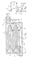
- the channel is essentially enclosed by an approximately cuboid housing 1, which has an inlet 2 for the combustion gases at the top right and an outlet 3 for these gases at the bottom on the left.
- the housing 1 ensures adequate insulation and can be directly connected to the outer wall of the boiler house on the right side. Above all, it is important that the canal as a whole has a horizontal course, i.e. not an extension upwards, but to the side.
- a fan 4 for generating an artificial draft is required for this in the area of the outlet 3, but there is the great advantage that any escaping pollutants are intercepted near the ground and cannot be discharged upwards into the open.
- Each section a - d is assigned a heat exchanger which consists of hollow plates 6 which are horizontal in the parallel position are arranged. On both sides of each heat exchanger, side plates 7 - also held hollow - are arranged vertically. The plates 6, 7 are connected by elbows 8 so that cold water can flow into the heat exchanger at 9 and warm water can drain off at 10.
- the heat exchangers of the different sections a - d are in turn connected to one another in terms of pipes; it is also not absolutely necessary for the partition between two adjacent sections to be formed by the plate 6 of a heat exchanger. Rather, an insulating plate can also be provided as a separation if necessary.
- the grading dimensions x, y and z thus correspond to one another, but opposing gradations are provided if a deflection point 5 is considered.
- the plate 6 located the most outside (at the deflection point 5) delimits the deflection point 5 upwards in the heat exchanger of section a, while the plate 6 lying at the bottom or its end limits the deflection point 5 downwards. This creates a somewhat triangular (equilateral) deflection point 5, the tip of which is directed at the parting plane between adjacent heat exchangers.
- the gradation according to the invention can be achieved most simply by moving a plurality of plates 6 of equal length; for them it is only a matter of their attachment in the sense of the drawing in the offset state, it being advantageous if there is symmetry.
- the separating layer (parting plane) between two superimposed heat exchangers formed by a plate 6 of one of the two heat exchangers.
- the combustion gases are fed from inlet 2 to inlet 11 into the heat exchanger located above via a line 12 which is delimited at the top by the housing 1 and at the bottom by the plate 6 of the heat exchanger of section a located at the top.
- the guidance of the medium to be heated is particularly advantageous if it is carried out in the direction of arrows 13 according to FIG. 2.
- the medium is introduced into the lowermost plate 6 on one side, passed through it, drawn off on the other side and fed to the plate 6 lying above, the plates 7 also being completely dispensed with and the transfer of the water or medium directly from one Plate 6 can be done to another.
- This s-shaped guidance of the medium means that the heated medium can be pulled off at the top in the direction of arrow 10.
Landscapes
- Engineering & Computer Science (AREA)
- Physics & Mathematics (AREA)
- Thermal Sciences (AREA)
- Mechanical Engineering (AREA)
- General Engineering & Computer Science (AREA)
- Heat-Exchange Devices With Radiators And Conduit Assemblies (AREA)
- Instantaneous Water Boilers, Portable Hot-Water Supply Apparatuses, And Control Of Portable Hot-Water Supply Apparatuses (AREA)
- Incineration Of Waste (AREA)
- Chimneys And Flues (AREA)
Applications Claiming Priority (2)
| Application Number | Priority Date | Filing Date | Title |
|---|---|---|---|
| DE4005391 | 1990-02-21 | ||
| DE4005391A DE4005391C2 (de) | 1990-02-21 | 1990-02-21 | Kanal zum Abführen der Verbrennungsgase einer Kesselanlage |
Publications (2)
| Publication Number | Publication Date |
|---|---|
| EP0443440A1 true EP0443440A1 (fr) | 1991-08-28 |
| EP0443440B1 EP0443440B1 (fr) | 1994-04-13 |
Family
ID=6400623
Family Applications (1)
| Application Number | Title | Priority Date | Filing Date |
|---|---|---|---|
| EP91102083A Expired - Lifetime EP0443440B1 (fr) | 1990-02-21 | 1991-02-14 | Canal pour purger les gaz de fumées d'une chaudière |
Country Status (5)
| Country | Link |
|---|---|
| EP (1) | EP0443440B1 (fr) |
| AT (1) | ATE104424T1 (fr) |
| DE (2) | DE4005391C2 (fr) |
| DK (1) | DK0443440T3 (fr) |
| ES (1) | ES2055468T3 (fr) |
Cited By (1)
| Publication number | Priority date | Publication date | Assignee | Title |
|---|---|---|---|---|
| US20140138075A1 (en) * | 2012-11-19 | 2014-05-22 | Industrial Technology Research Institute | Heat exchanger and semiconductor module |
Citations (2)
| Publication number | Priority date | Publication date | Assignee | Title |
|---|---|---|---|---|
| GB276262A (en) * | 1927-03-22 | 1927-08-25 | Babcock & Wilcox Co | Heat transfer devices |
| EP0179161A1 (fr) * | 1983-10-05 | 1986-04-30 | Richard Vetter | Canal pour évacuer des gaz de la combustion d'une chaudière |
Family Cites Families (1)
| Publication number | Priority date | Publication date | Assignee | Title |
|---|---|---|---|---|
| DE3113254A1 (de) * | 1981-04-02 | 1982-10-21 | Richard 3150 Peine Vetter | Vorrichtung zum erwaermen von wasser, insb. warmwasserheizkessel |
-
1990
- 1990-02-21 DE DE4005391A patent/DE4005391C2/de not_active Expired - Fee Related
-
1991
- 1991-02-14 DE DE59101345T patent/DE59101345D1/de not_active Expired - Fee Related
- 1991-02-14 ES ES91102083T patent/ES2055468T3/es not_active Expired - Lifetime
- 1991-02-14 DK DK91102083.2T patent/DK0443440T3/da active
- 1991-02-14 AT AT91102083T patent/ATE104424T1/de not_active IP Right Cessation
- 1991-02-14 EP EP91102083A patent/EP0443440B1/fr not_active Expired - Lifetime
Patent Citations (2)
| Publication number | Priority date | Publication date | Assignee | Title |
|---|---|---|---|---|
| GB276262A (en) * | 1927-03-22 | 1927-08-25 | Babcock & Wilcox Co | Heat transfer devices |
| EP0179161A1 (fr) * | 1983-10-05 | 1986-04-30 | Richard Vetter | Canal pour évacuer des gaz de la combustion d'une chaudière |
Cited By (1)
| Publication number | Priority date | Publication date | Assignee | Title |
|---|---|---|---|---|
| US20140138075A1 (en) * | 2012-11-19 | 2014-05-22 | Industrial Technology Research Institute | Heat exchanger and semiconductor module |
Also Published As
| Publication number | Publication date |
|---|---|
| DK0443440T3 (da) | 1994-07-11 |
| ATE104424T1 (de) | 1994-04-15 |
| EP0443440B1 (fr) | 1994-04-13 |
| DE4005391C2 (de) | 1993-12-09 |
| DE4005391A1 (de) | 1991-08-29 |
| DE59101345D1 (de) | 1994-05-19 |
| ES2055468T3 (es) | 1994-08-16 |
Similar Documents
| Publication | Publication Date | Title |
|---|---|---|
| DE19501547A1 (de) | Modularer Wärmeaustauscher | |
| DE69300289T2 (de) | Vorrichtung zur Reinigung von Abgasen. | |
| AT402551B (de) | Verbrennungsanlage | |
| EP0475261B1 (fr) | Radiateur | |
| DE4005391C2 (de) | Kanal zum Abführen der Verbrennungsgase einer Kesselanlage | |
| DE69102879T2 (de) | Gaskühler zur wärmeübertragung durch konvektion. | |
| DE69809156T2 (de) | Vorrichtung zum Wärmeaustausch für einen Kessel mit zirkulierendem Wirbelbett | |
| EP1126227A1 (fr) | Condenseur de vapeur | |
| DE3232794C2 (de) | Brennkammerboden zu einer Wirbelschichtfeuerung | |
| EP0392150B1 (fr) | Four de boulangerie à circulation de gaz de chauffage | |
| DE2816293A1 (de) | Kuehlturm | |
| DE3103507C2 (de) | Wärmetauscher | |
| DE734477C (de) | Schiffswasserrohrkessel | |
| DE1802286C3 (de) | Röhren-Wärmetauscher für die Kühlung von Rauchgasen aus Feuerungsanlagen | |
| DE3427957A1 (de) | Kondensatheizkessel | |
| DE2906534C2 (de) | Mehrgängiger, Korrosionsbeständiger Luftvorwärmer | |
| DE8814405U1 (de) | Vorrichtung zum Entsticken von Kraftwerksabgasen | |
| DE2360785C3 (de) | Plattenwärmetauscher für Fluide | |
| DE1758267C (de) | Kuhlkamin | |
| DE2622298C3 (de) | Dampferzeuger für eine Wärmekraftanlage | |
| AT270716B (de) | Verfahren zur Kühlung von heißen Abgasen und Kühlkamin zur Durchführung des Verfahrens | |
| EP0591563B1 (fr) | Chaudière | |
| DE1758267B1 (de) | Kuehlkamin | |
| DE3624708A1 (de) | Heizkessel | |
| DE6607833U (de) | Hochdruckbeheizter kessel mit zwischen zwei wassermaenteln angeordneten mehrfachen rauchfuehrungen. |
Legal Events
| Date | Code | Title | Description |
|---|---|---|---|
| PUAI | Public reference made under article 153(3) epc to a published international application that has entered the european phase |
Free format text: ORIGINAL CODE: 0009012 |
|
| AK | Designated contracting states |
Kind code of ref document: A1 Designated state(s): AT BE CH DE DK ES FR GB GR IT LI LU NL SE |
|
| 17P | Request for examination filed |
Effective date: 19910709 |
|
| 17Q | First examination report despatched |
Effective date: 19920713 |
|
| GRAA | (expected) grant |
Free format text: ORIGINAL CODE: 0009210 |
|
| AK | Designated contracting states |
Kind code of ref document: B1 Designated state(s): AT BE CH DE DK ES FR GB GR IT LI LU NL SE |
|
| PG25 | Lapsed in a contracting state [announced via postgrant information from national office to epo] |
Ref country code: SE Free format text: THE PATENT HAS BEEN ANNULLED BY A DECISION OF A NATIONAL AUTHORITY Effective date: 19940413 Ref country code: GR Free format text: LAPSE BECAUSE OF FAILURE TO SUBMIT A TRANSLATION OF THE DESCRIPTION OR TO PAY THE FEE WITHIN THE PRESCRIBED TIME-LIMIT Effective date: 19940413 |
|
| REF | Corresponds to: |
Ref document number: 104424 Country of ref document: AT Date of ref document: 19940415 Kind code of ref document: T |
|
| REF | Corresponds to: |
Ref document number: 59101345 Country of ref document: DE Date of ref document: 19940519 |
|
| ITF | It: translation for a ep patent filed | ||
| ET | Fr: translation filed | ||
| REG | Reference to a national code |
Ref country code: DK Ref legal event code: T3 |
|
| REG | Reference to a national code |
Ref country code: ES Ref legal event code: FG2A Ref document number: 2055468 Country of ref document: ES Kind code of ref document: T3 |
|
| GBT | Gb: translation of ep patent filed (gb section 77(6)(a)/1977) |
Effective date: 19940715 |
|
| PLBE | No opposition filed within time limit |
Free format text: ORIGINAL CODE: 0009261 |
|
| STAA | Information on the status of an ep patent application or granted ep patent |
Free format text: STATUS: NO OPPOSITION FILED WITHIN TIME LIMIT |
|
| PG25 | Lapsed in a contracting state [announced via postgrant information from national office to epo] |
Ref country code: LU Free format text: LAPSE BECAUSE OF NON-PAYMENT OF DUE FEES Effective date: 19950228 |
|
| 26N | No opposition filed | ||
| PGFP | Annual fee paid to national office [announced via postgrant information from national office to epo] |
Ref country code: DE Payment date: 20010426 Year of fee payment: 11 |
|
| REG | Reference to a national code |
Ref country code: GB Ref legal event code: IF02 |
|
| PGFP | Annual fee paid to national office [announced via postgrant information from national office to epo] |
Ref country code: GB Payment date: 20020208 Year of fee payment: 12 |
|
| PGFP | Annual fee paid to national office [announced via postgrant information from national office to epo] |
Ref country code: ES Payment date: 20020221 Year of fee payment: 12 |
|
| PGFP | Annual fee paid to national office [announced via postgrant information from national office to epo] |
Ref country code: DK Payment date: 20020225 Year of fee payment: 12 |
|
| PGFP | Annual fee paid to national office [announced via postgrant information from national office to epo] |
Ref country code: FR Payment date: 20020226 Year of fee payment: 12 |
|
| PGFP | Annual fee paid to national office [announced via postgrant information from national office to epo] |
Ref country code: AT Payment date: 20020227 Year of fee payment: 12 |
|
| PGFP | Annual fee paid to national office [announced via postgrant information from national office to epo] |
Ref country code: NL Payment date: 20020228 Year of fee payment: 12 |
|
| PGFP | Annual fee paid to national office [announced via postgrant information from national office to epo] |
Ref country code: BE Payment date: 20020312 Year of fee payment: 12 |
|
| PGFP | Annual fee paid to national office [announced via postgrant information from national office to epo] |
Ref country code: CH Payment date: 20020326 Year of fee payment: 12 |
|
| PG25 | Lapsed in a contracting state [announced via postgrant information from national office to epo] |
Ref country code: DE Free format text: LAPSE BECAUSE OF NON-PAYMENT OF DUE FEES Effective date: 20020903 |
|
| PG25 | Lapsed in a contracting state [announced via postgrant information from national office to epo] |
Ref country code: GB Free format text: LAPSE BECAUSE OF NON-PAYMENT OF DUE FEES Effective date: 20030214 Ref country code: AT Free format text: LAPSE BECAUSE OF NON-PAYMENT OF DUE FEES Effective date: 20030214 |
|
| PG25 | Lapsed in a contracting state [announced via postgrant information from national office to epo] |
Ref country code: ES Free format text: LAPSE BECAUSE OF NON-PAYMENT OF DUE FEES Effective date: 20030215 |
|
| PG25 | Lapsed in a contracting state [announced via postgrant information from national office to epo] |
Ref country code: LI Free format text: LAPSE BECAUSE OF NON-PAYMENT OF DUE FEES Effective date: 20030228 Ref country code: DK Free format text: LAPSE BECAUSE OF NON-PAYMENT OF DUE FEES Effective date: 20030228 Ref country code: CH Free format text: LAPSE BECAUSE OF NON-PAYMENT OF DUE FEES Effective date: 20030228 Ref country code: BE Free format text: LAPSE BECAUSE OF NON-PAYMENT OF DUE FEES Effective date: 20030228 |
|
| PG25 | Lapsed in a contracting state [announced via postgrant information from national office to epo] |
Ref country code: NL Free format text: LAPSE BECAUSE OF NON-PAYMENT OF DUE FEES Effective date: 20030901 |
|
| REG | Reference to a national code |
Ref country code: DK Ref legal event code: EBP |
|
| GBPC | Gb: european patent ceased through non-payment of renewal fee | ||
| REG | Reference to a national code |
Ref country code: CH Ref legal event code: PL |
|
| PG25 | Lapsed in a contracting state [announced via postgrant information from national office to epo] |
Ref country code: FR Free format text: LAPSE BECAUSE OF NON-PAYMENT OF DUE FEES Effective date: 20031031 |
|
| NLV4 | Nl: lapsed or anulled due to non-payment of the annual fee |
Effective date: 20030901 |
|
| REG | Reference to a national code |
Ref country code: FR Ref legal event code: ST |
|
| REG | Reference to a national code |
Ref country code: ES Ref legal event code: FD2A Effective date: 20030215 |
|
| PG25 | Lapsed in a contracting state [announced via postgrant information from national office to epo] |
Ref country code: IT Free format text: LAPSE BECAUSE OF NON-PAYMENT OF DUE FEES;WARNING: LAPSES OF ITALIAN PATENTS WITH EFFECTIVE DATE BEFORE 2007 MAY HAVE OCCURRED AT ANY TIME BEFORE 2007. THE CORRECT EFFECTIVE DATE MAY BE DIFFERENT FROM THE ONE RECORDED. Effective date: 20050214 |