EP0443418B1 - Textile machine - Google Patents
Textile machine Download PDFInfo
- Publication number
- EP0443418B1 EP0443418B1 EP91101966A EP91101966A EP0443418B1 EP 0443418 B1 EP0443418 B1 EP 0443418B1 EP 91101966 A EP91101966 A EP 91101966A EP 91101966 A EP91101966 A EP 91101966A EP 0443418 B1 EP0443418 B1 EP 0443418B1
- Authority
- EP
- European Patent Office
- Prior art keywords
- textile
- control unit
- belt
- drive
- machine according
- Prior art date
- Legal status (The legal status is an assumption and is not a legal conclusion. Google has not performed a legal analysis and makes no representation as to the accuracy of the status listed.)
- Expired - Lifetime
Links
Images

Classifications
-
- D—TEXTILES; PAPER
- D01—NATURAL OR MAN-MADE THREADS OR FIBRES; SPINNING
- D01H—SPINNING OR TWISTING
- D01H9/00—Arrangements for replacing or removing bobbins, cores, receptacles, or completed packages at paying-out or take-up stations ; Combination of spinning-winding machine
- D01H9/18—Arrangements for replacing or removing bobbins, cores, receptacles, or completed packages at paying-out or take-up stations ; Combination of spinning-winding machine for supplying bobbins, cores, receptacles, or completed packages to, or transporting from, paying-out or take-up stations ; Arrangements to prevent unwinding of roving from roving bobbins
-
- B—PERFORMING OPERATIONS; TRANSPORTING
- B65—CONVEYING; PACKING; STORING; HANDLING THIN OR FILAMENTARY MATERIAL
- B65H—HANDLING THIN OR FILAMENTARY MATERIAL, e.g. SHEETS, WEBS, CABLES
- B65H67/00—Replacing or removing cores, receptacles, or completed packages at paying-out, winding, or depositing stations
- B65H67/04—Arrangements for removing completed take-up packages and or replacing by cores, formers, or empty receptacles at winding or depositing stations; Transferring material between adjacent full and empty take-up elements
- B65H67/0428—Arrangements for removing completed take-up packages and or replacing by cores, formers, or empty receptacles at winding or depositing stations; Transferring material between adjacent full and empty take-up elements for cans, boxes and other receptacles
-
- D—TEXTILES; PAPER
- D01—NATURAL OR MAN-MADE THREADS OR FIBRES; SPINNING
- D01G—PRELIMINARY TREATMENT OF FIBRES, e.g. FOR SPINNING
- D01G21/00—Combinations of machines, apparatus, or processes, e.g. for continuous processing
-
- D—TEXTILES; PAPER
- D01—NATURAL OR MAN-MADE THREADS OR FIBRES; SPINNING
- D01H—SPINNING OR TWISTING
- D01H5/00—Drafting machines or arrangements ; Threading of roving into drafting machine
-
- B—PERFORMING OPERATIONS; TRANSPORTING
- B65—CONVEYING; PACKING; STORING; HANDLING THIN OR FILAMENTARY MATERIAL
- B65H—HANDLING THIN OR FILAMENTARY MATERIAL, e.g. SHEETS, WEBS, CABLES
- B65H2701/00—Handled material; Storage means
- B65H2701/30—Handled filamentary material
- B65H2701/31—Textiles threads or artificial strands of filaments
Definitions
- the invention relates to a textile machine according to the preamble of claim 1.
- the feed and discharge unit seen in terms of control and drive, are fully integrated into the drive and control unit of the textile processing machine.
- Today's drive technology especially the single drive via electric motors, enables a very finely tuned and controllable drive, whereby the communication of individual drive groups can also be carried out easily and with almost no losses.
- a textile processing machine which delivers the textile material, in this case a sliver, to a can filling station provided with its own drive. Differences in the delivery speed of the sliver between the textile processing machine and the subsequent can filling station are detected by a sensor device and the drive of the can filling station is regulated according to the values determined in the process.
- the central filling computer and the textile processing machine are controlled by a central control computer.
- this system is not readily transferable to the supply of textile material by means of a supply device to the textile processing machine.
- a supply device to the textile processing machine.
- a feed unit can also be started independently of the subsequent textile processing machine. This is particularly necessary when a new batch of textile material has to be set up and positioned accordingly for transfer to the textile processing machine. This is particularly the case if a part of the discarded textile material is kept on hold as a reserve material.
- FR-A 25 87 042 proposes that the position of "Flexafeed" flaps on a card be recorded by a central control unit in order to determine the new routes and destinations of a transport trolley depending on the flap position.
- the dispensing unit on the card has no control of its own, so that a material jam on the textile machine cannot be avoided.
- DE-OS 32 37 864 describes the closest prior art to a textile machine for processing textile material with a control and drive unit and a feed device for feeding textile material which is removed from the textile material store associated with the feed device.
- the textile processing machine is also assigned a tape storage device, which delivers the textile material to the corresponding storage device.
- DE-OS 32 37 864 also shows that the feed device is equipped with an independent control and drive unit. This also applies to the tape storage.
- This solution is disadvantageous, as shown below. If a transport system takes over filled cans from the textile machine on the conveyor, the operation of the feed device continues without a can change being taken into account. This can lead to belt jams or undesired belt warping in the textile machine. This malfunction caused by the feeding device must be avoided.
- This solution also presents difficulties when connecting an end of the tape that is running out to a new tape to be introduced. There is a risk of incorrect positioning of the tape end, since the feed device runs at a lower speed when the reserve tape is switched on in the start-up phase and the processing speed of the dispensing device cannot be controlled to the state of the reserve tape feed.
- the invention is based on the object of designing the individual drive and control concepts of both a feed device and a belt storage of a textile-processing machine in such a way that interaction with transport systems for sliver material is possible from the point of view of automation.
- Automation can be understood on the one hand to mean the automatic tracking of textile material without stopping the textile processing machine and on the other hand the connection to an automatic transport system for the textile material.
- the solution according to the invention has the advantage that the feed speed can be controlled in synchronization with the processing speed.
- Another advantage results from the possibility that a failure of a thread band can be reported to the control computer of the transport system in the feed device. It is thus achieved that a connection of an outgoing sliver to the start of a switched-on reserve sliver is possible by exact sliver end positioning.
- each conveyor belt of a feed device has its own drive motor which is guided by the control unit of the feed device. This enables a targeted and separate reserve band connection.
- the conveyor belts for the work belt and reserve belt are preferably combined in pairs.
- the conveyor belts each have a withdrawal device for withdrawing the sliver from a can.
- an attenuator was connected in the connection path between the corresponding control and regulating devices.
- stepper motors results in an exact determination of the position during the entire transport process of the sliver, e.g. a beginning of a sliver, seen in the direction of transport.
- electronically commutated brushless motors e.g. DC motors have the advantage that the drive of the conveyor belt can also work in the overload range at short notice and without problems.
- the teaching claimed by the invention provides a good possibility of regulating the entire system through direct control.
- the independent drive also shortens the drive distances and thus also reduces losses.
- the drives can be designed specifically for the individual purpose.
- the proposed control, regulation and drive-related separation enables better allocation and communication to an assigned automatic transport system for the textile material.
- Figure 1 shows a textile processing machine, e.g. a route 1, which is provided with a drafting system, not shown.
- a feed table 2 is provided as the feed unit, and a belt storage 3 is provided as the delivery unit.
- Cans A, R for removing fiber slivers are set up along the feed table 2.
- the space which the cans A, R occupy is generally also referred to as a can rack 4.
- empty spaces can also be provided for receiving cans by the transport unit. This can improve the logistics of the transport system and thus its effectiveness.
- the directional arrow P shows the feed and the direction of passage of the textile material before it reaches the tape storage 3.
- a transport system T 1 with a driverless transport vehicle 5 guided over a guideline 6 is assigned to the feed table 2 or the can frame 4.
- the transport vehicle 5 is controlled by a control computer 7. This means that the transport vehicle receives the drive command or the drive order from the control computer 7 via a connection 8.
- the connection 8 can be wireless, via a connection cable or via a communication station.
- the drive 9 of the feed table 2 and the sensor system 10 is shown schematically.
- the drive 9 is connected to a control unit 13 via a path 11 and the sensor system 10 via a path 12.
- the control unit 13 communicates via the line 14 with the control computer 7 of the transport system T 1 .
- the paths 15 and 16 form a communication option between the control unit 17 of the drive unit 18 of the route 1.
- the schematically illustrated sensor system 19 of the route 1 is connected to the control unit 17 via the path 21.
- the two connections 22 and 23 enable communication between the control unit 17 and the control unit 24 of the tape storage unit 3.
- the control unit 24 is connected via the paths 25 to a schematically illustrated drive 26 and via the path 27 to a sensor system 28 of the tape storage unit 3.
- the control computer 30 communicates via a connection 32 with a transport vehicle 31, which is guided via a guide 33.
- a can F 2 is in the filling station, while an empty can F 1 is ready for tracking.
- F3 denotes a filled can, which was ejected from the tape storage 3 after the filling process and is ready for reception by the transport vehicle 31.
- the guideline 33 is provided with a reversing loop 34.
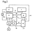
- FIG. 2 shows a more detailed breakdown of the drive and control mechanism for the feed table 2.
- a motor electronics 35 which acts on a motor 36.
- a connection 37 into which an attenuator 38 is switched on.
- the motor electronics 35 or the motor 36 receives a command signal via this connection 37 in order to ensure the synchronization with respect to the feed speed of the textile material and the processing speed.
- the motor electronics are controlled via the path 11 by the control unit 13.
- the lines 40 and 41 represent a connection between the control unit 13 and a display and operating unit 39.
- a voltage supply unit 42 supplies the display and operating unit via line 44, the control unit 13 via line 43, and the sensor system via line 47 10 and via line 46 the motor electronics 35 with current.
- the power supply 42 is switched on by the control unit 17 of the line 1 via the line 45. In the specific case, this means that the voltage supply 42 only becomes effective when the control unit 17 or. route 1 is switched on.
- the connection 48 between the sensor system 10 and the motor electronics 35 makes it possible to intervene directly in the motor electronics for motor control. In certain cases, this allows the reaction time to change the engine speed to be shortened, since the computer unit of the control unit 13 is bypassed.
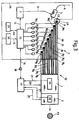
- FIG. 3 An exemplary embodiment is shown in FIG. 3, the feed table 2 being composed of a total of eight individual conveyor belts B 1 to B 8 .
- Each conveyor belt B 1 to B 8 is equipped with a separate drive motor 36 1 to 36 8 .
- the drive motors 36 1 to 36 8 are each located above a draw-off point above a can, only one can A being shown because of the better overview.
- the other seven cans are assigned accordingly.
- swiveling pressure rollers 49 are assigned to each of the withdrawal points. During operation, these rollers 49 move in the direction of the respective conveyor belt B 1 to B 8 and thereby enable the respective sliver to be pulled off by the clamping between the conveyor belt and the pressure roller 49.
- sliver 50 at the transfer point 52 submitted the route 1.
- the slivers 50 released in the process are combined at this transfer point 52 (not shown) to form a sliver fleece before it is fed to the drafting system of the section 1.
- the other slivers also called reserve belts 51 in this operating state, are in the starting position below a sensor row S and are switched on in accordance with the failure of a sliver 50, i.e. one of the conveyor belts B 1 to B 8 must be started up and switched on via the respective motor 36 .
- the monitoring of the slivers or the sliver break can also take place directly in the area of the withdrawal points.
- the transport vehicle 5 with the guideline 6 is only indicated schematically here.
- the line 1 and the tape storage 3 are connected to form a unit, which are controlled by a control unit 17.
- the sensor system 19 of the route 1 and the sensor system 28 of the tape storage 3 are connected to the control unit 17 via the paths 21 and 27.
- the special indication of the respective drive unit has been omitted.
- a control signal is transmitted from route 1 via control unit 17 and control unit 13 to the individual electronic control units 35 1 to 35 8 of motors 36 1 to 36 8 .
- An attenuator 38 is installed in the path 16 provided for this purpose to damp short-wave signals.
- Each can parking space is assigned a can sensor 53, which is connected to the control unit 13 via a line 54 and the sensor system 10 and the path 12. For reasons of clarity, only one sensor 53 was shown in the example in FIG. 3.
- the sensors 53 can also on the one hand to check whether a jug is present, or on the other hand to check the contents of the jug. These signals received by the sensors 53 are relevant for the provision of cans and for the preparation of the tracking of a reserve belt.
- the further insertion of the fiber slivers 50 into the subsequent drafting device or the fiber sliver that subsequently emerges from the drafting device into the sliver storage can be done manually or automatically.
- the engine speed of the motors 36 1 to 36 8 is adjusted according to the control dynamics of the drafting system of the route 1 via the path 16.
- a sliver breaks down as a result of a sliver break or an empty can, after notification via the sensor system 10, the corresponding conveyor belt B is switched on with the reserve belt 51, in such a way that the end of the sliver running out coincides with the start of the connected reserve belt 51 covered. This requires an exact sensor system and an exact start of the corresponding conveyor belt.
- the report of a failed sliver or an empty can is transmitted by the control unit 13 via the line 14 to the control computer 7 of the transport system T 1 . With this transmission, the position of the stand of the empty can is also transmitted, whereby the host computer can transmit a clear driving order to the transport vehicle 5 for picking up and replacing the corresponding can with a new filled can.
- a further transport system T 2 was not shown in FIG. 3. However, the structure could be similar to that shown in the example in FIG. 1.
- the example according to FIG. 1 differs essentially from that in FIG. 3 in that the section 1 and the tape storage 3 each have their own control and drive unit, which communicate with one another via the respective control unit 17 or 24. Otherwise, the example according to FIG. 1 differs insignificantly from the example according to FIG. 3.
- FIG. 3 only the feed table 2 was shown in a special embodiment and with a finer structure.
- the additional transport system T 2 in the example of FIG. 1 has the task of conveying empty cans F 1 to the band deposit and to transport away the full cans F3 ejected in this band deposit 3.
- the control unit 30 of this transport system T 2 is connected to the control unit 24 of the tape storage 3 via the path 29.
Landscapes
- Engineering & Computer Science (AREA)
- Textile Engineering (AREA)
- Mechanical Engineering (AREA)
- Spinning Or Twisting Of Yarns (AREA)
Description
Die Erfindung bezieht sich auf eine Textilmaschine nach dem Oberbegriff des Anspruches 1.The invention relates to a textile machine according to the preamble of
In einer Spinnerei werden je nach Prozesstufe unterschiedliche textilverarbeitende Maschinen eingesetzt. Als gemeinsames Merkmal haben diese unterschiedlichen Maschinentypen eine Zuführungs- und Abgabeeinheit für das zu verarbeitende Textilmaterial.Depending on the process level, different textile processing machines are used in a spinning mill. As a common feature, these different machine types have a feed and delivery unit for the textile material to be processed.
Im wesentlichen sind bei diesen Maschinen die Zuführ- und Abgabeeinheit, steuerungs- und antriebsmässig gesehen, in die Antriebs- und Steuereinheit der textilverarbeitenden Maschine voll integriert.Essentially, in these machines, the feed and discharge unit, seen in terms of control and drive, are fully integrated into the drive and control unit of the textile processing machine.
Die heutige Antriebstechnik, insbesondere der Einzelantrieb über Elektromotoren, ermöglicht einen sehr fein abgestimmten und regelbaren Antrieb, wobei auch die Kommunikation einzelner Antriebsgruppen problemlos und fast ohne Verluste durchführbar ist.Today's drive technology, especially the single drive via electric motors, enables a very finely tuned and controllable drive, whereby the communication of individual drive groups can also be carried out easily and with almost no losses.
Aus der DE-OS 22 30 069 ist eine textilverarbeitende Maschine bekannt, welche das Textilmaterial, in diesem Fall ein Faserband, an eine mit einem eigenen Antrieb versehene Kannenfüllstation abgibt. Dabei werden Unterschiede der Liefergeschwindigkeit des Faserbandes zwischen der textilverarbeitenden Maschine und der nachfolgenden Kannenfüllstation über eine Sensoreinrichtung erfasst und der Antrieb der Kannenfüllstation entsprechend den dabei ermittelten Werten geregelt. Die Steuerung der Kannenfüllstation sowie der textilverarbeitenden Maschine wird von einem zentralen Leitrechner vorgenommen.From DE-OS 22 30 069 a textile processing machine is known which delivers the textile material, in this case a sliver, to a can filling station provided with its own drive. Differences in the delivery speed of the sliver between the textile processing machine and the subsequent can filling station are detected by a sensor device and the drive of the can filling station is regulated according to the values determined in the process. The central filling computer and the textile processing machine are controlled by a central control computer.
Dieses System ist jedoch nicht ohne weiteres auf die Zuführung von Textilmaterial mittels einer Zuführeinrichtung zur textilverarbeitenden Maschine übertragbar. Im Hinblick auf eine automatisierte Spinnerei sind bei der Zuführeinrichtung noch weitere Forderungen zu erfüllen, welche der zuvor geschilderte Stand der Technik der Abgabeeinheit nicht beinhaltet. So wird z.B. gefordert, daß eine Zuführeinheit auch unabhängig von der nachfolgenden textilverarbeitenden Maschine ausgestartet werden kann. Dies ist insbesondere dann notwendig, wenn eine neue Textilmaterial-Charge angesetzt und entsprechend zur Über-/Abgabe an die textilverarbeitende Maschine positioniert werden muß. Dieser Fall tritt insbesondere ein, wenn ein Teil des aufgegebenen Textilmaterials als Reservematerial in einer Wartestellung gehalten wird.However, this system is not readily transferable to the supply of textile material by means of a supply device to the textile processing machine. With regard to an automated spinning mill are at the feeder to meet further requirements which the previously described state of the art of the delivery unit does not include. For example, it is required that a feed unit can also be started independently of the subsequent textile processing machine. This is particularly necessary when a new batch of textile material has to be set up and positioned accordingly for transfer to the textile processing machine. This is particularly the case if a part of the discarded textile material is kept on hold as a reserve material.
Aus der weiterhin bekannten DE-AS 22 30 644 ist ein Zuführtisch zu einer textilverarbeitenden Maschine zu entnehmen, wobei die Steuerung, bzw. Zuschaltung von Abzugseinrichtungen für Faserbänder über elektromagnetische Kupplungen, vorgenommen wird. Dabei sind jeweils zwei Druckrollenpaare mit Kontroll- und Steuerelementen versehen, welche beim Ausfall des Arbeitsbandes das entsprechende in einer Wartestellung befindliche Reserveband zuschalten. Der Antrieb der Förderwalzen sowie des Transportbandes zum Zuführen von Faserbänder ist mit dem Antrieb steuerungsmäßig und mechanisch verbunden.From the still known DE-AS 22 30 644, a feed table to a textile processing machine can be seen, the control or connection of take-off devices for fiber slivers via electromagnetic couplings being carried out. Two pairs of pressure rollers are each provided with control and control elements, which switch on the corresponding reserve belt, which is in a waiting position, if the working belt fails. The drive of the conveyor rollers and the conveyor belt for feeding fiber slivers is mechanically and mechanically connected to the drive.
Die FR-A 25 87 042 schlägt vor, die Stellung von "Flexafeed"-Klappen an einer Karde durch eine zentrale Steuereinheit zu erfassen, um in Abhängigkeit der Klappenstellung die neuen Wege und Ziele eines Transportwagens zu bestimmen. Die Abgabeeinheit an der Karde hat keine eigene Steuerung, so daß ein Materialstau an der Textilmaschine nicht vermeidbar ist.FR-A 25 87 042 proposes that the position of "Flexafeed" flaps on a card be recorded by a central control unit in order to determine the new routes and destinations of a transport trolley depending on the flap position. The dispensing unit on the card has no control of its own, so that a material jam on the textile machine cannot be avoided.
Die DE-OS 32 37 864 beschreibt als den am nächsten liegenden Stand der Technik eine Textilmaschine zur Verarbeitung von Textilmaterial mit einer Steuer- und Antriebseinheit sowie einer Zuführeinrichtung zur Zuführung von Textilmaterial, welches aus der Zuführeinrichtung zugeordneten Textilmaterial-Speichern entnommen wird. Der textilverarbeitenden Maschine ist weiterhin eine Bandablage, welche das abgegebene Textilmaterial an entsprechende Aufnahmespeicher abgibt, zugeordnet. Die DE-OS 32 37 864 zeigt weiterhin, daß die Zuführeinrichtung mit einer eigenständigen Steuer- und Antriebseinheit ausgerüstet ist. Das betrifft auch die Bandablage. Diese Lösung ist nachteilig, wie sich nachfolgend zeigt. Übernimmt ein Transportsystem von der Textilmaschine an der Bandablage gefüllte Kannen, läuft der Betrieb der Zuführeinrichtung weiter, ohne daß ein Kannenwechsel Berücksichtigung findet. Dies kann zum Bandstau bzw. unerwünschtem Bandverzug in der Textilmaschine führen. Diese durch die Zuführeinrichtung verursachte Störung ist zu vermeiden. Schwierigkeiten bereitet diese Lösung auch bei der Verbindung eines auslaufenden Bandendes mit einem neu einzuführenden Reserveband. Es besteht die Gefahr einer fehlerhaften Positionierung des Bandendes, da die Zuführeinrichtung bei Reservebandzuschaltung in der Anlaufphase mit geringerer Geschwindigkeit läuft und die Verarbeitungsgeschwindigkeit der Abgabeeinrichtung nicht auf den Zustand der Reservebandzuführung steuerbar ist.DE-OS 32 37 864 describes the closest prior art to a textile machine for processing textile material with a control and drive unit and a feed device for feeding textile material which is removed from the textile material store associated with the feed device. The textile processing machine is also assigned a tape storage device, which delivers the textile material to the corresponding storage device. DE-OS 32 37 864 also shows that the feed device is equipped with an independent control and drive unit. This also applies to the tape storage. This solution is disadvantageous, as shown below. If a transport system takes over filled cans from the textile machine on the conveyor, the operation of the feed device continues without a can change being taken into account. This can lead to belt jams or undesired belt warping in the textile machine. This malfunction caused by the feeding device must be avoided. This solution also presents difficulties when connecting an end of the tape that is running out to a new tape to be introduced. There is a risk of incorrect positioning of the tape end, since the feed device runs at a lower speed when the reserve tape is switched on in the start-up phase and the processing speed of the dispensing device cannot be controlled to the state of the reserve tape feed.
Der Erfindung liegt nunmehr die Aufgabe zugrunde, die einzelnen Antriebs- und Steuerungskonzepte sowohl einer Zuführeinrichtung als auch einer Bandablage einer textilverarbeitenden Maschine so auszubilden, daß ein Zusammenwirken mit Transportsystemen für Faserbandmaterial unter dem Gesichtspunkt der Automatisation möglich wird. Unter Automatisation kann dabei einerseits die automatische Nachführung von Textilmaterial, ohne Stop der textilverarbeitenden Maschine und andererseits der Anschluß an ein automatisches Transportsystem für das Textilmaterial verstanden werden.The invention is based on the object of designing the individual drive and control concepts of both a feed device and a belt storage of a textile-processing machine in such a way that interaction with transport systems for sliver material is possible from the point of view of automation. Automation can be understood on the one hand to mean the automatic tracking of textile material without stopping the textile processing machine and on the other hand the connection to an automatic transport system for the textile material.
Diese Aufgabe wird bei einer gattungsgemäßen Textilmaschine durch die kennzeichnenden Merkmale des Anspruchs 1 gelöst.This object is achieved in a generic textile machine by the characterizing features of
Die erfindungsgemäße Lösung bringt den Vorteil, daß die Zuführgeschwindigkeit in Gleichlauf mit der Verarbeitungsgeschwindigkeit gesteuert werden kann.The solution according to the invention has the advantage that the feed speed can be controlled in synchronization with the processing speed.
Ein weiterer Vorteil ergibt sich aus der Möglichkeit, daß ein Ausfall eines Fadenbandes bei der Zuführeinrichtung an den Leitrechner des Transportsystems gemeldet werden kann. Es wird somit erreicht, daß eine Verbindung eines auslaufenden Faserbandes mit dem Anfang eines zugeschalteten Reservebandes durch exakte Bandendenpositionierung möglich wird.Another advantage results from the possibility that a failure of a thread band can be reported to the control computer of the transport system in the feed device. It is thus achieved that a connection of an outgoing sliver to the start of a switched-on reserve sliver is possible by exact sliver end positioning.
Da diese Zuführeinrichtung aus mehreren, umlaufenden Förderbändern besteht, kann es bei der erfindungsgemäßen Verbindung vorteilhaft sein, wenn jedes Förderband einer Zuführeinrichtung einen eigenen Antriebsmotor hat, der von der Steuereinheit der Zuführeinrichtung geführt wird. Das ermöglicht eine gezielte und separate Reservebandzuschaltung. In diesem Sinne sind die Transportbänder für Arbeitsband und Reserveband vorzugsweise paarweise zusammengefaßt. Die Transportbänder besitzen je eine Abzugseinrichtung zum Abzug des Faserbandes aus einer Kanne.Since this feed device consists of several revolving conveyor belts, it can be advantageous in the connection according to the invention if each conveyor belt of a feed device has its own drive motor which is guided by the control unit of the feed device. This enables a targeted and separate reserve band connection. In this sense, the conveyor belts for the work belt and reserve belt are preferably combined in pairs. The conveyor belts each have a withdrawal device for withdrawing the sliver from a can.
Um kurzwellige Signale zwischen Zuführeinrichtung und textilverarbeitender Maschine zu filtern, wurde ein Dämpfungsglied in den Verbindungspfad zwischen den entsprechenden Steuer- und Regeleinrichtungen geschaltet.In order to filter short-wave signals between the feed device and the textile processing machine, an attenuator was connected in the connection path between the corresponding control and regulating devices.
Werden der textilverarbeitenden Maschine, z.B. einer Strecke, Faserbänder vorgelegt, so ergibt die Förderung der einzelnen Faserbänder auf mehreren umlaufenden über dem Boden abgestützten Förderbändern eine Möglichkeit, die Zufuhr der einzelnen Faserbänder exakt zu steuern. Vorteilhafterweise wird dabei jedem Förderband ein separater Antriebsmotor zugeordnet.Are the textile processing machine, e.g. a route, slivers submitted, so the promotion of the individual slivers on several revolving conveyor belts supported above the ground gives a way to control the supply of the individual slivers exactly. A separate drive motor is advantageously assigned to each conveyor belt.
Die Verwendung von elektrischen Schrittmotoren ergibt hierbei während des gesamten Transportvorganges des Faserbandes eine exakte Bestimmung der Lage, z.B. eines Anfangs eines nachgeführten Faserbandes, in Transportrichtung gesehen. Die weiterhin vorgeschlagene Verwendung von elektronisch kommutierten bürstenlosen Motoren, z.B. Gleichstrommotoren, ergibt den Vorteil, daß der Antrieb des Transportbandes auch kurzfristig und ohne Probleme im Überlastbereich arbeiten kann.The use of electric stepper motors results in an exact determination of the position during the entire transport process of the sliver, e.g. a beginning of a sliver, seen in the direction of transport. The further proposed use of electronically commutated brushless motors, e.g. DC motors have the advantage that the drive of the conveyor belt can also work in the overload range at short notice and without problems.
Um ein problemloses Zusammenwirken der textilverarbeitenden Maschine in Bezug auf die Liefergeschwindigkeit des zugeführten Textilmaterials zu gewährleisten, wird vorgeschlagen, einen Verbindungspfad zwischen der Steuer- und Regeleinheit der textilverarbeitenden Maschine und der Steuerelektronik der Antriebsmotoren zur Übermittlung von Führungssignalen vorzusehen.In order to ensure a problem-free interaction of the textile processing machine with regard to the delivery speed of the textile material supplied, it is proposed to provide a connection path between the control and regulating unit of the textile processing machine and the control electronics of the drive motors for transmitting guide signals.
Damit es zwischen der Zuführeinrichtung und der Bandablage keinen Fehlverzug des Textilmateriales gibt, ist ein Gleichlauf dieser beiden Einrichtungen unbedingt erforderlich.In order that there is no misalignment of the textile material between the feed device and the belt deposit, a synchronism of these two devices is absolutely necessary.
Um jedoch ein Aufschaukeln des gesamten Systems bei auftretenden kurzwelligen Störungen zu vermeiden, wird vorgeschlagen, in dem Verbindungspfad ein Dämpfungsglied zur Ausfilterung dieser Signale vorzusehen.However, in order to prevent the entire system from rocking when short-wave interference occurs, it is proposed to provide an attenuator in the connection path for filtering out these signals.
Die mit der Erfindung in Anspruch genommene Lehre ergibt eine gute Regelmöglichkeit des gesamten Systems durch die direkte Ansteuerung. Außerdem werden durch den selbständigen Antrieb die Antriebswege verkürzt und somit auch die Verluste kleiner. Außerdem können die Antriebe aufgrund des Baukastensystems ganz speziell für den einzelnen Verwendungszweck ausgelegt werden. Die vorgeschlagene steuerungs- und regelungstechnische sowie antriebsmäßige Trennung ermöglicht eine bessere Zuordnung und Kommunikation zu einem zugeordneten automatischen Transportsystem für das Textilmaterial.The teaching claimed by the invention provides a good possibility of regulating the entire system through direct control. The independent drive also shortens the drive distances and thus also reduces losses. In addition, due to the modular system, the drives can be designed specifically for the individual purpose. The proposed control, regulation and drive-related separation enables better allocation and communication to an assigned automatic transport system for the textile material.
Weitere Vorteile sind anhand nachfolgender Ausführungsbeispiele und deren Beschreibung zu entnehmen.Further advantages can be found on the basis of the following exemplary embodiments and their description.
Es zeigen:
Figur 1- eine schematische Draufsicht auf eine textilverarbeitende Maschine mit einer Zu- und Abführeinheit mit einem Transportsystem
Figur 2- ein schematisches Blockschaltbild für den Antrieb und die Steuerung der Zuführeinheit nach
Figur 1 Figur 3- eine schematische Draufsicht auf eine Ausführungsform der Zuführeinheit mit einzelnen Transportbändern
- Figure 1
- is a schematic plan view of a textile processing machine with a feed and discharge unit with a transport system
- Figure 2
- 2 shows a schematic block diagram for the drive and the control of the feed unit according to FIG. 1
- Figure 3
- is a schematic plan view of an embodiment of the feed unit with individual conveyor belts
Figur 1 zeigt eine textilverarbeitende Maschine, z.B. eine Strecke 1, welche mit einem nicht näher aufgezeigten Streckwerk versehen ist. Als Zuführeinheit ist ein Zuführtisch 2 und als Abgabeeinheit eine Bandablage 3 vorgesehen. Längs des Zuführtisches 2 sind Kannen A, R zur Entnahme von Faserbändern aufgestellt. Dabei wird mit A die Arbeitskanne und mit R die Reservekanne bezeichnet. Der Raum, welchen die Kannen A, R einnehmen, wird allgemein auch als Kannengestell 4 bezeichnet. In diesem Kannengestell 4 können auch Leerplätze für die Aufnahme von Kannen durch die Transporteinheit vorgesehen sein. Dadurch kann die Logistik des Transportsystems und somit seine Effektivität verbessert werden.Figure 1 shows a textile processing machine, e.g. a
Es können auch mehr Kannen A, R sowie Leerplätze L als im gezeigten Beispiel zur Anwendung kommen.It is also possible to use more cans A, R and empty spaces L than in the example shown.
Der Richtungspfeil P zeigt die Zufuhr und Durchlaufrichtung des Textilmaterials, bevor es zu der Bandablage 3 gelangt. Dem Zuführtisch 2 bzw. dem Kannengestell 4 ist ein Transportsystem T1 mit einem fahrerlosen über eine Leitlinie 6 geführten Transportfahrzeug 5 zugeordnet.The directional arrow P shows the feed and the direction of passage of the textile material before it reaches the
Wie aus der Darstellung ersichtlich, befinden sich zur Zeit zwei Kannen R auf dem Transportfahrzeug 5. Das Transportfahrzeug 5 wird über einen Leitrechner 7 gesteuert. Das heisst das Transportfahrzeug erhält den Fahrbefehl bzw. den Fahrauftrag von dem Leitrechner 7 über eine Verbindung 8. Die Verbindung 8 kann drahtlos, über ein Verbindungskabel oder über eine Kommunikations-Station erfolgen. Der Antrieb 9 des Zuführtisches 2 sowie die Sensorik 10 ist schematisch dargestellt.As can be seen from the illustration, there are currently two cans R on the
Der Antrieb 9 ist über einen Pfad 11 und die Sensorik 10 über einen Pfad 12 mit einer Steuereinheit 13 verbunden. Die Steuereinheit 13 kommuniziert über die Leitung 14 mit dem Leitrechner 7 des Transportsystems T1.The drive 9 is connected to a
Die Pfade 15 und 16 bilden eine Kommunikationsmöglichkeit zwischen der Steuereinheit 17 der Antriebseinheit 18 der Strecke 1. Die schematisch dargestellte Sensorik 19 der Strecke 1 ist über den Pfad 21 mit der Steuereinheit 17 verbunden. Die beiden Verbindungen 22 und 23 ermöglichen die Kommunikation zwischen der Steuereinheit 17 und der Steuereinheit 24 der Bandablage 3. Die Steuereinheit 24 ist über die Pfade 25 mit einem schematisch aufgezeigten Antrieb 26 und über den Pfad 27 mit einer Sensorik 28 der Bandablage 3 verbunden. Ebenso besteht eine Verbindung 29 zwischen der Steuereinheit 24 der Bandablage 3 und einem Leitrechner 30 eines weiteren Transportsystems T2. Der Leitrechner 30 kommuniziert über eine Verbindung 32 mit einem Transportfahrzeug 31, welches über eine Leitlinie 33 geführt wird.The
Im gezeigten Beispiel befindet sich eine Kanne F2 in der Füllstation, während eine leere Kanne F1 zur Nachführung bereit steht. F3 bezeichnet eine gefüllte Kanne, welche nach dem Füllvorgang aus der Bandablage 3 ausgestossen wurde und bereit ist zur Aufnahme durch das Transportfahrzeug 31.In the example shown, a can F 2 is in the filling station, while an empty can F 1 is ready for tracking. F3 denotes a filled can, which was ejected from the
Die Leitlinie 33 ist mit einer Kehrschleife 34 versehen.The
Figur 2 zeigt eine detailliertere Aufgliederung des Antriebs und Steuermechanismus für den Zuführtisch 2. Ausgehend von der Steuereinheit 13 besteht über den Pfad 11 eine Verbindung zu einer Motorelektronik 35, welche einen Motor 36 beaufschlagt. Der Uebersicht wegen ist in Figur 2 nur ein Motor 36 aufgezeigt, es können jedoch auch mehrere Motoren 36 mit jeweils einer Motorelektronik 35 zur Anwendung kommen. Zwischen der Motorelektronik 35 und der Steuereinheit 17 für die Strecke ist eine Verbindung 37, in welche ein Dämpfungsglied 38 eingeschaltet ist. Ueber diese Verbindung 37 bekommt die Motorelektronik 35 beziehungsweise der Motor 36 ein Führungssignal, um den Gleichlauf bezüglich der Zuführgeschwindigkeit des Textilmaterials und der Verarbeitungsgeschwindigkeit zu gewährleisten. Zum Hochfahren bzw. Aufstarten des Motors 36 und somit der Zuführeinrichtung 2 wird die Motorelektronik über den Pfad 11 durch die Steuereinheit 13 angesteuert. Die Leitungen 40 bzw. 41 stellen eine Verbindung zwischen der Steuereinheit 13 und einer Anzeige- und Bedienungseinheit 39 dar. Eine Spannungsversorgungseinheit 42 versorgt über die Leitung 44 die Anzeige- und Bedienungseinheit, über die Leitung 43 die Steuereinheit 13, über die Leitung 47 die Sensorik 10 und über die Leitung 46 die Motorelektronik 35 mit Strom. Um Fehlschaltungen zu verhindern, wird über die Leitung 45 von der Steuereinheit 17 der Strecke 1 die Spannungsversorgung 42 eingeschaltet. Das heisst im konkreten Fall, die Spannungsversorgung 42 wird erst wirksam, wenn die Steuereinheit 17 resp. die Strecke 1 eingeschaltet ist. Durch die Verbindung 48 zwischen der Sensorik 10 und der Motorelektronik 35 ist es möglich, direkt in die Motorelektronik zur Motoransteuerung einzugreifen. Dadurch kann in bestimmten Fällen die Reaktionszeit zur Aenderung der Motordrehzahl verkürzt werden, da die Rechnereinheit der Steuereinheit 13 umgangen wird.FIG. 2 shows a more detailed breakdown of the drive and control mechanism for the feed table 2. Starting from the
In Figur 3 wird ein Ausführungsbeispiel aufgezeigt, wobei der Zuführtisch 2 aus insgesamt acht einzelnen Transportbändern B1 bis B8 zusammengesetzt ist. Jedes Transportband B1 bis B8 ist mit einem separaten Antriebsmotor 361 bis 368 ausgerüstet. Die Antriebsmotoren 361 bis 368 befinden sich jeweils oberhalb einer Abzugsstelle über einer Kanne, wobei wegen der besseren Uebersicht nur eine Kanne A dargestellt ist. Die anderen sieben Kannen sind entsprechend zugeordnet. In umlaufenden Bändern B1 bis B8 sind jeweils bei den Abzugsstellen verschwenkbare Druckrollen 49 zugeordnet. Während des Betriebes werden diese Rollen 49 in Richtung des jeweiligen Transportbandes B1 bis B8 gedrückt und ermöglichen dadurch das Abziehen des jeweiligen Faserbandes durch die Klemmung zwischen Förderband und Druckwalze 49. Wie aus der Draufsicht ersichtlich, wird nur jedes zweite Faserband, im gezeigten Beispiel vier, Faserbänder 50 an der Uebergabestelle 52 an die Strecke 1 abgegeben. Die dabei abgegebenen Faserbänder 50 werden bei dieser Uebergabestelle 52 - nicht gezeigt - zu einem Faserbandvlies zusammengefasst, bevor dieses dem Streckwerk der Strecke 1 zugeführt wird. Die anderen Faserbänder, in diesem Betriebszustand auch Reservebänder 51 genannt, befinden sich in Startstellung unterhalb einer Sensorenreihe S und werden entsprechend dem Ausfall eines Faserbandes 50 zugeschaltet, das heisst eines der Transportbänder B1 bis B8 muss über den jeweiligen Motor 36 hochgefahren und zugeschaltet werden. Die Ueberwachung der Faserbänder bzw. des Faserbandbruches kann auch direkt im Bereich der Abzugsstellen erfolgen.An exemplary embodiment is shown in FIG. 3, the feed table 2 being composed of a total of eight individual conveyor belts B 1 to B 8 . Each conveyor belt B 1 to B 8 is equipped with a
Das Transportfahrzeug 5 mit der Leitlinie 6 ist hierbei nur schematisch angedeutet. In diesem Ausführungsbeispiel sind die Strecke 1 und die Bandablage 3 zu einer Einheit verbunden, welche über eine Steuereinheit 17 gesteuert werden. Die Sensorik 19 der Strecke 1 und die Sensorik 28 der Bandablage 3 sind über die Pfade 21 bzw. 27 mit der Steuereinheit 17 verbunden. Auf die spezielle Andeutung der jeweiligen Antriebseinheit wurde hierbei verzichtet. Die Uebermittlung eines Führungssignales von der Strecke 1 erfolgt über die Steuereinheit 17 und die Steuereinheit 13 zu den einzelnen elektronischen Steuereinheiten 351 bis 358 der Motoren 361 bis 368. In den dafür vorgesehenen Pfad 16 ist zur Abdämpfung kurzwelliger Signale ein Dämpfungsglied 38 eingebaut.The
Jedem Kannenstellplatz ist ein Kannensensor 53 zugeordnet, der über eine Leitung 54 und die Sensorik 10 sowie den Pfad 12 mit der Steuereinheit 13 verbunden ist. Aus Uebersichtlichkeitsgründen wurde im Beispiel der Figur 3 nur ein Sensor 53 gezeigt. Die Sensoren 53 können auch einerseits zur Ueberprüfung, ob eine Kanne vorhanden ist, oder andererseits zur Ueberprüfung des Kanneninhalts dienen. Diese von den Sensoren 53 erhaltenen Signale sind für die Bereitstellung von Kannen sowie für die Vorbereitung der Nachführung eines Reservebandes relevant.Each can parking space is assigned a
Beim Aufstarten der Strecke 1 nach Figur 3 werden die aus den Kannen manuell oder automatisch entnommenen Faserbänder in die Abzugsstelle zwischen dem jeweiligen Transportband B und der jeweiligen Druckrolle 49 angelegt. Ueber die Bedienungseinheit 39 und über die Steuereinheit 13 werden dann die einzelnen Motoren 361 bis 368 gestartet und somit die Bänder 50, 51 in eine vorgegebene Stellung gebracht. Das Stoppen der Transportbänder zum Erreichen einer bestimmten Stellung des jeweiligen Faserbandanfanges kann z.B. durch die Sensorreihe S bewirkt bzw. gesteuert werden. Dabei können z.B. die Bandanfänge der Reservebänder 51 auf der Höhe der Sensorreihe S zu liegen kommen, während die Bandanfänge der Faserbänder 50 bis zur Uebergabestelle 52 überführt werden, wobei sie dort zu einem Faserbandvlies zusammengefasst werden.When
Nach diesem Durchstarten bzw. auch Auflegen der acht Faserbänder kann das weitere Einlegen der Faserbänder 50 in das nachfolgende Streckwerk bzw. das anschliessend aus dem Streckwerk austretende Faserband in die Faserbandablage manuell oder automatisch erfolgen.After this starting or also laying on of the eight fiber slivers, the further insertion of the fiber slivers 50 into the subsequent drafting device or the fiber sliver that subsequently emerges from the drafting device into the sliver storage can be done manually or automatically.
Während des Betriebes wird entsprechend der Regeldynamik des Streckwerks der Strecke 1 über den Pfad 16 die Motorgeschwindigkeit der Motoren 361 bis 368 angeglichen.During operation, the engine speed of the
Beim Ausfall eines Faserbandes infolge eines Faserbandbruches oder einer leergelaufenen Kanne wird nach Mitteilung über die Sensorik 10 das entsprechende Transportband B mit dem Reserveband 51 zugeschaltet, und zwar in solch einer Weise, dass sich das Ende des auslaufenden Faserbandes mit dem Anfang des zugeschalteten Reservebandes 51 überdeckt. Dies bedingt eine genaue Sensorik sowie ein exaktes Aufstarten des entsprechenden Transportbandes.If a sliver breaks down as a result of a sliver break or an empty can, after notification via the
Die Meldung eines ausgefallenen Faserbandes bzw. einer leergelaufenen Kanne wird durch die Steuereinheit 13 über die Leitung 14 an den Leitrechner 7 des Transportsystems T1 übermittelt. Bei dieser Uebermittlung wird auch die Lage des Standplatzes der leergelaufenen Kanne übermittelt, wodurch der Leitrechner an das Transportfahrzeug 5 einen klaren Fahrauftrag zum Aufnehmen und Austauschen der entsprechenden Kanne gegen eine neue gefüllte Kanne übermitteln kann. Auf die Darstellung eines weiteren Transportsystems T2 wurde in Fig. 3 verzichtet. Es könnte jedoch ähnlich aufgebaut sein, wie in dem Beispiel nach Fig. 1 aufgezeigt ist. Das Beispiel nach Fig. 1 unterscheidet sich im wesentlichen nach dem in Fig. 3 dadurch, dass die Strecke 1 und die Bandablage 3 jeweils eine eigene Steuer- und Antriebseinheit aufweisen, welche miteinander über die jeweilige Steuereinheit 17 bzw. 24 kommunizieren. Ansonsten unterscheidet sich das Beispiel nach Fig. 1 unwesentlich von dem Beispiel nach Fig. 3. In Fig. 3 wurde lediglich der Zuführtisch 2 in einer speziellen Ausführungsform und feiner strukturiert gezeigt. Das zusätzliche Transportsystem T2 im Beispiel der Fig. 1 hat die Aufgabe, leere Kannen F1 zur Bandablage zu fördern und die bei dieser Bandablage 3 ausgestossenen vollen Kannen F3 abzutransportieren. Die Steuereinheit 30 dieses Transportsystems T2 ist mit der Steuereinheit 24 der Bandablage 3 über den Pfad 29 verbunden.The report of a failed sliver or an empty can is transmitted by the
Die gezeigten Ausführungsbeispiele beziehen sich auf eine Strecke, jedoch ist der erfindungsgemässe Vorschlag nicht nur auf solche Maschinen beschränkt.The exemplary embodiments shown relate to a route, but the proposal according to the invention is not restricted to such machines.
- 11
- Streckeroute
- 22nd
- ZuführtischFeed table
- 33rd
- BandablageTape storage
- 44th
- KannengestellCan rack
- 55
- TransportfahrzeugTransport vehicle
- 66
- LeitlinieGuideline
- 77
- LeitrechnerHost computer
- 88th
- Verbindungconnection
- 99
- Antriebdrive
- 1010th
- SensorikSensors
- 1111
- Pfadpath
- 1212th
- Pfadpath
- 1313
- SteuereinheitControl unit
- 1414
- Leitungmanagement
- 1515
- Pfadpath
- 1616
- Pfadpath
- 1717th
- Steuereinheit StreckeControl unit route
- 1818th
- Antrieb StreckeDrive route
- 1919th
- Sensorik StreckeSensor system route
- 2020th
- Pfadpath
- 2121
- Pfadpath
- 2222
- Verbindungconnection
- 2323
- Verbindungconnection
- 2424th
- Steuereinheit BandablageControl unit tape storage
- 2525th
- Pfadpath
- 2626
- Antriebdrive
- 2727
- Pfadpath
- 2828
- SensorikSensors
- 2929
- Verbindungconnection
- 3030th
- LeitrechnerHost computer
- 3131
- TransportfahrzeugTransport vehicle
- 3232
- Verbindungconnection
- 3333
- LeitlinieGuideline
- 3434
- KehrschleifeReverse loop
- 3535
- Motorelektronik (einseitiger Schrittmotortreiber)Motor electronics (single-sided stepper motor driver)
- 3636
- Motorengine
- 3737
- Verbindungconnection
- 3838
- DämpfungsgliedAttenuator
- 3939
- Anzeige/BedienungDisplay / operation
- 4040
- Leitungmanagement
- 4141
- Leitungmanagement
- 4242
- SpannungsversorgungPower supply
- 4343
- Leitungmanagement
- 4444
- Leitungmanagement
- 4545
- Leitungmanagement
- 4646
- Leitungmanagement
- 4747
- Leitungmanagement
- 4848
- Verbindungconnection
- 4949
- DruckrollePressure roller
- 5050
- FaserbandSliver
- 5151
- ReservebandReserve tape
- 5252
- ÜbergabestelleTransfer point
- 5353
- KannensensorCan sensor
- 5454
- Leitungmanagement
- A =A =
- ArbeitskanneWork can
- R =R =
- ReservekanneReserve jug
- L =L =
- LeerplatzEmpty space
- F =F =
- Leere KanneEmpty jug
- F1 =F 1 =
- FüllkanneFilling can
- F2 =F 2 =
- VollkanneFull jug
- T1 = T 1 =
- TransportsystemTransport system
- T2 = T 2 =
- TransportsystemTransport system
- B =B =
- TransportbandConveyor belt
- S =S =
- Sensorsensor
Claims (7)
- A textile machine for processing textile material with a feed device (2) for feeding textile material as well as a belt tray (3) which is arranged downstream of the textile-processing machine and which delivers the delivered textile material to corresponding receiving stores (F2) and is provided with individual control units (13, 17, 24), characterized in that the control unit (13, 24) of the feed device (2) and/or of the belt tray (3) is connected to a control unit (30, 7) for an automatic transporting system (T 1 , T 2 ).
- A textile machine according to Claim 1, characterized in that the feed device (2) comprises a plurality of circulating conveyor belts (B 1 to B 8 ) which feed the textile material to the textile-processing machine (1) in the form of slivers (50, 51).
- A textile machine according to Claim 2, characterized in that a drive motor (361 to 368) connected to an electronic control unit (351 to 358) is associated with each conveyor belt (B 1 to B 8 ), and the respective electronic control unit (351 to 358) is connected to the control unit (13).
- A textile machine according to Claim 2, characterized in that the number of conveyor belts (B 1 to B 8 ) is greater than the number of the slivers (50, 51) to be taken up by the textile-processing machine (1).
- A textile machine according to Claim 4, characterized in that the conveyor belts (B 1 to B 8 ) are combined in pairs in the operating belt and reserve belt (B1, B2).
- A textile machine according to Claim 2, characterized in that the conveyor belts (B 1 to B 8 ) are provided with a draw-off device (49) for drawing off the slivers (50, 51) out of the respectively associated textile-material stores (A).
- A textile machine according to Claim 2, characterized in that the combination path (37) between the control and regulating unit (17) of the textile-processing machine (1) and the electronic control unit (35) of the drive motors (36) of a feed device (2) is provided with a damping member (38) for filtering out short-wave signals.
Applications Claiming Priority (3)
| Application Number | Priority Date | Filing Date | Title |
|---|---|---|---|
| CH557/90A CH681632A5 (en) | 1990-02-21 | 1990-02-21 | |
| CH55790 | 1990-02-21 | ||
| CH557/90 | 1990-02-21 |
Publications (3)
| Publication Number | Publication Date |
|---|---|
| EP0443418A1 EP0443418A1 (en) | 1991-08-28 |
| EP0443418B1 true EP0443418B1 (en) | 1996-10-23 |
| EP0443418B2 EP0443418B2 (en) | 2001-11-21 |
Family
ID=4189767
Family Applications (1)
| Application Number | Title | Priority Date | Filing Date |
|---|---|---|---|
| EP91101966A Expired - Lifetime EP0443418B2 (en) | 1990-02-21 | 1991-02-13 | Textile machine |
Country Status (6)
| Country | Link |
|---|---|
| US (1) | US5226212A (en) |
| EP (1) | EP0443418B2 (en) |
| JP (1) | JPH06316819A (en) |
| CH (1) | CH681632A5 (en) |
| CS (1) | CS38391A2 (en) |
| DE (1) | DE59108289D1 (en) |
Families Citing this family (3)
| Publication number | Priority date | Publication date | Assignee | Title |
|---|---|---|---|---|
| DE19719765A1 (en) * | 1997-05-10 | 1998-11-12 | Rieter Ingolstadt Spinnerei | Method and device for transporting a group of cans |
| DE19809875B4 (en) * | 1998-03-07 | 2014-01-02 | Trützschler GmbH & Co Kommanditgesellschaft | Apparatus for feeding fiber slivers on drafting systems of spinning machines, in particular of lines |
| CN111910302B (en) * | 2019-05-09 | 2024-07-02 | 北自所(北京)科技发展股份有限公司 | Automatic conveying and temporary storage system and method for sliver cans pre-drawn to sliver drawing and coiling |
Family Cites Families (17)
| Publication number | Priority date | Publication date | Assignee | Title |
|---|---|---|---|---|
| US3443287A (en) * | 1962-02-09 | 1969-05-13 | Schubert & Salzer Maschinen | Can changing in strand material handling |
| CH546286A (en) * | 1971-06-22 | 1974-02-28 | Montecchi Federico | DEVICE FOR THE AUTOMATIC FEEDING OF TEXTILE FIBER RIBBONS COLLECTED IN VASES TO OPERATING MACHINES SUCH AS COMBERS, IRONERS, MIXERS. |
| JPS5022626B2 (en) * | 1972-10-19 | 1975-08-01 | ||
| US4179773A (en) * | 1978-04-27 | 1979-12-25 | Platt Saco Lowell Limited | Means for severing and compacting coiled sliver |
| DE3237864C2 (en) * | 1982-10-13 | 1996-05-23 | Truetzschler Gmbh & Co Kg | Method and device for controlling and regulating a spinning preparation plant |
| IN161184B (en) * | 1983-06-21 | 1987-10-17 | Rieter Ag Maschf | |
| DE3324461C1 (en) * | 1983-07-07 | 1984-10-25 | Trützschler GmbH & Co KG, 4050 Mönchengladbach | Device for cutting a sliver when changing cans on spinning preparation machines |
| US4735040A (en) * | 1985-04-30 | 1988-04-05 | Buro Patent Ag | Method of and apparatus for the automatic feeding of filled cans and the automatic removal of empty cans from the spinning units of a spinning machine |
| DE3532172A1 (en) * | 1985-09-10 | 1987-03-12 | Truetzschler & Co | DEVICE FOR THE AUTOMATIC TRANSPORT OF AT LEAST ONE CAN FROM A SPANNER MACHINE DELIVERING A RIBBON AND A RIBBON FEEDING SPINNING MACHINE |
| DE3733632C2 (en) * | 1987-10-05 | 1998-04-23 | Truetzschler Gmbh & Co Kg | Device for a card or card to even out the sliver or fleece |
| US4807430A (en) * | 1987-10-22 | 1989-02-28 | Walker Magnetics Group, Inc. | Thread wrapping apparatus |
| DE3821238A1 (en) * | 1988-06-23 | 1989-12-28 | Rieter Ag Maschf | METHOD AND DEVICE FOR PRODUCING A UNIFORM FIBER TAPE |
| IL90789A0 (en) * | 1988-08-05 | 1990-01-18 | Rieter Ag Maschf | Textile machine with drawframes |
| PT91964B (en) * | 1988-11-03 | 1995-09-12 | Rieter Ag Maschf | TABLE OF ENTRY OF A STRETCH |
| PT91966B (en) * | 1988-11-03 | 1995-08-09 | Rieter Ag Maschf | DOUBLE ENTRY TABLE |
| CH677782A5 (en) * | 1988-11-28 | 1991-06-28 | Rieter Ag Maschf | |
| US5067202A (en) * | 1989-07-26 | 1991-11-26 | Maschinenfabrik Rieter Ag | Method of maintaining a predetermined quantity of sliver in a card and/or drawframe |
-
1990
- 1990-02-21 CH CH557/90A patent/CH681632A5/de not_active IP Right Cessation
-
1991
- 1991-02-12 US US07/655,294 patent/US5226212A/en not_active Expired - Lifetime
- 1991-02-13 DE DE59108289T patent/DE59108289D1/en not_active Expired - Fee Related
- 1991-02-13 EP EP91101966A patent/EP0443418B2/en not_active Expired - Lifetime
- 1991-02-14 CS CS91383A patent/CS38391A2/en unknown
- 1991-02-19 JP JP3024554A patent/JPH06316819A/en active Pending
Also Published As
| Publication number | Publication date |
|---|---|
| EP0443418B2 (en) | 2001-11-21 |
| DE59108289D1 (en) | 1996-11-28 |
| US5226212A (en) | 1993-07-13 |
| EP0443418A1 (en) | 1991-08-28 |
| CH681632A5 (en) | 1993-04-30 |
| CS38391A2 (en) | 1991-09-15 |
| JPH06316819A (en) | 1994-11-15 |
Similar Documents
| Publication | Publication Date | Title |
|---|---|---|
| EP0296547B1 (en) | Method and apparatus for automatically joining a staple fibre sliver | |
| DE3919542A1 (en) | AUTOMATIC WINDING MACHINE WITH A KOPS AND SLEEVE TRANSPORTER SYSTEM WITH SEVERAL TRANSPORT LOOPS | |
| EP0272398A1 (en) | Device for transferring printed products arriving in a continuous stream to the feedline of a processing station | |
| DE2230644C3 (en) | Device for the automatic feeding of textile fiber strips from containers to processing machines | |
| DE102012016482A1 (en) | Spinnkops- and sleeve transport system for a cheese-making textile machine | |
| EP1006069B1 (en) | Cross-winding machine and method for operating a cross-winding machine | |
| EP0443418B1 (en) | Textile machine | |
| DE19905856B4 (en) | Sleeve delivery device for a cross-wound textile machine | |
| EP0374431A2 (en) | Automatic winder with a belt conveyer for bobbin supports | |
| EP0344102A2 (en) | Device for assembling printed products | |
| DE102007038871B4 (en) | Process for piecing on textile machines with a plurality of spinning positions | |
| EP0329602B1 (en) | Process and arrangement for buffering and converting flat products preferably arriving in a shingled formation | |
| DE3902978C2 (en) | ||
| DE4211112C2 (en) | Device for supplying an automatic winder with cops standing upright on bobbin transport plates | |
| EP0367042B1 (en) | Double feeding table | |
| DE102009050582A1 (en) | Method for starting open-end rotor spin machine to spin threads, involves reducing feed speed of fiber band-feed cylinder to minimum value upto end of length of adder, adapting speed to run-up of rotor and again raising speed to value | |
| DE4233819C2 (en) | Method for operating an automatic winding machine when changing lots | |
| EP0569772B1 (en) | Method and apparatus for making a given number of full cross-wound bobbins on a cross winding machine | |
| DE102018132459A1 (en) | Textile machine producing cross-wound bobbins with a cross-wound bobbin transport device | |
| EP4021835B1 (en) | Tube supply device for a textile machine that produces cross-wound packages | |
| DE19749024B4 (en) | Spinning plant with pre-spinning machines and with ring spinning machines | |
| DE4210815C2 (en) | Feeding device for upright cops attached to the bobbin transport plate to the winding units of a winding machine | |
| DE3622004C2 (en) | ||
| EP0511158A1 (en) | Method and apparatus for transferring cops and bobbin tubes between a ring spinning machine and an associated winding machine | |
| EP1476594B1 (en) | Texturing machine |
Legal Events
| Date | Code | Title | Description |
|---|---|---|---|
| PUAI | Public reference made under article 153(3) epc to a published international application that has entered the european phase |
Free format text: ORIGINAL CODE: 0009012 |
|
| AK | Designated contracting states |
Kind code of ref document: A1 Designated state(s): CH DE FR GB IT LI |
|
| 17P | Request for examination filed |
Effective date: 19910917 |
|
| 17Q | First examination report despatched |
Effective date: 19940126 |
|
| GRAG | Despatch of communication of intention to grant |
Free format text: ORIGINAL CODE: EPIDOS AGRA |
|
| GRAH | Despatch of communication of intention to grant a patent |
Free format text: ORIGINAL CODE: EPIDOS IGRA |
|
| GRAH | Despatch of communication of intention to grant a patent |
Free format text: ORIGINAL CODE: EPIDOS IGRA |
|
| GRAA | (expected) grant |
Free format text: ORIGINAL CODE: 0009210 |
|
| AK | Designated contracting states |
Kind code of ref document: B1 Designated state(s): CH DE FR GB IT LI |
|
| PG25 | Lapsed in a contracting state [announced via postgrant information from national office to epo] |
Ref country code: GB Effective date: 19961023 |
|
| ET | Fr: translation filed | ||
| ITF | It: translation for a ep patent filed | ||
| REF | Corresponds to: |
Ref document number: 59108289 Country of ref document: DE Date of ref document: 19961128 |
|
| PGFP | Annual fee paid to national office [announced via postgrant information from national office to epo] |
Ref country code: FR Payment date: 19970114 Year of fee payment: 7 |
|
| PGFP | Annual fee paid to national office [announced via postgrant information from national office to epo] |
Ref country code: CH Payment date: 19970131 Year of fee payment: 7 |
|
| GBV | Gb: ep patent (uk) treated as always having been void in accordance with gb section 77(7)/1977 [no translation filed] |
Effective date: 19961023 |
|
| PLBQ | Unpublished change to opponent data |
Free format text: ORIGINAL CODE: EPIDOS OPPO |
|
| PLBI | Opposition filed |
Free format text: ORIGINAL CODE: 0009260 |
|
| 26 | Opposition filed |
Opponent name: TRUETZSCHLER GMBH & CO. KG Effective date: 19970616 |
|
| PLBF | Reply of patent proprietor to notice(s) of opposition |
Free format text: ORIGINAL CODE: EPIDOS OBSO |
|
| PLBQ | Unpublished change to opponent data |
Free format text: ORIGINAL CODE: EPIDOS OPPO |
|
| PLAB | Opposition data, opponent's data or that of the opponent's representative modified |
Free format text: ORIGINAL CODE: 0009299OPPO |
|
| R26 | Opposition filed (corrected) |
Opponent name: TRUETZSCHLER GMBH & CO. KG Effective date: 19970616 |
|
| PLBF | Reply of patent proprietor to notice(s) of opposition |
Free format text: ORIGINAL CODE: EPIDOS OBSO |
|
| PG25 | Lapsed in a contracting state [announced via postgrant information from national office to epo] |
Ref country code: LI Free format text: LAPSE BECAUSE OF NON-PAYMENT OF DUE FEES Effective date: 19980228 Ref country code: FR Free format text: THE PATENT HAS BEEN ANNULLED BY A DECISION OF A NATIONAL AUTHORITY Effective date: 19980228 Ref country code: CH Free format text: LAPSE BECAUSE OF NON-PAYMENT OF DUE FEES Effective date: 19980228 |
|
| REG | Reference to a national code |
Ref country code: CH Ref legal event code: PL |
|
| REG | Reference to a national code |
Ref country code: FR Ref legal event code: ST |
|
| PLBO | Opposition rejected |
Free format text: ORIGINAL CODE: EPIDOS REJO |
|
| APAC | Appeal dossier modified |
Free format text: ORIGINAL CODE: EPIDOS NOAPO |
|
| APAE | Appeal reference modified |
Free format text: ORIGINAL CODE: EPIDOS REFNO |
|
| APAC | Appeal dossier modified |
Free format text: ORIGINAL CODE: EPIDOS NOAPO |
|
| APAE | Appeal reference modified |
Free format text: ORIGINAL CODE: EPIDOS REFNO |
|
| APAC | Appeal dossier modified |
Free format text: ORIGINAL CODE: EPIDOS NOAPO |
|
| PLAW | Interlocutory decision in opposition |
Free format text: ORIGINAL CODE: EPIDOS IDOP |
|
| PUAH | Patent maintained in amended form |
Free format text: ORIGINAL CODE: 0009272 |
|
| STAA | Information on the status of an ep patent application or granted ep patent |
Free format text: STATUS: PATENT MAINTAINED AS AMENDED |
|
| 27A | Patent maintained in amended form |
Effective date: 20011121 |
|
| AK | Designated contracting states |
Kind code of ref document: B2 Designated state(s): CH DE FR GB IT LI |
|
| EN | Fr: translation not filed | ||
| PGFP | Annual fee paid to national office [announced via postgrant information from national office to epo] |
Ref country code: DE Payment date: 20040126 Year of fee payment: 14 |
|
| PG25 | Lapsed in a contracting state [announced via postgrant information from national office to epo] |
Ref country code: IT Free format text: LAPSE BECAUSE OF NON-PAYMENT OF DUE FEES;WARNING: LAPSES OF ITALIAN PATENTS WITH EFFECTIVE DATE BEFORE 2007 MAY HAVE OCCURRED AT ANY TIME BEFORE 2007. THE CORRECT EFFECTIVE DATE MAY BE DIFFERENT FROM THE ONE RECORDED. Effective date: 20050213 |
|
| PG25 | Lapsed in a contracting state [announced via postgrant information from national office to epo] |
Ref country code: DE Free format text: LAPSE BECAUSE OF NON-PAYMENT OF DUE FEES Effective date: 20050901 |
|
| APAH | Appeal reference modified |
Free format text: ORIGINAL CODE: EPIDOSCREFNO |