EP1476594B1 - Texturing machine - Google Patents
Texturing machine Download PDFInfo
- Publication number
- EP1476594B1 EP1476594B1 EP03706508A EP03706508A EP1476594B1 EP 1476594 B1 EP1476594 B1 EP 1476594B1 EP 03706508 A EP03706508 A EP 03706508A EP 03706508 A EP03706508 A EP 03706508A EP 1476594 B1 EP1476594 B1 EP 1476594B1
- Authority
- EP
- European Patent Office
- Prior art keywords
- group
- processing
- unit
- texturing machine
- texturing
- Prior art date
- Legal status (The legal status is an assumption and is not a legal conclusion. Google has not performed a legal analysis and makes no representation as to the accuracy of the status listed.)
- Expired - Lifetime
Links
- 238000004804 winding Methods 0.000 claims description 29
- 230000001360 synchronised effect Effects 0.000 claims description 17
- 238000012544 monitoring process Methods 0.000 claims description 2
- 230000007246 mechanism Effects 0.000 description 39
- 238000000034 method Methods 0.000 description 33
- 230000008569 process Effects 0.000 description 33
- 238000001816 cooling Methods 0.000 description 6
- 125000000524 functional group Chemical group 0.000 description 4
- 230000008901 benefit Effects 0.000 description 3
- 238000010438 heat treatment Methods 0.000 description 3
- 230000002093 peripheral effect Effects 0.000 description 3
- 230000009471 action Effects 0.000 description 2
- 230000001133 acceleration Effects 0.000 description 1
- 230000008859 change Effects 0.000 description 1
- 230000008878 coupling Effects 0.000 description 1
- 238000010168 coupling process Methods 0.000 description 1
- 238000005859 coupling reaction Methods 0.000 description 1
- 230000006698 induction Effects 0.000 description 1
- 238000003754 machining Methods 0.000 description 1
- 230000007257 malfunction Effects 0.000 description 1
- 230000007704 transition Effects 0.000 description 1
Images


Classifications
-
- D—TEXTILES; PAPER
- D02—YARNS; MECHANICAL FINISHING OF YARNS OR ROPES; WARPING OR BEAMING
- D02G—CRIMPING OR CURLING FIBRES, FILAMENTS, THREADS, OR YARNS; YARNS OR THREADS
- D02G1/00—Producing crimped or curled fibres, filaments, yarns, or threads, giving them latent characteristics
- D02G1/02—Producing crimped or curled fibres, filaments, yarns, or threads, giving them latent characteristics by twisting, fixing the twist and backtwisting, i.e. by imparting false twist
- D02G1/0206—Producing crimped or curled fibres, filaments, yarns, or threads, giving them latent characteristics by twisting, fixing the twist and backtwisting, i.e. by imparting false twist by false-twisting
- D02G1/0266—Producing crimped or curled fibres, filaments, yarns, or threads, giving them latent characteristics by twisting, fixing the twist and backtwisting, i.e. by imparting false twist by false-twisting false-twisting machines
-
- D—TEXTILES; PAPER
- D02—YARNS; MECHANICAL FINISHING OF YARNS OR ROPES; WARPING OR BEAMING
- D02G—CRIMPING OR CURLING FIBRES, FILAMENTS, THREADS, OR YARNS; YARNS OR THREADS
- D02G1/00—Producing crimped or curled fibres, filaments, yarns, or threads, giving them latent characteristics
- D02G1/02—Producing crimped or curled fibres, filaments, yarns, or threads, giving them latent characteristics by twisting, fixing the twist and backtwisting, i.e. by imparting false twist
-
- G—PHYSICS
- G01—MEASURING; TESTING
- G01N—INVESTIGATING OR ANALYSING MATERIALS BY DETERMINING THEIR CHEMICAL OR PHYSICAL PROPERTIES
- G01N33/00—Investigating or analysing materials by specific methods not covered by groups G01N1/00 - G01N31/00
- G01N33/36—Textiles
Definitions
- the invention relates to a texturing machine for draw texturing a multiplicity of synthetic threads according to the preamble of claim 1.
- a generic texturing machine is known from DE 100 26 942 A1.
- Each of the processing stations includes a plurality of processing units, such as feeders, false twist texturing units and winders, through which the yarn is conveyed, textured, drawn and wound into a bobbin within the processing station.
- processing units such as feeders, false twist texturing units and winders, through which the yarn is conveyed, textured, drawn and wound into a bobbin within the processing station.
- To drive the processing units basically two different variants are known.
- all processing units of a group for example, all first delivery mechanisms of the processing stations are driven synchronously by a drive.
- this variant generally has the disadvantage that no individual control of the processing points is possible.
- a drive variant is known from DE 100 26 942, in which the processing units are driven by individual drives within the processing point.
- the individual drives of a group of processing units of adjacent processing stations such as all individual drives of the first supply plants are controlled by a group converter.
- the individual control of the processing points leads to the fact that the individual drives of the processing units are switched on and off independently of each other frequently. It must be ensured that the individual drives of a group of process units in the operating state each have the same operating parameters such as drive speed.
- the electric drive unit of the process unit has an asynchronous unit for starting up to a predetermined target frequency and a synchronization unit for maintaining the predetermined target frequency.
- the invention thus has the advantage that the control of the individual drives by a group converter in a simple way is possible such that each individual drive only a nominal frequency is abandoned.
- the setpoint frequency forms the operating state required for the processing unit.
- the asynchronous ensures that after switching on the single drive starts immediately until the target frequency is reached.
- the synchronous unit of the single drive comes into action and prevents the process unit is driven at a different frequency from the nominal frequency.
- the process unit thus automatically enters an operating state corresponding to the desired frequency.
- This makes it possible to easily control a large number of individual drives by means of a group converter.
- the processing units of a functional group can thus be safely operated after each connection in the operating state with the respective predetermined nominal parameters. This ensures the equal treatment of all threads in the processing points.
- the individual electrical drives can be designed both as asynchronous motors or as synchronous motors.
- the asynchronous motor contains a field magnet as a synchronizing unit.
- the field magnet is preferably formed by a plurality of permanent magnets, which are attached to the rotor of the induction motor. This ensures that the asynchronous motor automatically follows the predetermined setpoint frequency after the acceleration phase.
- the field magnet ensures that the rotor runs synchronously with the rotating field of the stator of the asynchronous motor. This development of the invention is particularly suitable for processing units that require a relatively high starting torque.
- the synchronous unit is formed by a synchronous motor having an auxiliary winding on the rotor as an asynchronous unit. This ensures that when driving the single drive with a fixed predetermined frequency of the synchronous motor starts without delay until the rotor of the synchronous motor is in line with the rotating field of the stator.
- each of the individual drives of the group of process units is connected via a controllable switching element with the group converter according to a particularly advantageous embodiment of the invention. This can be switched off without influencing adjacent individual drives and process units one or more of the group converter associated with individual drive.
- each of the individual drives has a sensor for speed monitoring, which is connected to a control element controlling the switching elements.
- control unit and the group converter is connected to a higher-level machine control according to a particularly preferred embodiment of the invention.
- the individual drives of a group of process units each have a group converter is assigned. All group inverters are coupled with the machine control.
- the group inverters of the section are connected to a field control assigned to the section.
- the process units of the processing points of the respective section can thus be controlled independently of the processing units of the processing points of the adjacent sections.
- the process units driven by individual drives can advantageously be formed by a first delivery mechanism and / or a second delivery mechanism and / or a third delivery mechanism per processing point. This makes it possible to set and vary the thread speed and the draw ratio for drawing the threads exactly.
- the group of process units that are driven by individual drives can also be formed by a drive roller of a take-up device and / or by a false twist texturing unit per processing point.
- all rotationally driven processing units are suitable, which are operated during the draw texturing of the threads with a substantially predetermined nominal frequency.
- a first embodiment of the texturing machine is shown schematically.
- the texturing machine consists of an infeed module 3, a process module 2 and a take-up module 1, which are arranged in a machine frame with the frame parts 4.1, 4.2 and 4.3.
- the inlet module 3 is supported by the frame part 4.1 and the process module 2 and the take-up module 1 by the frame part 4.3.
- the frame part 4.1 and the frame part 4.3 are connected by a frame part 4.2, which is arranged above the inlet module 3 and the process module 2.
- an operating passage 5 is formed below the frame part 4.2.
- the process module 2 is arranged on the side facing the operating passage 5, and the take-up module 1 is arranged on the opposite side.
- a Doffgang 6 is provided.
- the texturing machine has in the longitudinal direction - in FIG. 1, the plane of the drawing is equal to the transverse plane - a plurality of processing points, for one thread per processing point.
- the winders 18 occupy a width of three processing points. Therefore, each three Winding devices 18 - will be discussed later - arranged in a column one above the other in the winding module 1.
- each processing point thus has a plurality of process units 10, 11, 12, 13, 14, 15, 16, 17 and 18 arranged one behind the other in a threadline.
- a first group of process units is formed by the first delivery mechanism 10 per processing point, which is attached to the inlet module 3.
- the adjacent first delivery mechanisms of the adjacent processing points are arranged side by side (not shown here), wherein each first delivery mechanism 10 is assigned a supply spool 8 in the gate 7.
- a reserve coil 43 is provided in the gate 7 per processing point.
- a thread 36 is withdrawn via a plurality of Umlenkfaden consider 9.1 and 9.2 through the first delivery mechanism 10.
- the other process units of a processing station will be described below.
- the primary heater 11 could be designed as a high-temperature heater, in which the Schubervidtemperatur is above 300 ° C.
- a cooling device 12 is provided in the thread running direction behind the primary heater 11.
- the primary heater 11 and the cooling device 12 are arranged one behind the other in a plane and are held by the frame part 4.2 above the operating gear 5.
- a guide roller 9.3 is arranged so that the thread 36 crosses the operating gear 5 in a V-shaped yarn path.
- the process module 2 On the side opposite the inlet module 3 side of the operating passage 5, the process module 2 is arranged on the frame part 4.3.
- the process module 2 carries in the thread running direction among each other a false twist texturing unit 13, a second delivery mechanism 14 and a third delivery mechanism 15.
- the thread 36 is guided from the exit of the cooling device 12, which is preferably formed by a cooling rail or a cooling tube, to the false twist texturing unit 13.
- the false twist texturing unit 13, which may for example be formed by a plurality of overlapping friction disks, is driven by the false twist drive 26.
- the false twist drive 26 is designed as a single drive 27, which is also attached to the process module 2.
- the thread 36 is withdrawn from the false twist zone, which forms between the false twist texturing unit 13 and the first delivery mechanism 10.
- the second delivery mechanism 14 and the first delivery mechanism 10 are driven to draw the yarn 36 in the false twist zone at a differential speed.
- the third delivery mechanism 15 is arranged, which leads the thread 36 directly into a secondary heater 16.
- the secondary heater 16 is arranged on the underside of the frame part 4.3 and thus below the process module 2 and the take-up module 1.
- the secondary heater 16 forms the yarn transition from the process module to the take-up 1.
- a fourth delivery mechanism 17 is arranged on the underside of the take-up module 1, which directly removes the thread 36 from the secondary heating device 16 and, after deflection of the thread 36, leads to the take-up device 18.
- the third delivery mechanism 15 and the fourth delivery mechanism 17 are driven at a differential speed such that a shrinkage treatment of the thread 36 within the secondary heater 16 is possible.
- the secondary heater 16 is in this case formed by a diphyl-heated contact heater.
- the secondary heater 16 is inclined at an angle ⁇ relative to a horizontal. The angle is in the range between 5 to 45 °. This ensures that the thread 36 within the heating channel of the secondary heater 16 receives a uniform heating caused by contact.
- the winding device 18 is schematically characterized in this embodiment by a traversing 20, a drive roller 19 and a coil 21.
- the winding device 18 also includes a sleeve magazine 22 to perform an automatic bobbin change.
- the auxiliary equipment required for replacing the full bobbins are not shown here.
- the delivery mechanisms 10, 14, 15 and 17 are constructed identically in this embodiment, and are each formed by a godet 23 and an overflow roller 24 associated with the godets.
- the godet 23 is driven by a godet drive 25.
- the overflow roller 24 is freely rotatably mounted, so that the thread 36 is guided with several wraps on the godet 23 and the overflow roller 24.
- the godet drive 25 of the first delivery mechanism 10 is designed as a single drive 27.
- the individual drive 27, the structure of which will be explained in more detail below, is coupled to a group converter 30 via a switching element 32.
- the group converter 30 are also associated with the adjacent individual drives of not shown adjacent first delivery works of the adjacent processing stations. For example, all individual drives of the first delivery mechanisms within the texturing machine can be assigned to a common group converter 30.
- the group converter 30 is connected to a central machine controller 44.
- the first delivery mechanism 10 thus represents a first functional group of processing units, which are driven by individual drives 27 within the machine.
- a second functional group of process units represent the false twist texturing units 13.
- the false twist actuators 26 are likewise designed as individual drives 27 which are assigned to a second group converter 45.
- the connection of the individual drives 27 to a second group converter 45 is likewise effected by a switching element 32.
- the second group converter 45 is likewise connected to the machine control 44.
- the drives and drive control of the other process units is not explained here in detail and could for example also be formed by individual drives with control via group converter or by individually controlled drives.
- the individual drives 27 of the delivery mechanisms 10 and the Falschdralltexturieraggregate 13 are controlled via the associated group converters 30 and 45 with a defined by the machine control 44 target frequency, so that the delivery mechanism 10 has a certain peripheral speed for conveying the yarn 36 and so that the false twist texturing unit 13th also receives a required for texturing the thread drive speed.
- the thread 36 is known to be conveyed, stretched, textured and wound into a spool 21 in the processing station.
- the individual drives 27 of the delivery mechanism 10 and the Falschdralltexturieraggregates 13 are separated by the switching elements 32 of the respective group converter 30 or 45.
- the first delivery mechanism 10 and the false twist texturing unit 13 are switched off. Adjacent machining stations remain unaffected by this action.
- the individual drives assigned in the group converters 30 and 45 remain in the same operating state.
- the individual drives 27 each have a synchronizing unit and an asynchronous unit.
- a first embodiment of a single drive 27 is shown.
- the individual drive 27 is designed as an asynchronous motor 35.
- the asynchronous motor 35 thus represents the asynchronous unit 29 consisting of a stator winding 39 and a rotor winding 41.
- the rotor winding 41 is attached to the rotor 40.
- the rotor 40 Within the stator winding 39, the rotor 40 carries a field magnet 36 which, together with the stator winding 39, represents the synchronizing unit 28.
- the field magnet 36 is in this case formed by a plurality of permanent magnets which are fixed to the circumference of the rotor 40.
- the rotor 40 is connected to the godet 23 of the first delivery mechanism 10 at an end protruding from the motor housing.
- a setpoint frequency is applied via the group converter 30.
- the rotor 40 is accelerated.
- the individual drive 27 behaves in the operating state corresponding to a synchronous machine. This ensures that the predetermined by the group converter 30 setpoint frequency is automatically set by the controlled individual drive 28. This is important in particular for the process units arranged as delivery mechanisms in the texturing machine. Thus, in each processing point, the yarn is conveyed and drawn under the same conditions.
- the synchronous unit 28 is formed by a synchronous motor 38.
- the synchronous motor 38 has a stator winding 39 and a rotor 40 with at least one permanent magnet 37.
- the rotational frequency of the rotor 40 is equal to the target frequency, so that the rotor 40 rotates in synchronism with the rotating field of the stator winders.
- the synchronous motor 38 has an asynchronous unit 29, which is formed by an auxiliary winding 42 on the rotor 40 and the stator winding 39.
- the auxiliary winding 42 is disposed inside the stator winding 39. This ensures that the rotor 40 is accelerated at a predetermined nominal frequency of the stator winding 39.
- FIGS. 3 and 4 are preferably suitable for driving the delivery mechanisms of a texturing machine or for driving a false twist texturing aggregate.
- a further embodiment of a single drive 27 is shown, which is preferably suitable for driving a drive roller 19 in a winding device 18.
- the roll shell of the drive roller 19 is driven directly by the arranged within the drive roller 19 single drive 27.
- the individual drive 27 is provided with a jacket-shaped rotor 40.
- the rotor winding 41 is attached to the inside of the jacket-shaped rotor 40.
- a stator winding 39 is fixed to a fixed axle 46.
- the stator winding 39 extends beyond the rotor winding 41 in the axial direction in order to cover a field magnet 36 fastened to the jacket-shaped rotor 40.
- the field magnet 36 and the stator winding 39 thus form the synchronizing unit 28 of the individual drive 27.
- the asynchronous unit 29 is in this case formed by the structure as an asynchronous motor 35.
- the mode of operation of the exemplary embodiment illustrated in FIG. 5 is identical to the individual drives described in FIGS. 3 and 4.
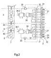
- FIG. 2 another embodiment of a texturing machine is shown. Here, a detail of a plan view of the embodiment is shown.
- the Embodiment of FIG. 2 is constructed substantially identical to the previous embodiment of FIG. In that regard, the arrangement of the processing units is constructed identically within a processing point, so that reference is made to the preceding description.
- FIG. 2 In the plan view shown in Fig. 2, only the thread inlet of the machine with the gate 7 and the inlet module 3 is shown. The process module 2 and the winding module 1 are not shown here. A total of 12 processing points are shown side by side. In this case, in each case the supply bobbins 8 of three juxtaposed processing points are arranged one above the other in the gate 7, as shown in FIG. 1. For the sake of clarity, however, the yarn path in FIG. 2 is not shown.
- the thread 36 of each of a master coil 8 of the gate 7 deducting first delivery mechanisms 10 are arranged side by side.
- a first delivery mechanism 10 is provided.
- the first delivery mechanism 10 in each case consists of a single drive 27, which is coupled to a godet 23.
- the godet 23 is associated with an overflow roller 24.
- the group converter 30 supplies the individual drives 27 of a total of six delivery mechanisms of a plurality of processing stations. In each case, six processing stations form a section, which are controlled by means of a field control 34. Thus, the group converter 30 is connected to the field controller 34.1 of the first section I of processing stations. Accordingly, the individual drives 27 of the delivery mechanisms 10 of the second section II are controlled via a further group converter 30, which in turn is coupled to the associated field control 34.2.
- the field controls 34.1 and 34.2 are connected to other sacrificeumrichtem or control units or drive units for controlling the processing points.
- the individual drives 27 a section is further associated with a control unit 33 which is connected to each of the individual drives 27 associated switching elements 32 of a section.
- the individual drives 27 furthermore have a sensor 31, which are connected to the control unit 33.
- the controller 33 is also coupled to the field controller 34.
- the field controls 34.1 and 34.2 as well as other adjacent field controls of the texturing machine are coupled to a central machine control (not shown here).
- the individual drives 27 of the first delivery mechanisms 10 per section are controlled by a group converter 30 with a predetermined setpoint frequency.
- the group converter 30 and the control unit 33 by the field controller 34 the corresponding desired frequency, which corresponds to a certain withdrawal speed of the threads from the supply spools 8, given.
- the corresponding desired frequency which corresponds to a certain withdrawal speed of the threads from the supply spools 8, given.
- each of the individual drives 27 is accelerated due to the particular asynchronous unit contained.
- a predetermined peripheral speed is set by the synchronizing unit of the individual drives 27 on each of the delivery mechanisms 10.
- the relevant individual drive 27 is switched off by the group converter 30 via the sensor 31 to the control unit 33 and the switching element 32.
- a comparison between the actual state signaled by the sensor 31 and a desired state output by the field control 34 takes place in the control device 33.
- the relevant switching element 32 is activated by the control device 33.
- the texturing machine By trained in the individual drives 27 synchronizing units and asynchronous units an independent starting and adjusting the desired peripheral speeds is ensured at the delivery works. Thus, a high uniformity of the yarn treatment is achieved in each of the processing points of the texturing machine, without reducing the flexibility in the control of the individual processing points.
- the texturing machine according to the invention combines the advantages of a group drive for processing units of the same function with the advantages of a processing point controlled by individually driven processing units.
Description
Die Erfindung betrifft eine Texturiermaschine zum Strecktexturieren einer Vielzahl von synthetischen Fäden gemäß dem Oberbegriff des Anspruchs 1.The invention relates to a texturing machine for draw texturing a multiplicity of synthetic threads according to the preamble of claim 1.
Eine gattungsgemäße Texturiermaschine ist aus der DE 100 26 942 A1 bekannt.A generic texturing machine is known from DE 100 26 942 A1.
Zum Strecktexturieren einer Vielzahl von Fäden besitzen derartige Texturiermaschinen eine entsprechende Vielzahl von Bearbeitungsstellen auf. Jede der Bearbeitungsstellen enthält mehrere Prozeßaggregate wie beispielsweise Lieferwerke, Falschdralltexturieraggregate und Aufwickeleinrichtungen, durch welche der Faden innerhalb der Bearbeitungsstelle gefördert, texturiert, verstreckt und zu einer Spule aufgewickelt wird. Zum Antreiben der Prozeßaggregate sind grundsätzlich zwei unterschiedliche Varianten bekannt. Bei einer ersten Variante werden alle Prozeßaggregate einer Gruppe beispielsweise alle ersten Lieferwerke der Bearbeitungsstellen gemeinsam durch einen Antrieb synchron angetrieben. Diese Variante besitzt jedoch generell den Nachteil, daß keine individuelle Steuerung der Bearbeitungsstellen möglich ist. Zur Vermeidung derartiger Nachteile ist aus der DE 100 26 942 eine Antriebsvariante bekannt, bei welcher die Prozeßaggregate durch Einzelantriebe innerhalb der Bearbeitungsstelle angetrieben werden. Dabei werden die Einzelantriebe einer Gruppe von Prozeßaggregaten benachbarter Bearbeitungsstellen wie beispielsweise alle Einzelantriebe der ersten Lieferwerke durch einen Gruppenumrichter gesteuert. Es hat sich nun jedoch herausgestellt, daß die individuelle Ansteuerung der Bearbeitungsstellen dazu führt, daß die Einzelantriebe der Prozeßaggregate unabhängig voneinander des öfteren an- und abgeschaltet werden. Dabei muß sichergestellt sein, daß die Einzelantriebe einer Gruppe von Prozeßaggregaten im Betriebszustand jeweils gleiche Betriebsparameter wie beispielsweise Antriebsdrehzahl aufweisen.For stretch texturing a plurality of threads, such texturing machines have a corresponding plurality of processing locations. Each of the processing stations includes a plurality of processing units, such as feeders, false twist texturing units and winders, through which the yarn is conveyed, textured, drawn and wound into a bobbin within the processing station. To drive the processing units basically two different variants are known. In a first variant, all processing units of a group, for example, all first delivery mechanisms of the processing stations are driven synchronously by a drive. However, this variant generally has the disadvantage that no individual control of the processing points is possible. To avoid such disadvantages, a drive variant is known from DE 100 26 942, in which the processing units are driven by individual drives within the processing point. In this case, the individual drives of a group of processing units of adjacent processing stations, such as all individual drives of the first supply plants are controlled by a group converter. However, it has now been found that the individual control of the processing points leads to the fact that the individual drives of the processing units are switched on and off independently of each other frequently. It must be ensured that the individual drives of a group of process units in the operating state each have the same operating parameters such as drive speed.
Es ist daher Aufgabe der Erfindung, eine Texturiermaschine der eingangs genannten Art derart weiterzubilden, daß selbst nach einem Abschalten einzelner Einzelantriebe die Prozeßaggregate einer Funktionsgruppe mehrerer Bearbeitungsstellen ohne größeren Steuerungsaufwand stets in einem bestimmten Betriebszustand betrieben werden können.It is therefore an object of the invention to develop a texturing machine of the type mentioned in such a way that even after a shutdown of individual drives, the process units of a functional group of several processing stations can be operated without major control effort always in a specific operating condition.
Diese Aufgabe wird erfindungsgemäß dadurch gelöst, daß der elektrische Einzelantrieb des Prozeßaggregates eine Asynchroneinheit zum Anlaufen bis zu einer vorgegebenen Sollfrequenz und eine Synchroneinheit zum Einhalten der vorgegebenen Sollfrequenz aufweist.This object is achieved in that the electric drive unit of the process unit has an asynchronous unit for starting up to a predetermined target frequency and a synchronization unit for maintaining the predetermined target frequency.
Die Erfindung besitzt somit den Vorteil, daß die Ansteuerung der Einzelantriebe durch einen Gruppenumrichter auf einfache Art derart möglich ist, daß jedem Einzelantrieb lediglich eine Sollfrequenz aufgegeben wird. Die Sollfrequenz bildet dabei den für das Prozeßaggregat erforderlichen Betriebszustand. In dem Einzelantrieb sorgt die Asynchroneinheit dafür, daß nach dem Einschalten der Einzelantrieb unmittelbar anläuft bis die Sollfrequenz erreicht ist. Bei Erreichen der Sollfrequenz tritt die Synchroneinheit des Einzelantriebes in Aktion und verhindert, daß das Prozeßaggregat mit einer von der Sollfrequenz abweichenden Frequenz angetrieben wird. Das Prozeßaggregat gelangt somit selbsttätig in einen der Sollfrequenz entsprechenden Betriebszustand. Damit ist es möglich, durch einen Gruppenumrichter eine Vielzahl von Einzelantrieben auf einfache Weise zu steuern. Die Prozeßaggregate einer Funktionsgruppe können somit nach jedem Zuschalten im Betriebszustand mit den jeweils vorgegebenen Sollparametern sicher betrieben werden. Damit ist die Gleichbehandlung aller Fäden in den Bearbeitungsstellen gewährleistet.The invention thus has the advantage that the control of the individual drives by a group converter in a simple way is possible such that each individual drive only a nominal frequency is abandoned. The setpoint frequency forms the operating state required for the processing unit. In the single drive, the asynchronous ensures that after switching on the single drive starts immediately until the target frequency is reached. Upon reaching the target frequency, the synchronous unit of the single drive comes into action and prevents the process unit is driven at a different frequency from the nominal frequency. The process unit thus automatically enters an operating state corresponding to the desired frequency. This makes it possible to easily control a large number of individual drives by means of a group converter. The processing units of a functional group can thus be safely operated after each connection in the operating state with the respective predetermined nominal parameters. This ensures the equal treatment of all threads in the processing points.
Grundsätzlich können die elektrischen Einzelantriebe sowohl als Asynchronmotoren oder als Synchronmotoren ausgebildet sein. Für den Fall, daß die Asynchroneinheit des Einzelantriebes durch den Asynchronmotor gebildet wird, enthält der Asynchronmotor einen Feldmagneten als Synchroneinheit. Der Feldmagnet wird vorzugsweise durch mehrere Permanentmagnete gebildet, welche an dem Rotor des Asynchronmotors befestigt sind. Damit wird erreicht, daß der Asynchronmotor nach der Beschleunigungsphase selbsttätig die vorgegebene Sollfrequenz einhält. Der Feldmagnet stellt sicher, daß der Rotor synchron zu dem Drehfeld des Stators des Asynchronmotors läuft. Diese Weiterbildung der Erfindung ist insbesondere für Prozeßaggregate geeignet, die ein relativ hohes Anlaufmoment erfordern.In principle, the individual electrical drives can be designed both as asynchronous motors or as synchronous motors. In the event that the asynchronous unit of the single drive is formed by the asynchronous motor, the asynchronous motor contains a field magnet as a synchronizing unit. The field magnet is preferably formed by a plurality of permanent magnets, which are attached to the rotor of the induction motor. This ensures that the asynchronous motor automatically follows the predetermined setpoint frequency after the acceleration phase. The field magnet ensures that the rotor runs synchronously with the rotating field of the stator of the asynchronous motor. This development of the invention is particularly suitable for processing units that require a relatively high starting torque.
Bevorzugt wird die Synchroneinheit durch einen Synchronmotor gebildet, welcher eine Hilfswicklung am Rotor als Asynchroneinheit aufweist. Damit ist sichergestellt, daß bei Ansteuerung des Einzelantriebes mit einer fest vorgegebenen Sollfrequenz der Synchronmotor ohne Verzögerung anläuft, bis der Rotor des Synchronmotors im Einklang mit dem Drehfeld des Stators ist.Preferably, the synchronous unit is formed by a synchronous motor having an auxiliary winding on the rotor as an asynchronous unit. This ensures that when driving the single drive with a fixed predetermined frequency of the synchronous motor starts without delay until the rotor of the synchronous motor is in line with the rotating field of the stator.
Um ein individuelles Ein- und Abschalten der Bearbeitungsstellen unabhängig voneinander zu ermöglichen, ist gemäß einer besonders vorteilhaften Weiterbildung der Erfindung jeder der Einzelantriebe der Gruppe von Prozeßaggregaten über ein steuerbares Schaltelement mit dem Gruppenumrichter verbunden. Damit kann ohne Beeinflussung benachbarter Einzelantriebe und Prozeßaggregate einer oder mehrere der dem Gruppenumrichter zugeordneten Einzelantrieb abgeschaltet werden.In order to enable an individual switching on and off of the processing points independently of each other, each of the individual drives of the group of process units is connected via a controllable switching element with the group converter according to a particularly advantageous embodiment of the invention. This can be switched off without influencing adjacent individual drives and process units one or more of the group converter associated with individual drive.
Darüber hinaus ist von Vorteil, wenn jeder der Einzelantriebe einen Sensor zur Drehzahlüberwachung aufweist, der mit einem die Schaltelemente steuernden Steuergerät verbunden ist. So kann vorteilhaft durch einen Ist-Soll-Vergleich eine Überbelastung der Einzelantriebe vermieden werden.Moreover, it is advantageous if each of the individual drives has a sensor for speed monitoring, which is connected to a control element controlling the switching elements. Thus, an overload of the individual drives can be advantageously avoided by an actual-target comparison.
Um beispielsweise beim Anlegen der Fäden in den Bearbeitungsstellen von einer Anlegegeschwindigkeit in eine Betriebsgeschwindigkeit umzuschalten, ist gemäß einer besonders bevorzugten Weiterbildung der Erfindung das Steuergerät und der Gruppenumrichter mit einer übergeordneten Maschinensteuerung verbunden.In order to switch, for example, when applying the threads in the processing points of a contact speed in an operating speed, the control unit and the group converter is connected to a higher-level machine control according to a particularly preferred embodiment of the invention.
Bei Verwendung mehrerer Einzelantriebe für mehrere Gruppen von Prozeßaggregaten ist den Einzelantrieben einer Gruppe von Prozeßaggregaten jeweils ein Gruppenumrichter zugeordnet. Dabei sind alle Gruppenumrichter mit der Maschinensteuerung gekoppelt. Zur Erhöhung der Flexibilität einer Texturiermaschine wird gemäß einer weiteren vorteilhaften Ausführung der Erfindung vorgeschlagen, die Vielzahl der Bearbeitungsstellen in eine oder mehrere Sektionen jeweils mehreren Bearbeitungsstellen aufzuteilen. Dabei sind die Gruppenumrichter der Sektion mit einer der Sektion zugeordneten Feldsteuerung verbunden. Die Prozeßaggregate der Bearbeitungsstellen der betreffenden Sektion können somit unabhängig von den Prozeßaggregaten der Bearbeitungsstellen der benachbarten Sektionen gesteuert werden.When using several individual drives for several groups of processing units, the individual drives of a group of process units each have a group converter is assigned. All group inverters are coupled with the machine control. In order to increase the flexibility of a texturing machine, it is proposed according to a further advantageous embodiment of the invention to divide the plurality of processing stations into one or more sections each of a plurality of processing stations. The group inverters of the section are connected to a field control assigned to the section. The process units of the processing points of the respective section can thus be controlled independently of the processing units of the processing points of the adjacent sections.
Die durch Einzelantriebe angetriebenen Prozeßaggregate können vorteilhaft durch ein erstes Lieferwerk und/oder ein zweites Lieferwerk und/oder ein drittes Lieferwerk pro Bearbeitungsstelle gebildet sein. Damit ist die Möglichkeit gegeben, die Fadengeschwindigkeit sowie das Verstreckverhältnis zum Verstrecken der Fäden exakt einzustellen und zu variieren.The process units driven by individual drives can advantageously be formed by a first delivery mechanism and / or a second delivery mechanism and / or a third delivery mechanism per processing point. This makes it possible to set and vary the thread speed and the draw ratio for drawing the threads exactly.
Die Gruppe der Prozeßaggregate, die durch Einzelantriebe angetrieben werden, können jedoch auch durch eine Treibwalze einer Aufwickeleinrichtung und/oder durch ein Falschdralltexturieraggregat pro Bearbeitungsstelle gebildet sein.However, the group of process units that are driven by individual drives can also be formed by a drive roller of a take-up device and / or by a false twist texturing unit per processing point.
Grundsätzlich sind alle rotierend angetriebenen Prozeßaggregate geeignet, die während dem Strecktexturieren der Fäden mit einer im wesentlichen vorgegebenen Sollfrequenz betrieben werden.In principle, all rotationally driven processing units are suitable, which are operated during the draw texturing of the threads with a substantially predetermined nominal frequency.
Im nachfolgenden ist ein Ausführungsbeispiel einer erfindungsgemäßen Texturiermaschine unter Hinweis auf die beigefügten Zeichnungen näher beschrieben.In the following, an embodiment of a texturing machine according to the invention is described in detail with reference to the accompanying drawings.
Es stellen dar
- Fig. 1
- eine schematische Seitenansicht eines ersten Ausführungsbeispiels einer erfindungsgemäßen Texturiermaschine
- Fig. 2
- schematisch ein Ausschnitt einer Draufsicht eines weiteren Ausführungsbeispiels einer Texturiermaschine
- Fig. 3
- schematisch ein Ausführungsbeispiel eines Einzelantriebes für ein Lieferwerk
- Fig. 4
- schematisch ein weiteres Ausführungsbeispiel eines Einzelantriebes für ein Lieferwerk
- Fig. 5
- ein Ausführungsbeispiel eines Einzelantriebes für eine Treibwalze einer Aufwickeleinrichtung
- Fig. 1
- a schematic side view of a first embodiment of a texturing machine according to the invention
- Fig. 2
- schematically a section of a plan view of another embodiment of a texturing machine
- Fig. 3
- schematically an embodiment of a single drive for a delivery plant
- Fig. 4
- schematically another embodiment of a single drive for a delivery plant
- Fig. 5
- An embodiment of a single drive for a drive roller of a take-up device
In Fig. 1 ist schematisch ein erstes Ausführungsbeispiel der erfindungsgemäßen Texturiermaschine gezeigt. Die Texturiermaschine besteht aus einen Einlaufinodul 3, einem Prozeßmodul 2 und einem Aufwickelmodul 1, die in einem Maschinengestell mit den Gestellteilen 4.1, 4.2 und 4.3 angeordnet sind. Das Einlaufmodul 3 wird durch das Gestellteil 4.1 und das Prozeßmodul 2 und das Aufwickelmodul 1 durch das Gestellteil 4.3 getragen. Das Gestellteil 4.1 und das Gestellteil 4.3 sind durch ein Gestellteil 4.2 verbunden, welches oberhalb des Einlaufmoduls 3 und des Prozeßmoduls 2 angeordnet ist. Zwischen dem Prozeßmodul 2 und dem Einlaufmodul 3 ist unterhalb des Gestellteils 4.2 ein Bediengang 5 gebildet. In dem Gestellteil 4.2 ist auf der zu dem Bediengang 5 hingewandten Seite das Prozeßmodul 2 und auf der gegenüberliegenden Seite das Aufwickelmodul 1 angeordnet. Längs des Aufwickelmoduls 1 ist ein Doffgang 6 vorgesehen. Die Texturiermaschine weist in Längsrichtung - in der Fig. 1 ist die Zeichnungsebene gleich der Querebene - eine Vielzahl von Bearbeitungsstellen auf, für jeweils einen Faden pro Bearbeitungsstelle. Die Aufwickeleinrichtungen 18 nehmen eine Breite von drei Bearbeitungsstellen ein. Daher sind jeweils drei Aufwickeleinrichtungen 18 - hierauf wird später eingegangen - in einer Säule übereinander in dem Aufwickelmodul 1 angeordnet.In Fig. 1, a first embodiment of the texturing machine according to the invention is shown schematically. The texturing machine consists of an
In der in Fig. 1 dargestellten Ansicht sind in dem Einlaufmodul 1 und dem Prozeßmodul 2 jeweils die Prozeßaggegate einer Bearbeitungsstelle gezeigt. Jede Bearbeitungsstelle weist somit mehrere in einem Fadenlauf hintereinander angeordnete Prozeßaggregate 10, 11, 12,13,14,15,16,17 und 18 auf.In the view shown in FIG. 1, the process gate of a processing station are respectively shown in the inlet module 1 and the
Eine erste Gruppe der Prozeßaggregate wird durch das erste Lieferwerk 10 pro Bearbeitungsstelle gebildet, das an dem Einlaufmodul 3 befestigt ist. Die benachbarten ersten Lieferwerke der benachbarten Bearbeitungsstellen sind nebeneinander (hier nicht dargestellt) angeordnet, wobei jedem ersten Lieferwerk 10 eine Vorlagespule 8 in dem Gatter 7 zugeordnet ist. Neben der Vorlagenspule 8 ist pro Bearbeitungsstelle eine Reservespule 43 in dem Gatter 7 vorgesehen. Pro Bearbeitungsstelle wird ein Faden 36 über mehrere Umlenkfadenführer 9.1 und 9.2 durch das erste Lieferwerk 10 abgezogen.A first group of process units is formed by the
Anhand des Fadenlaufs des Fadens 36 werden nachfolgend die weiteren Prozeßaggregate einer Bearbeitungsstelle beschrieben. In Fadenlaufrichtung hinter dem ersten Lieferwerk 10 befindet sich eine langgestreckte Primärheizeinrichtung 11, durch welche der Faden 36 läuft, wobei der Faden 36 auf eine bestimmte Temperatur erwärmt wird. Die Primärheizeinrichtung 11 könnte dabei als Hochtemperaturheizer ausgeführt sein, bei dem die Heizoberflächentemperatur über 300 °C liegt. In Fadenlaufrichtung hinter der Primärheizeinrichtung 11 ist eine Kühleinrichtung 12 vorgesehen. Die Primärheizeinrichtung 11 und die Kühleinrichtung 12 sind in einer Ebene hintereinander angeordnet und werden durch das Gestellteil 4.2 oberhalb des Bediengangs 5 gehalten. Im Eingangsbereich der Primärheizeinrichtung 11 ist eine Umlenkrolle 9.3 angeordnet, so daß der Faden 36 den Bediengang 5 in einem V-förmigen Fadenlauf überquert.Based on the yarn path of the
Auf der zum Einlaufmodul 3 gegenüberliegenden Seite des Bediengangs 5 ist das Prozeßmodul 2 an dem Gestellteil 4.3 angeordnet. Das Prozeßmodul 2 trägt in Fadenlaufrichtung untereinander ein Falschdralltexturieraggregat 13, ein zweites Lieferwerk 14 und ein drittes Lieferwerk 15. Dabei wird der Faden 36 vom Ausgang der Kühleinrichtung 12, die vorzugsweise durch eine Kühlschiene oder ein Kühlrohr gebildet wird, zu dem Falschdralltexturieraggregat 13 geführt. Das Falschdralltexturieraggregat 13, das beispielsweise durch mehrere sich überlappende Friktionsscheiben gebildet sein kann, wird durch den Falschdrallantrieb 26 angetrieben. Der Falschdrallantrieb 26 ist als ein Einzelantrieb 27 ausgebildet, der ebenfalls an dem Prozeßmodul 2 angebracht ist.On the side opposite the
Durch das zweite Lieferwerk 14 wird der Faden 36 aus der Falschdrallzone abgezogen, die sich zwischen dem Falschdralltexturieraggregat 13 und dem ersten Lieferwerk 10 bildet. Das zweite Lieferwerk 14 und das erste Lieferwerk 10 werden zum Verstrecken des Fadens 36 in der Falschdrallzone mit einer Differenzgeschwindigkeit angetrieben.By the
Unterhalb des zweiten Lieferwerks 14 ist das dritte Lieferwerk 15 angeordnet, welches den Faden 36 unmittelbar in eine Sekundärheizeinrichtung 16 führt. Die Sekundärheizeinrichtung 16 ist hierzu an der Unterseite des Gestellteils 4.3 und somit unterhalb des Prozeßmoduls 2 und des Aufwickelmoduls 1 angeordnet. Die Sekundärheizeinrichtung 16 bildet den Fadenübergang von dem Prozeßmoduls zu dem Aufwickelmodul 1. Durch die Integration des Prozeßmoduls 2, der Sekundärheizeinrichtung 16 und des Aufwickelmoduls 1 in dem Gestellteil 4.3 wird ein sehr kurzer Fadenlauf realisiert, der im wesentlichen U-förmig ausgebildet ist. Auf der Unterseite des Aufwickelmoduls 1 ist dazu ein viertes Lieferwerk 17 angeordnet, welches unmittelbar den Faden 36 aus der Sekundärheizeinrichtung 16 abzieht und nach Umlenkung des Fadens 36 zu der Aufwickeleinrichtung 18 führt. Das dritte Lieferwerk 15 und das vierte Lieferwerk 17 werden mit einer derartigen Differenzgeschwindigkeit angetrieben, daß eine Schrumpfbehandlung des Fadens 36 innerhalb der Sekundärheizeinrichtung 16 möglich ist. Die Sekundärheizeinrichtung 16 wird hierbei durch ein diphylbeheizten Kontaktheizer gebildet. Hierzu ist die Sekundärheizeinrichtung 16 um einen Winkel α gegenüber einer Horizontalen geneigt angeordnet. Der Winkel liegt im Bereich zwischen 5 bis 45 °. Damit wird sichergestellt, daß der Faden 36 innerhalb des Heizkanals der Sekundärheizeinrichtung 16 eine gleichmäßige durch Kontakt bewirkte Erwärmung erhält.Below the
Die Aufwickeleinrichtung 18 ist bei diesem Ausführungsbeispiel schematisch durch eine Changierung 20, eine Treibwalze 19 und eine Spule 21 gekennzeichnet. Die Aufwickeleinrichtung 18 enthält zudem ein Hülsenmagazin 22 um einen automatischen Spulenwechsel auszuführen. Die zum Auswechseln der Vollspulen erforderlichen Hilfseinrichtungen sind hier nicht näher dargestellt.The winding
Die Lieferwerke 10, 14, 15 und 17 sind in diesem Ausführungsbeispiel identisch aufgebaut, und werden jeweils durch eine Galette 23 und eine der Galetten zugeordneten Überlaufrolle 24 gebildet. Die Galette 23 wird über einen Galettenantrieb 25 angetrieben. Die Überlaufrolle 24 ist frei drehbar gelagert, so daß der Faden 36 mit mehreren Umschlingungen über die Galette 23 und die Überlaufrolle 24 geführt wird.The
Bei dem in Fig. 1 dargestellten Ausführungsbeispiel der Texturiermaschine ist der Galettenantrieb 25 des ersten Lieferwerkes 10 als ein Einzelantrieb 27 ausgebildet. Der Einzelantrieb 27, dessen Aufbau nachfolgend noch näher erläutert wird, ist über ein Schaltelement 32 mit einem Gruppenumrichter 30 gekoppelt. Dem Gruppenumrichter 30 sind ebenfalls die benachbarten Einzelantriebe der hier nicht dargestellten benachbarten ersten Lieferwerke der benachbarten Bearbeitungsstellen zugeordnet. So können beispielsweise alle Einzelantriebe der ersten Lieferwerke innerhalb der Texturiermaschine einem gemeinsamen Gruppenumrichter 30 zugeordnet sein. Der Gruppenumrichter 30 ist mit einer zentralen Maschinensteuerung 44 verbunden. Das erste Lieferwerk 10 stellt somit eine erste Funktionsgruppe von Prozeßaggregaten dar, die durch Einzelantriebe 27 innerhalb der Maschine angetrieben werden.In the embodiment of the texturing machine shown in FIG. 1, the
Eine zweite Funktionsgruppe von Prozeßaggregaten stellen die Falschdralltexturieraggregate 13 dar. Die Falschdrallantriebe 26 sind ebenfalls als Einzelantriebe 27 ausgebildet, die einem zweiten Gruppenumrichter 45 zugeordnet sind. Dabei erfolgt die Anbindung der Einzelantriebe 27 einen zweiten Gruppenumrichter 45 ebenfalls durch ein Schaltelement 32. Der zweite Gruppenumrichter 45 ist ebenfalls mit der Maschinensteuerung 44 verbunden.A second functional group of process units represent the false
Die Antriebe und Antriebssteuerung der übrigen Prozeßaggregate ist hier nicht näher erläutert und könnte beispielsweise ebenfalls durch Einzelantriebe mit Steuerung über Gruppenumrichter oder durch einzeln gesteuerte Antriebe ausgebildet sein.The drives and drive control of the other process units is not explained here in detail and could for example also be formed by individual drives with control via group converter or by individually controlled drives.
Im Betrieb werden die Einzelantriebe 27 der Lieferwerke 10 und der Falschdralltexturieraggregate 13 über die zugeordneten Gruppenumrichter 30 und 45 mit einer durch die Maschinensteuerung 44 definierten Sollfrequenz gesteuert, so daß das Lieferwerk 10 eine bestimmte Umfangsgeschwindigkeit zur Förderung des Fadens 36 aufweist und so daß das Falschdralltexturieraggregat 13 ebenfalls ein zum Texturieren des Fadens erforderliche Antriebsdrehzahl erhält. Der Faden 36 wird in der Bearbeitungsstelle bekannterweise gefördert, verstreckt, texturiert und zu einer Spule 21 aufgewickelt. Für den Fall, daß in der dargestellten Bearbeitungsstelle eine Störung beispielsweise durch Fadenriß eintritt, werden die Einzelantriebe 27 des Lieferwerkes 10 und des Falschdralltexturieraggregates 13 durch die Schaltelemente 32 von dem jeweiligen Gruppenumrichter 30 oder 45 getrennt. Das erste Lieferwerk 10 und das Falschdralltexturieraggregat 13 sind ausgeschaltet. Benachbarte Bearbeitungsstellen bleiben von dieser Aktion unbeeinflußt. Die in den Gruppenumrichtern 30 und 45 zugeordneten Einzelantriebe bleiben im unveränderten Betriebszustand.In operation, the individual drives 27 of the
Nachdem die Störung in der Bearbeitungsstelle beseitigt ist, erfolgt über die Schaltelemente 32 ein erneutes Zuschalten zu den Gruppenumrichter 30 und 45, so daß ein Ansteuern der Einzelantriebe 27 wieder möglich ist. Den Einzelantrieben 27 wird so die Sollfrequenz aufgegeben.After the disturbance in the processing station has been eliminated, a renewed connection to the
Um das An- und Abschalten sowie das Anlaufen und das Halten im Betriebszustand der Einzelantriebe 27 ohne größeren Steuerungsaufwand zu ermöglichen, besitzen die Einzelantriebe 27 jeweils eine Synchroneinheit und eine Asynchroneinheit. In Fig. 3 ist ein ersten Ausführungsbeispiel eines Einzelantriebes 27 dargestellt. Hierbei ist der Einzelantrieb 27 als ein Asynchronmotor 35 ausgebildet. Der Asynchronmotor 35 stellt somit die Asynchroneinheit 29 bestehend aus einer Statorwicklung 39 und einer Rotorwicklung 41 dar. Hierzu ist die Rotorwicklung 41 an dem Rotor 40 angebracht. Innerhalb der Statorwicklung 39 trägt der Rotor 40 einen Feldmagneten 36, der zusammen mit der Statorwicklung 39 die Synchroneinheit 28 darstellt. Der Feldmagnet 36 wird hierbei durch mehrere Permanentmagnete gebildet, die am Umfang des Rotors 40 befestigt sind. Der Rotor 40 ist an einem aus dem Motorgehäuse herausragenden Ende mit der Galette 23 des ersten Lieferwerkes 10 verbunden.In order to enable switching on and off as well as start-up and holding in the operating state of the individual drives 27 without major control effort, the individual drives 27 each have a synchronizing unit and an asynchronous unit. In Fig. 3, a first embodiment of a
Zum Anlaufen des Asynchronmotors 35 wird über den Gruppenumrichter 30 eine Sollfrequenz aufgegeben. Nach der Bestromung der Statorwicklung 31 wird der Rotor 40 beschleunigt. Sobald die Drehfrequenz des Rotors 40 der Sollfrequenz entspricht, tritt eine Kopplung zwischen dem Drehfeld der Statorwicklung 39 und der Drehfrequenz des Rotors 40 durch den Feldmagnet 36 ein. Der Einzelantrieb 27 verhält sich im Betriebszustand entsprechend einer Synchronmaschine. Damit ist sichergestellt, daß die durch den Gruppenumrichter 30 vorgegebene Sollfrequenz selbsttätig von dem angesteuerten Einzelantrieb 28 eingestellt wird. Dies ist insbesondere für die als Lieferwerke in der Texturiermaschine angeordneten Prozeßaggregate wichtig. Somit wird in jeder Bearbeitungsstelle der Faden unter gleichen Bedingungen gefördert und verstreckt.To start the
In Fig. 4 ist ein weiteres Ausführungsbeispiel eines Einzelantriebes 27 mit einer Synchroneinheit 28 und einer Asynchroneinheit 29 dargestellt. Die Bauteile gleicher Funktion sind hierbei mit identischen Bezugszeichen versehen. Die Synchroneinheit 28 wird durch ein Synchronmotor 38 gebildet. Hierzu weist der Synchronmotor 38 eine Statorwicklung 39 und einen Rotor 40 mit zumindest einem Permanentmagnet 37 auf. In diesem Fall ist die Drehfrequenz des Rotors 40 gleich der Sollfrequenz, so daß der Rotor 40 synchron mit dem Drehfeld der Statorwickler umläuft. Um nach einem Abschalten des Einzelantriebes 27 ein Anlaufen ohne Veränderung der Sollfrequenz zu ermöglichen, besitzt der Synchronmotor 38 eine Asynchroneinheit 29 auf, die durch eine Hilfswicklung 42 am Rotor 40 und der Statorwicklung 39 gebildet ist. Die Hilfswicklung 42 ist innerhalb der Statorwicklung 39 angeordnet. Somit ist sichergestellt, daß der Rotor 40 bei vorgegebener Sollfrequenz der Statorwicklung 39 beschleunigt wird.4, a further embodiment of a
Die in den Fig. 3 und 4 gezeigten Ausführungsbeispiele des Einzelantriebes sind vorzugsweise zum Antreiben der Lieferwerke einer Texturiermaschine oder zum Antreiben eines Falschdralltexturieraggregates geeignet. In Fig. 5 ist ein weiteres Ausführungsbeispiel eines Einzelantriebes 27 gezeigt, das vorzugsweise zum Antreiben einer Treibwalze 19 in einer Aufwickeleinrichtung 18 geeignet ist. Hierzu wird der Walzenmantel der Treibwalze 19 unmittelbar durch den innerhalb der Treibwalze 19 angeordneten Einzelantrieb 27 angetrieben. Dazu beisitzt der Einzelantrieb 27 einen mantelförmigen Rotor 40. An der Innenseite des mantelförmigen Rotors 40 ist die Rotorwicklung 41 angebracht. Der Rotorwicklung 41 gegenüberliegend ist eine Statorwicklung 39 an einer feststehenden Achse 46 befestigt. Die Statorwicklung 39 erstreckt sich in axialer Richtung über die Rotorwicklung 41 hinaus um einen am mantelförmigen Rotor 40 befestigten Feldmagneten 36 zu überdecken. Der Feldmagnet 36 und die Statorwicklung 39 bilden somit die Synchroneinheit 28 des Einzelantriebes 27. Die Asynchroneinheit 29 ist hierbei durch den Aufbau als Asynchronmotor 35 gebildet. Die Funktionsweise des in Fig. 5 dargestellten Ausführungsbeispieles ist identisch zu den in Fig. 3 und 4 beschriebenen Einzelantrieben.The embodiments of the single drive shown in FIGS. 3 and 4 are preferably suitable for driving the delivery mechanisms of a texturing machine or for driving a false twist texturing aggregate. In Fig. 5, a further embodiment of a
In Fig. 2 ist ein weiteres Ausführungsbeispiel einer Texturiermaschine dargestellt. Hierbei ist ein Ausschnitt einer Draufsicht des Ausführungsbeispiels gezeigt. Das Ausführungsbeispiel nach Fig. 2 ist im wesentlichen identisch zu dem vorhergehenden Ausführungsbeispiel nach Fig. 1 aufgebaut. Insoweit ist die Anordnung der Prozeßaggregate innerhalb einer Bearbeitungsstelle identisch aufgebaut, so daß zu der vorhergehenden Beschreibung Bezug genommen wird.2, another embodiment of a texturing machine is shown. Here, a detail of a plan view of the embodiment is shown. The Embodiment of FIG. 2 is constructed substantially identical to the previous embodiment of FIG. In that regard, the arrangement of the processing units is constructed identically within a processing point, so that reference is made to the preceding description.
Bei der in Fig. 2 dargestellten Draufsicht ist nur der Fadeneinlauf der Maschine mit dem Gatter 7 und dem Einlaufinodul 3 gezeigt. Das Prozeßmodul 2 und das Aufwickelmodul 1 sind hierbei nicht dargestellt. Insgesamt sind 12 Bearbeitungsstellen nebeneinander gezeigt. Dabei sind in dem Gatter 7 jeweils die Vorlagespulen 8 von drei nebeneinander angeordneten Bearbeitungsstellen etagenmäßig übereinander angeordnet wie aus Fig. 1 ersichtlich. Der Übersicht halber ist der Fadenlauf in Fig. 2 jedoch nicht gezeigt.In the plan view shown in Fig. 2, only the thread inlet of the machine with the
An dem Einlaufmodul 3 sind die den Faden 36 von jeweils einer Vorlagenspule 8 des Gatters 7 abziehenden ersten Lieferwerke 10 nebeneinander angeordnet. Pro Bearbeitungsstelle ist ein erstes Lieferwerk 10 vorgesehen. Das erste Lieferwerk 10 besteht dabei jeweils aus einem Einzelantrieb 27, welcher mit einer Galette 23 gekoppelt ist. Der Galette 23 ist eine Überlaufrolle 24 zugeordnet.At the
Zur Steuerung ist der Einzelantrieb 27 über ein Schaltelement 32 mit einem Gruppenumrichter 30 verbunden. Der Gruppenumrichter 30 versorgt die Einzelantriebe 27 von insgesamt sechs Lieferwerken mehrerer Bearbeitungsstellen. Hierbei bilden jeweils sechs Bearbeitungsstellen eine Sektion, die mittels einer Feldsteuerung 34 gesteuert werden. Somit ist der Gruppenumrichter 30 mit der Feldsteuerung 34.1 der ersten Sektion I von Bearbeitungsstellen verbunden. Dementsprechend sind die Einzelantriebe 27 der Lieferwerke 10 der zweiten Sektion II über einen weiteren Gruppenumrichter 30 gesteuert, der wiederum mit der zugeordneten Feldsteuerung 34.2 gekoppelt ist.For controlling the
Die Feldsteuerungen 34.1 und 34.2 sind mit weiteren Gruppenumrichtem oder Steuergeräten oder Antriebseinheiten zur Steuerung der Bearbeitungsstellen verbunden.The field controls 34.1 and 34.2 are connected to other Gruppenumrichtem or control units or drive units for controlling the processing points.
Den Einzelantrieben 27 einer Sektion ist desweiteren ein Steuergerät 33 zugeordnet, das mit jedem den Einzelantrieben 27 zugeordneten Schaltelementen 32 einer Sektion verbunden ist. Die Einzelantriebe 27 weisen desweiteren einen Sensor 31 auf, welche mit dem Steuergerät 33 verbunden sind. Das Steuergerät 33 ist zudem mit der Feldsteuerung 34 gekoppelt.The individual drives 27 a section is further associated with a
Die Feldsteuerungen 34.1 und 34.2 sowie weitere benachbarte Feldsteuerungen der Texturiermaschine sind mit einer zentralen Maschinensteuerung (hier nicht dargestellt) gekoppelt.The field controls 34.1 and 34.2 as well as other adjacent field controls of the texturing machine are coupled to a central machine control (not shown here).
Bei der in Fig. 2 gezeigten Texturiermaschine werden im Betriebszustand die Einzelantriebe 27 der ersten Lieferwerke 10 pro Sektion durch einen Gruppenumrichter 30 mit einer vorgegebenen Sollfrequenz angesteuert. Hierzu wird dem Gruppenumrichter 30 sowie dem Steuergerät 33 durch die Feldsteuerung 34 die entsprechende Sollfrequenz, welche eine bestimmte Abzugsgeschwindigkeit der Fäden von den Vorlagespulen 8 entspricht, vorgegeben. Bei Prozeßbeginn wird jeder der Einzelantriebe 27 aufgrund der jeweils enthaltenen Asynchroneinheit beschleunigt. Sobald die Drehfrequenz des Rotors die Sollfrequenz erreicht, wird durch die Synchroneinheit der Einzelantriebe 27 an jedem der Lieferwerke 10 eine vorgegebene Umfangsgeschwindigkeit eingestellt.In the texturing machine shown in FIG. 2, in the operating state, the individual drives 27 of the
Für den Fall, daß bei einem der Einzelantriebe 27 eine Störung auftritt, die eine unzulässige Abweichung von der Sollfrequenz zeigt, wird über den Sensor 31 dem Steuergerät 33 und dem Schaltelement 32 der betreffende Einzelantrieb 27 vom Gruppenumrichter 30 abgeschaltet. Hierzu findet in dem Steuergerät 33 ein Vergleich zwischen dem von dem Sensor 31 signalisierten Ist-Zustand mit einem von der Feldsteuerung 34 aufgegebenen Soll-Zustand statt. Bei unzulässiger Abweichung zwischen dem Ist-Zustand vom Soll-Zustand wird das betreffende Schaltelement 32 durch das Steuergerät 33 aktiviert. Hierbei erfolgt ein gegenseitiger Informationsaustausch zwischen dem Steuergerät 33 und der Feldsteuerung 34. Sobald die Störung beseitigt ist, wird über das Steuergerät 33 das entsprechende Schaltelement zur Ansteuerung des Einzelantriebes aktiviert. Die durch den Gruppenumrichter 30 benachbarten Einzelantriebe 27 bleiben dabei in ihrer Steuerung unbeeinflußt. Durch die in den Einzelantrieben 27 ausgebildeten Synchroneinheiten und Asynchroneinheiten ist ein selbständiges Anlaufen und Einstellen der gewünschten Umfangsgeschwindigkeiten an den Lieferwerken gewährleistet. Damit wird eine hohe Gleichmäßigkeit der Fadenbehandlung in jeder der Bearbeitungsstellen der Texturiermaschine erreicht, ohne die Flexibilität in der Ansteuerung der einzelnen Bearbeitungsstellen zu mindern. Damit vereinigt die erfindungsgemäße Texturiermaschine die Vorteile eines Gruppenantriebes für Prozeßaggregate gleicher Funktion mit den Vorteilen einer mit einzeln angetriebenen Prozeßaggregaten gesteuerten Bearbeitungsstelle.In the event that a malfunction occurs in one of the individual drives 27, which shows an impermissible deviation from the nominal frequency, the relevant
- 11
- AufwickelmodulRewinding
- 22
- Prozeßmodulprocess module
- 33
- EinlaufinodulEinlaufinodul
- 44
- Gestellteilframe part
- 55
- Bediengangservice aisle
- 66
- Doffgangdoffing aisle
- 77
- Gattergate
- 88th
- Vorlagespulesupply bobbin
- 99
- Umlenkrolleidler pulley
- 1010
- Erstes LieferwerkFirst delivery plant
- 1111
- Primärheizeinrichtungprimary heater
- 1212
- Kühleinrichtungcooling device
- 1313
- Falschdralltexturieraggregatfalse twist
- 1414
- Zweites LieferwerkSecond delivery mechanism
- 1515
- Drittes LieferwerkThird delivery plant
- 1616
- Sekundärheizeinrichtungsecondary heater
- 1717
- Viertes LieferwerkFourth delivery plant
- 1818
- Aufwickeleinrichtungtakeup
- 1919
- Treibwalzedrive roll
- 2020
- Changierungtraversing
- 2121
- SpuleKitchen sink
- 2222
- Hülsenmagazintube magazine
- 2323
- GaletteGalette
- 2424
- ÜberlaufrolleGuide roll
- 2525
- Galetteneinheitgalette
- 2626
- FalschdrallantriebFalse twist drive
- 2727
- Einzelantriebindividual drive
- 2828
- Synchroneinheitsynchronous unit
- 2929
- Asynchroneinheitasynchronous unit
- 3030
- Gruppenumrichtergroup frequency
- 3131
- Sensorsensor
- 3232
- Schaltelementswitching element
- 3333
- Steuergerätcontrol unit
- 3434
- Feldsteuerungfield control
- 3535
- Asynchronmotorasynchronous
- 3636
- Feldmagnetmagnetic field
- 3737
- Permanentmagnetpermanent magnet
- 3838
- Synchronmotorsynchronous motor
- 3939
- Statorwicklungstator
- 4040
- Rotorrotor
- 4141
- Rotorwicklungrotor winding
- 4242
- Hilfswicklungauxiliary winding
- 4343
- Reservespulereserve package
- 4444
- Maschinensteuerungmachine control
- 4545
- Zweiter GruppenumrichterSecond group converter
- 4646
- Achseaxis
Claims (13)
- Texturing machine for draw texturing a plurality of synthetic filament yarns with a corresponding plurality of processing stations, wherein the yarns in the processing stations are parallel advanced, textured, drawn, and wound by a plurality of processing units (10, 13, 14, 15, 18), wherein within the processing station at least one of the processing units (10) is associated with an electric individual drive (27), and wherein the individual drives (27) of the group of processing units (10) of adjacent processing stations are controllable by a group frequency changer (30), characterized in that the electric individual drive (27) of the processing unit (10) comprises an asynchronous unit (29) for starting up to a predetermined desired frequency and a synchronous unit (28) for maintaining the predetermined desired frequency.
- Texturing machine of claim 1, characterized in that the asynchronous unit (29) is formed by an asynchronous motor (35), which includes a field magnet (36) as a part of the synchronous unit (28).
- Texturing machine of claim 2, characterized in that the field magnet (36) is formed by one or more permanent magnets, which are arranged on the rotor (40) of the asynchronous motor (35).
- Texturing machine of claim 1, characterized in that the synchronous unit (28) is formed by a synchronous motor (38), which includes an auxiliary winding (42) on the rotor (40) as a part of the asynchronous unit (29).
- Texturing machine of one of claims 1 to 4, characterized in that each of the individual drives (27) of the group of processing units (10) of a plurality of processing stations connects via a controllable switching element (32) to the group frequency changer (30).
- Texturing machine of claim 5, characterized in that each of the individual drives (27) is provided with a sensor (31) for monitoring the rotational speed, and that the sensors (31) and the switching elements (32) connect to a control unit.
- Texturing machine of claim 6, characterized in that the control unit (33) and the group frequency changer (30) connect to a control unit (34), which is associated to the respective processing stations.
- Texturing machine of one of claims 1 to 7, characterized in that the individual drives (27) of a first group of processing units (10) are controllable by a first group frequency changer (30), and the individual drives (27) of a second group of processing units (13) by a second group frequency changer (45), and that the group frequency changers (30, 45) connect to a control system (44).
- Texturing machine of one of the foregoing claims, characterized in that the plurality of the processing stations are divided into one of more sections (I, II) with respectively a plurality of processing stations, and that the group frequency changers (30) of one of the sections connect to a field control system (34) associated to the section.
- Texturing machine of one of claims 1 to 9, characterized in that for each processing station, the group of processing units is formed by a first feed system (10) and/or a second feed system (14) and/or a third feed system (15).
- Texturing machine of claim 10, characterized in that at least one portion of the feed systems (10, 14, 15) is each formed by a godet unit with a godet (23) and a guide roll (24), with the godet (23) being coupled with the individual drive (27).
- Texturing machine of one of the foregoing claims, characterized in that for each processing station, the group of processing units is formed by a drive roll (19) of a takeup device (18).
- Texturing machine of one of the foregoing claims, characterized in that for each processing station, the group of processing units is formed by a false twist texturing unit (13).
Applications Claiming Priority (3)
| Application Number | Priority Date | Filing Date | Title |
|---|---|---|---|
| DE10207086A DE10207086A1 (en) | 2002-02-20 | 2002-02-20 | Textile texturing machine, has individual thread feed with frequency converter regulation of motor drive at work station |
| DE10207086 | 2002-02-20 | ||
| PCT/EP2003/001486 WO2003071016A1 (en) | 2002-02-20 | 2003-02-14 | Texturing machine |
Publications (2)
| Publication Number | Publication Date |
|---|---|
| EP1476594A1 EP1476594A1 (en) | 2004-11-17 |
| EP1476594B1 true EP1476594B1 (en) | 2006-08-30 |
Family
ID=27635181
Family Applications (1)
| Application Number | Title | Priority Date | Filing Date |
|---|---|---|---|
| EP03706508A Expired - Lifetime EP1476594B1 (en) | 2002-02-20 | 2003-02-14 | Texturing machine |
Country Status (9)
| Country | Link |
|---|---|
| US (1) | US6990795B2 (en) |
| EP (1) | EP1476594B1 (en) |
| KR (1) | KR100887209B1 (en) |
| CN (1) | CN100429341C (en) |
| AU (1) | AU2003208855A1 (en) |
| DE (2) | DE10207086A1 (en) |
| ES (1) | ES2269981T3 (en) |
| TW (1) | TWI304846B (en) |
| WO (1) | WO2003071016A1 (en) |
Families Citing this family (4)
| Publication number | Priority date | Publication date | Assignee | Title |
|---|---|---|---|---|
| DE10227290A1 (en) * | 2002-06-19 | 2004-01-08 | Barmag Ag | Device for guiding, treating and conveying at least one thread |
| CN103835039A (en) * | 2014-03-13 | 2014-06-04 | 无锡宏源机电科技有限公司 | Texturing machine |
| CN105986343B (en) * | 2015-02-12 | 2020-12-01 | 欧瑞康纺织有限及两合公司 | Deformation machine |
| US11736051B2 (en) * | 2021-08-05 | 2023-08-22 | Schweitzer Engineering Laboratories, Inc. | Synchronous motor startup configuration to synchronous mode at a field zero-crossing |
Family Cites Families (12)
| Publication number | Priority date | Publication date | Assignee | Title |
|---|---|---|---|---|
| DE3324243A1 (en) * | 1982-07-09 | 1984-02-16 | Barmag Barmer Maschinenfabrik Ag, 5630 Remscheid | False-twist crimping machine and process for bridging brief voltage losses on textile machines |
| DE3229351A1 (en) | 1982-08-06 | 1984-02-09 | Robert Bosch Gmbh, 7000 Stuttgart | COMBINED SYNCHRONOUS ASYNCHRONOUS MACHINE |
| DE3420371C2 (en) * | 1984-01-02 | 1993-10-07 | Bosch Gmbh Robert | Arrangement for starting a synchronous motor |
| DE3429813A1 (en) * | 1984-08-14 | 1986-02-27 | Landert-Motoren-AG, Bülach, Zürich | Permanent-magnet synchronous motor with asynchronous starting |
| DE3822420A1 (en) | 1988-07-02 | 1990-01-04 | Skf Textilmasch Komponenten | RING SPIDER / OR RING TWISTING MACHINE |
| DE3910181A1 (en) * | 1989-03-29 | 1990-10-04 | Rieter Ag Maschf | CONTROL SYSTEM FOR A TEXTILE MACHINE |
| DE3914473A1 (en) * | 1989-05-02 | 1990-11-08 | Zinser Textilmaschinen Gmbh | Spinner drawing appts. - has step motors to drive lower rollers to prevent faults |
| DE3928831A1 (en) | 1989-08-31 | 1991-03-07 | Schlafhorst & Co W | Multistation textile machine prepn. - uses program down-load between central and control computers |
| US5504381A (en) * | 1993-02-24 | 1996-04-02 | Shinko Electric Co., Ltd. | Vibration control device for rotating machine |
| ES2187227B1 (en) * | 1999-12-27 | 2004-10-16 | Galan Textile Machinery, S.L. | RETORCEDERA-MEETING RING MACHINE OF RINGS, OF AUTONOMOUS AND INDEPENDENT UNITS OF PRODUCTION MODULES. |
| DE10026942A1 (en) | 2000-05-30 | 2001-12-06 | Barmag Barmer Maschf | Method for controlling a texturing machine and a texturing machine |
| CN2453021Y (en) * | 2000-12-18 | 2001-10-10 | 江苏宏源纺机股份有限公司第三纺织机械厂 | Roller and belt transmission mechanism for imparting false twist |
-
2002
- 2002-02-20 DE DE10207086A patent/DE10207086A1/en not_active Withdrawn
-
2003
- 2003-02-14 WO PCT/EP2003/001486 patent/WO2003071016A1/en active IP Right Grant
- 2003-02-14 ES ES03706508T patent/ES2269981T3/en not_active Expired - Lifetime
- 2003-02-14 AU AU2003208855A patent/AU2003208855A1/en not_active Abandoned
- 2003-02-14 EP EP03706508A patent/EP1476594B1/en not_active Expired - Lifetime
- 2003-02-14 KR KR1020047012369A patent/KR100887209B1/en not_active IP Right Cessation
- 2003-02-14 CN CNB038037696A patent/CN100429341C/en not_active Ceased
- 2003-02-14 DE DE50304852T patent/DE50304852D1/en not_active Expired - Lifetime
- 2003-02-19 TW TW092103452A patent/TWI304846B/en not_active IP Right Cessation
-
2004
- 2004-08-05 US US10/912,310 patent/US6990795B2/en not_active Expired - Fee Related
Also Published As
| Publication number | Publication date |
|---|---|
| WO2003071016A1 (en) | 2003-08-28 |
| EP1476594A1 (en) | 2004-11-17 |
| DE50304852D1 (en) | 2006-10-12 |
| KR20040102006A (en) | 2004-12-03 |
| US6990795B2 (en) | 2006-01-31 |
| CN100429341C (en) | 2008-10-29 |
| TW200303380A (en) | 2003-09-01 |
| KR100887209B1 (en) | 2009-03-06 |
| ES2269981T3 (en) | 2007-04-01 |
| TWI304846B (en) | 2009-01-01 |
| US20050011177A1 (en) | 2005-01-20 |
| CN1630743A (en) | 2005-06-22 |
| AU2003208855A1 (en) | 2003-09-09 |
| DE10207086A1 (en) | 2003-08-28 |
Similar Documents
| Publication | Publication Date | Title |
|---|---|---|
| EP0906459B1 (en) | False twist texturizing machine | |
| EP2016211B1 (en) | Device for melt spinning, treating and winding synthetic threads | |
| EP1238273B1 (en) | Method for controlling a texturing machine, and texturing machine | |
| EP1718555B1 (en) | Method and device for winding several threads | |
| WO2015049316A1 (en) | Apparatus for drawing off and winding up a thread bundle | |
| EP1920090A1 (en) | Device for the melt-spinning and winding-up of a multiplicity of filaments and a method for operating such a device | |
| EP1807560A1 (en) | Electric motor and a textile machine comprising ar least one electric motor | |
| DE102013109530A1 (en) | Textile machine for texturizing threads in processing locations during production of synthetic fibers, has winding frame holding winding device of processing location at outer machine longitudinal side, which faces away from platform | |
| EP1476594B1 (en) | Texturing machine | |
| DE102012007987A1 (en) | Method for continuous pulling and spooling of multiple threads as yarn sheet in melt spinning process, involves guiding threads of yarn sheet after melt spinning by driven godet with operating speed, where threads are alternatively winded | |
| WO2015049313A1 (en) | Apparatus for drawing off and winding up a thread group | |
| EP2527502B1 (en) | Apparatus for taking off and drawing a synthetic yarn | |
| EP1446521B1 (en) | Texturing machine | |
| EP1523592B1 (en) | False twist texturing machine | |
| DE102006061332A1 (en) | Device for melt spinning, treating and winding synthetic threads, comprises a spinning unit, a treatment unit and a winding unit, which are arranged in tiers one above the other and form a single-thread or multi-thread production positions | |
| EP2534285B1 (en) | Device for drawing and winding a plurality of synthetic threads | |
| EP1409777B1 (en) | False twist texturing machine | |
| EP1425450B1 (en) | False twist texturing machine | |
| DE102004015028A1 (en) | Yarn false twisting machine, to texturize a number of yarns in parallel, has a swing carrier on the frame for the texturizing assembly to give a smooth yarn transit path between it and the cooling unit | |
| EP1432855B1 (en) | Method for controlling a texturing machine and a texturing machine | |
| WO2014170185A1 (en) | Texturing machine | |
| WO2014173765A1 (en) | False twist texturing machine | |
| DE3007387A1 (en) | Split yarn winder - has spindle group with drive controlled by yarn tension | |
| DE102004025496A1 (en) | Construction of false-twist texturing machinery for synthetic fibers, divides machine frame wall into series of frame doors carrying processing equipment on each side | |
| DE102010006659A1 (en) | Apparatus for stripping or guiding synthetic threads |
Legal Events
| Date | Code | Title | Description |
|---|---|---|---|
| PUAI | Public reference made under article 153(3) epc to a published international application that has entered the european phase |
Free format text: ORIGINAL CODE: 0009012 |
|
| 17P | Request for examination filed |
Effective date: 20040820 |
|
| AK | Designated contracting states |
Kind code of ref document: A1 Designated state(s): AT BE BG CH CY CZ DE DK EE ES FI FR GB GR HU IE IT LI LU MC NL PT SE SI SK TR |
|
| AX | Request for extension of the european patent |
Extension state: AL LT LV MK RO |
|
| GRAP | Despatch of communication of intention to grant a patent |
Free format text: ORIGINAL CODE: EPIDOSNIGR1 |
|
| GRAS | Grant fee paid |
Free format text: ORIGINAL CODE: EPIDOSNIGR3 |
|
| GRAA | (expected) grant |
Free format text: ORIGINAL CODE: 0009210 |
|
| AK | Designated contracting states |
Kind code of ref document: B1 Designated state(s): CH DE ES FR GB IT LI |
|
| PG25 | Lapsed in a contracting state [announced via postgrant information from national office to epo] |
Ref country code: IT Free format text: LAPSE BECAUSE OF FAILURE TO SUBMIT A TRANSLATION OF THE DESCRIPTION OR TO PAY THE FEE WITHIN THE PRESCRIBED TIME-LIMIT;WARNING: LAPSES OF ITALIAN PATENTS WITH EFFECTIVE DATE BEFORE 2007 MAY HAVE OCCURRED AT ANY TIME BEFORE 2007. THE CORRECT EFFECTIVE DATE MAY BE DIFFERENT FROM THE ONE RECORDED. Effective date: 20060830 |
|
| REG | Reference to a national code |
Ref country code: GB Ref legal event code: FG4D Free format text: NOT ENGLISH |
|
| REG | Reference to a national code |
Ref country code: CH Ref legal event code: EP |
|
| REF | Corresponds to: |
Ref document number: 50304852 Country of ref document: DE Date of ref document: 20061012 Kind code of ref document: P |
|
| GBT | Gb: translation of ep patent filed (gb section 77(6)(a)/1977) |
Effective date: 20061127 |
|
| REG | Reference to a national code |
Ref country code: ES Ref legal event code: FG2A Ref document number: 2269981 Country of ref document: ES Kind code of ref document: T3 |
|
| ET | Fr: translation filed | ||
| PLBE | No opposition filed within time limit |
Free format text: ORIGINAL CODE: 0009261 |
|
| STAA | Information on the status of an ep patent application or granted ep patent |
Free format text: STATUS: NO OPPOSITION FILED WITHIN TIME LIMIT |
|
| RAP2 | Party data changed (patent owner data changed or rights of a patent transferred) |
Owner name: OERLIKON TEXTILE GMBH & CO. KG |
|
| 26N | No opposition filed |
Effective date: 20070531 |
|
| PGFP | Annual fee paid to national office [announced via postgrant information from national office to epo] |
Ref country code: ES Payment date: 20080225 Year of fee payment: 6 |
|
| PGFP | Annual fee paid to national office [announced via postgrant information from national office to epo] |
Ref country code: GB Payment date: 20080219 Year of fee payment: 6 |
|
| PGFP | Annual fee paid to national office [announced via postgrant information from national office to epo] |
Ref country code: FR Payment date: 20080215 Year of fee payment: 6 |
|
| GBPC | Gb: european patent ceased through non-payment of renewal fee |
Effective date: 20090214 |
|
| REG | Reference to a national code |
Ref country code: FR Ref legal event code: ST Effective date: 20091030 |
|
| REG | Reference to a national code |
Ref country code: ES Ref legal event code: FD2A Effective date: 20090216 |
|
| PG25 | Lapsed in a contracting state [announced via postgrant information from national office to epo] |
Ref country code: GB Free format text: LAPSE BECAUSE OF NON-PAYMENT OF DUE FEES Effective date: 20090214 Ref country code: FR Free format text: LAPSE BECAUSE OF NON-PAYMENT OF DUE FEES Effective date: 20090302 |
|
| PG25 | Lapsed in a contracting state [announced via postgrant information from national office to epo] |
Ref country code: ES Free format text: LAPSE BECAUSE OF NON-PAYMENT OF DUE FEES Effective date: 20090216 |
|
| PGFP | Annual fee paid to national office [announced via postgrant information from national office to epo] |
Ref country code: IT Payment date: 20150225 Year of fee payment: 13 Ref country code: DE Payment date: 20150224 Year of fee payment: 13 Ref country code: CH Payment date: 20150220 Year of fee payment: 13 |
|
| REG | Reference to a national code |
Ref country code: DE Ref legal event code: R119 Ref document number: 50304852 Country of ref document: DE |
|
| REG | Reference to a national code |
Ref country code: CH Ref legal event code: PL |
|
| PG25 | Lapsed in a contracting state [announced via postgrant information from national office to epo] |
Ref country code: CH Free format text: LAPSE BECAUSE OF NON-PAYMENT OF DUE FEES Effective date: 20160229 Ref country code: LI Free format text: LAPSE BECAUSE OF NON-PAYMENT OF DUE FEES Effective date: 20160229 |
|
| PG25 | Lapsed in a contracting state [announced via postgrant information from national office to epo] |
Ref country code: IT Free format text: LAPSE BECAUSE OF NON-PAYMENT OF DUE FEES Effective date: 20160214 |
|
| PG25 | Lapsed in a contracting state [announced via postgrant information from national office to epo] |
Ref country code: DE Free format text: LAPSE BECAUSE OF NON-PAYMENT OF DUE FEES Effective date: 20160901 |