EP0443337B1 - Arbre porte-lames pour déchiqueteur de documents - Google Patents
Arbre porte-lames pour déchiqueteur de documents Download PDFInfo
- Publication number
- EP0443337B1 EP0443337B1 EP91100862A EP91100862A EP0443337B1 EP 0443337 B1 EP0443337 B1 EP 0443337B1 EP 91100862 A EP91100862 A EP 91100862A EP 91100862 A EP91100862 A EP 91100862A EP 0443337 B1 EP0443337 B1 EP 0443337B1
- Authority
- EP
- European Patent Office
- Prior art keywords
- spacer rings
- knife
- shaft
- rings
- cutter
- Prior art date
- Legal status (The legal status is an assumption and is not a legal conclusion. Google has not performed a legal analysis and makes no representation as to the accuracy of the status listed.)
- Expired - Lifetime
Links
- 125000006850 spacer group Chemical group 0.000 claims description 56
- 230000002093 peripheral effect Effects 0.000 claims description 6
- 239000000463 material Substances 0.000 description 12
- 238000005520 cutting process Methods 0.000 description 7
- 238000004519 manufacturing process Methods 0.000 description 4
- 230000000694 effects Effects 0.000 description 3
- 229920003023 plastic Polymers 0.000 description 3
- 239000004033 plastic Substances 0.000 description 3
- 230000006835 compression Effects 0.000 description 2
- 238000007906 compression Methods 0.000 description 2
- 239000002184 metal Substances 0.000 description 2
- 229910001369 Brass Inorganic materials 0.000 description 1
- 239000004698 Polyethylene Substances 0.000 description 1
- 229910045601 alloy Inorganic materials 0.000 description 1
- 239000000956 alloy Substances 0.000 description 1
- 239000010951 brass Substances 0.000 description 1
- 230000001771 impaired effect Effects 0.000 description 1
- -1 polyethylene Polymers 0.000 description 1
- 229920000573 polyethylene Polymers 0.000 description 1
- 230000000717 retained effect Effects 0.000 description 1
- 238000007711 solidification Methods 0.000 description 1
- 230000008023 solidification Effects 0.000 description 1
- 238000005507 spraying Methods 0.000 description 1
Images

Classifications
-
- B—PERFORMING OPERATIONS; TRANSPORTING
- B02—CRUSHING, PULVERISING, OR DISINTEGRATING; PREPARATORY TREATMENT OF GRAIN FOR MILLING
- B02C—CRUSHING, PULVERISING, OR DISINTEGRATING IN GENERAL; MILLING GRAIN
- B02C18/00—Disintegrating by knives or other cutting or tearing members which chop material into fragments
- B02C18/0007—Disintegrating by knives or other cutting or tearing members which chop material into fragments specially adapted for disintegrating documents
-
- B—PERFORMING OPERATIONS; TRANSPORTING
- B02—CRUSHING, PULVERISING, OR DISINTEGRATING; PREPARATORY TREATMENT OF GRAIN FOR MILLING
- B02C—CRUSHING, PULVERISING, OR DISINTEGRATING IN GENERAL; MILLING GRAIN
- B02C18/00—Disintegrating by knives or other cutting or tearing members which chop material into fragments
- B02C18/06—Disintegrating by knives or other cutting or tearing members which chop material into fragments with rotating knives
- B02C18/16—Details
- B02C18/18—Knives; Mountings thereof
- B02C18/182—Disc-shaped knives
-
- Y—GENERAL TAGGING OF NEW TECHNOLOGICAL DEVELOPMENTS; GENERAL TAGGING OF CROSS-SECTIONAL TECHNOLOGIES SPANNING OVER SEVERAL SECTIONS OF THE IPC; TECHNICAL SUBJECTS COVERED BY FORMER USPC CROSS-REFERENCE ART COLLECTIONS [XRACs] AND DIGESTS
- Y10—TECHNICAL SUBJECTS COVERED BY FORMER USPC
- Y10T—TECHNICAL SUBJECTS COVERED BY FORMER US CLASSIFICATION
- Y10T83/00—Cutting
- Y10T83/768—Rotatable disc tool pair or tool and carrier
- Y10T83/7809—Tool pair comprises rotatable tools
- Y10T83/783—Tool pair comprises contacting overlapped discs
- Y10T83/7834—With means to effect axial pressure on pair
Definitions
- the invention relates to a knife shaft for document shredders, which is formed by knife disks lined up on a shaft with intermediate spacer rings which are fixed in length on the shaft by means for axial locking.
- Document shredders generally have two knife shafts, the knife disks of which engage one another and which are driven in opposite rotation. Written material is shredded between the knife disks. If there are thin knife disks that only touch on one side and cut the paper here, it is important for proper functioning that the knife disks are firmly clamped against each other and that the distances between the knife disks lined up on the knife shafts and braced against each other are the same on both knife shafts. Otherwise there is tension between the two cutter shafts, which results in increased frictional forces, which reduce the performance of the document shredder or make the assembly of a functional cutting unit impossible. On the other hand, dimensional deviations can result in the knife disks not touching each other. In this case, there is no cutting effect.
- the invention has for its object to avoid this disadvantage and to create the possibility of inexpensive manufacture of dimensionally stable knife shafts.
- the spacer rings of the knife shaft are conical on at least one end face and that the distances between the knife disks by compressing the spacer rings in the axial direction can be brought to a predetermined dimension by means of locking means (grooves, snap rings), produce dimensionally accurate knife shafts with high accuracy.
- the distances between the opposite grooves and snap rings precisely specify the distances between the cutter disc. It is therefore possible to compensate for inaccuracies in the thickness of the knife disks and the spacer rings.
- the cutter discs with the spacer rings in between are pressed together to the required size using a device.
- spacer rings made of a deformable plastic can be used.
- Such spacer rings are inexpensive to produce by spraying and are particularly suitable for use in smaller document shredders whose knife shafts are exposed to a relatively low load during the cutting process.
- the spacer rings are conical on one or preferably on both end faces. If the greatest width of the spacer rings is on the outside, it is achieved that the deformation takes place in the outer region of the spacer rings. The material then deflects outwards when pressed together and it is ensured that the mobility of the spacer rings on the shaft of the knife shaft is retained. There are then no additional frictional forces in the area of the shaft when the knife shaft is pressed together, which would require the use of greater forces for the deformation. If the spacer rings are spherical on their peripheral surfaces, it can be achieved that the deformed material does not enlarge the outer diameter of the spacer rings.
- the material displaced during compression collects in the sections adjacent to the deformation zones on the circumference of the spacer rings.
- the crown is preferably chosen so that the bulge in the sections adjacent to the deformation zones is smaller than the largest diameter of the spacer rings in the region of the largest crown.
- the means for locking the knife disks and the spacer rings of the knife shafts are preferably designed as grooves arranged on both sides in the shaft, into which snap rings engage.
- the grooves arranged in the shaft provide the exact measure for the length of the knife shaft.
- 1 denotes a knife shaft, on the shaft 2 knife disks 3 and spacer rings 4 are lined up. Grooves 5 are arranged in the shaft 2 on both sides of the row of knife disks 3 and spacer rings 4, into which snap rings 6 are inserted. Intermediate rings 7 pushed onto shaft 2 each rest on snap rings 6. Via the intermediate rings 7, the snap rings 6 hold the knife disks 3 and spacer rings 4 pushed against one another during assembly by means of a device (not shown in the drawing) in their mutually braced position. The arrangement of the intermediate rings 7 serves exclusively to optimally transfer the clamping forces to the snap rings 6. It is entirely possible to omit the intermediate rings 7 if necessary.
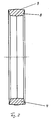
- a spacer ring 4 is shown in cross section in FIG. 2 of the drawing.
- the two end faces 8 of the spacer ring 4 are conical. This ensures that the adjacent spacer rings have small contact surfaces on which large surface pressures result when compressed. From this results the advantage that in the initial phase of compression by means of relatively small forces, a relatively large deformation can be achieved. With increasing deformation, the contact surfaces increase, so that finally a certain solidification of the knife shaft 1 is achieved after reaching the predetermined dimension. This means that the desired deformation of the spacer rings 4 is achieved without great effort during assembly, but that, on the other hand, the knife shaft 1 in the fully assembled state achieves sufficient stability which is adapted to the operating conditions.
- the degree of beveling of the end faces 8 of the spacer rings 4 and the selection of the material make it possible to adapt the spacer rings 4 to the conditions required in each case. It has proven to be useful to produce the spacer rings 4 from a suitable plastic for knife shafts 1 for small document shredders. For highly loaded knife shafts 1, it has proven to be expedient to produce the spacer rings 4 from a deformable metal.
- the selection of the right materials depends on the degree of stress on the spacer rings 4 and the design of the end faces 8 of the spacer rings 4. As has been shown, it is particularly advantageous if the end faces 8 are inclined at an angle of approximately 15 °.
- the spacer rings 4 are advantageously spherical on their peripheral surfaces 9. This ensures that the circumferential surfaces 9 bulging in the vicinity of the contact surfaces do not enlarge the outer diameter of the spacer rings 4 during the deformation in the region of the contact surfaces.
- the crowning of the peripheral surfaces 9 of the spacer rings 4 is preferably chosen so that the bulge of the peripheral surfaces 9 does not protrude beyond the largest diameter in the middle of the peripheral surfaces 9.
- spacer rings 4 are made of plastic, it is possible, for example, to inject the spacer rings 4 from polyethylene. Spacer rings 4 subjected to higher loads can also be made from brass alloys, for example. Alternatively, of course, the use of other deformable materials is also possible.
- the knife shaft 1 according to the invention is assembled in such a way that the knife disks 3 and the spacer rings 4 are pushed onto the shaft 2.
- the cutter disks 3 and the spacer rings 4 are pressed together by means of a device (not shown in the drawing) to such an extent that the second snap ring 6 can also be inserted into the groove 5 at the free end of the shaft 2 .
- the spacing of the grooves 5 specify the correct length dimension for the knife shaft 1.
- the snap rings 6 hold the knife disks 3 and the spacer rings 4 in a clamped state against one another.
- the correct dimension is obtained not only for the total length of the knife shaft 1, but also for the distance between the individual knife disks 3. It is therefore independent of fluctuations in the material thicknesses of the individual knife disks 3, a large dimensional accuracy the knife shaft 1 ensured.
- the knife disks 3 of the two knife shafts 1, which interlock when the document shredder is assembled are always at a correct distance from one another.
- the knife disks 3 lie against each other in such a way that a perfect cutting process is ensured, but on the other hand the frictional forces between the knife disks 3 are so low that the performance of the document shredder is not impaired.
- the knife shaft 1 according to the invention ensures that high-performance document shredders can be produced in a uniformly high quality with inexpensive production.
Landscapes
- Engineering & Computer Science (AREA)
- Food Science & Technology (AREA)
- Crushing And Pulverization Processes (AREA)
Claims (5)
- Arbre porte-lames (1) pour déchiqueteur de documents, constitué par des lames en forme de disques (3) et des bagues d'écartement (4) intermédiaires bloquées longitudinalement sur le corps de l'arbre (2) au moyen de blocage axial (5, 6), caractérisé en ce que les bagues d'écartement (4) de l'arbre porte-lames (1) ont au moins une de leurs faces frontales de forme conique et en ce que les intervalles entre les lames (3) sont amenés à une mesure prédéterminée par un dispositif de blocage (gorge 5, anneau élastique 6) par compression des bagues d'écartement dans la direction axiale.
- Arbre porte-lames (1) selon la revendication 1, caractérisé en ce que la plus grande largeur des bagues d'écartement (4), ayant au moins une face frontale (8) de forme conique, est située radialement à l'extérieur.
- Arbre porte-lames (1) selon l'une des revendications précédentes, caractérisé en ce que les bagues d'écartement (4) ont au moins une face frontale (8) de forme conique avec un angle d'environ 15°.
- Arbre porte-lames (1) selon une des revendications précédentes, caractérisé en ce que les bagues d'écartement (4) ont une surface périphérique (8) bombée.
- Arbre porte-lames (1) selon l'une des revendications précédentes, caractérisé en ce que les moyens de blocage axial des lames (3) et des bagues d'écartement (4) sont réalisés par des gorges (5) des côtés du corps de l'arbre (2) dans lesquelles s'insèrent des anneaux élastiques (6).
Applications Claiming Priority (2)
| Application Number | Priority Date | Filing Date | Title |
|---|---|---|---|
| DE4005556A DE4005556A1 (de) | 1990-02-22 | 1990-02-22 | Messerwelle fuer schriftgutvernichter |
| DE4005556 | 1990-02-22 |
Publications (2)
| Publication Number | Publication Date |
|---|---|
| EP0443337A1 EP0443337A1 (fr) | 1991-08-28 |
| EP0443337B1 true EP0443337B1 (fr) | 1993-11-10 |
Family
ID=6400710
Family Applications (1)
| Application Number | Title | Priority Date | Filing Date |
|---|---|---|---|
| EP91100862A Expired - Lifetime EP0443337B1 (fr) | 1990-02-22 | 1991-01-24 | Arbre porte-lames pour déchiqueteur de documents |
Country Status (4)
| Country | Link |
|---|---|
| US (1) | US5135178A (fr) |
| EP (1) | EP0443337B1 (fr) |
| JP (1) | JPH05123593A (fr) |
| DE (2) | DE4005556A1 (fr) |
Families Citing this family (20)
| Publication number | Priority date | Publication date | Assignee | Title |
|---|---|---|---|---|
| US5358187A (en) * | 1992-09-09 | 1994-10-25 | Ward Paula M L | Methods of and apparatus for producing improved bedding materials from scrap newspaper |
| US5799887A (en) * | 1996-10-24 | 1998-09-01 | Fellowes Mfg. Co. | Cutting cylinder for a document shredding machine |
| US5906569A (en) * | 1997-09-30 | 1999-05-25 | Ranpak Corp. | Conversion machine and method for making folded strips |
| DE10034719A1 (de) * | 2000-07-17 | 2002-01-31 | Josef Froehling Gmbh Walzwerks | Längsteilschere |
| US6742731B2 (en) | 2002-03-19 | 2004-06-01 | Inter-Source Recovery Systems | System and method of shredding wet chips in a flume |
| US7028935B2 (en) * | 2003-07-01 | 2006-04-18 | Inter-Source Recovery Systems, Inc. | Apparatus and method for shredding wet chip materials |
| US7467755B2 (en) * | 2003-07-01 | 2008-12-23 | Inter-Source Recovery Systems, Inc. | Parts separator apparatus and method of shredding |
| US7040559B2 (en) | 2004-04-02 | 2006-05-09 | Fellowes Inc. | Shredder with lock for on/off switch |
| US7380736B2 (en) * | 2005-05-04 | 2008-06-03 | Inter-Source Systems, Inc. | In-line shredder apparatus and method for shredding materials |
| US7641135B1 (en) * | 2006-02-28 | 2010-01-05 | Emily Lo | Combinative cutting wheel of a rotary cutter of paper shredder |
| CN2915259Y (zh) | 2006-07-14 | 2007-06-27 | 上海震旦办公设备有限公司 | 碎纸机触碰安全装置 |
| US8008812B2 (en) | 2006-07-14 | 2011-08-30 | Aurora Office Equipment Co., Ltd. | Paper shredder control system responsive to touch-sensitive element |
| US20080121340A1 (en) * | 2006-11-08 | 2008-05-29 | Meng-Chieh Lin | Foam imprinting method |
| US7637448B2 (en) | 2007-02-21 | 2009-12-29 | Fellowes, Inc. | Plastic center shredder disc |
| CN201239643Y (zh) | 2008-08-06 | 2009-05-20 | 上海震旦办公设备有限公司 | 不择纸的全自动碎纸机 |
| CN201244502Y (zh) | 2008-08-19 | 2009-05-27 | 上海震旦办公设备有限公司 | 自动碎纸机可剃钉结构 |
| CN101543800A (zh) | 2009-05-07 | 2009-09-30 | 上海震旦办公设备有限公司 | 碎纸机防卡纸保护装置 |
| US8723468B2 (en) | 2011-04-28 | 2014-05-13 | Aurora Office Equipment Co., Ltd. | Cooled motor |
| US8708260B2 (en) | 2011-08-08 | 2014-04-29 | Aurora Office Equipment Co., Ltd. | Depowered standby paper shredder and method |
| US9968944B2 (en) | 2013-03-15 | 2018-05-15 | Inter-Source Recovery Systems | Parts separator |
Family Cites Families (10)
| Publication number | Priority date | Publication date | Assignee | Title |
|---|---|---|---|---|
| US737194A (en) * | 1903-03-14 | 1903-08-25 | Thos Mills & Bro | Means for adjustably spacing disk cutters. |
| GB454623A (en) * | 1934-03-27 | 1936-09-28 | Eduard Quester | Improvements in or relating to cutting devices |
| US2589603A (en) * | 1949-04-26 | 1952-03-18 | Cohen Herman | Crushing machine |
| US2804134A (en) * | 1954-02-01 | 1957-08-27 | John G Berry | Sheet material slitting machine |
| GB1022409A (en) * | 1963-05-04 | 1966-03-16 | Auguste Paul Durand | Device for destroying documents |
| DE2524086C3 (de) * | 1975-05-30 | 1986-07-31 | Feinwerktechnik Schleicher & Co, 7778 Markdorf | Vorrichtung zum Zerreißen von blattförmigen Materials mit zwei Walzen |
| JPS55119451A (en) * | 1979-03-08 | 1980-09-13 | Hiroshi Yamashita | Device for cutting discarding document |
| DE3313231A1 (de) * | 1983-04-13 | 1984-10-18 | Geha-Werke Gmbh, 3000 Hannover | Schneidwerk fuer aktenvernichter |
| JPS59160545A (ja) * | 1984-02-15 | 1984-09-11 | 松下電器産業株式会社 | シユレツダ− |
| DE3616554C2 (de) * | 1986-05-16 | 1995-05-24 | Schleicher Co Feinwerktech | Messerwalzen-Abstreifvorrichtung für Aktenvernichter oder dgl. |
-
1990
- 1990-02-22 DE DE4005556A patent/DE4005556A1/de active Granted
-
1991
- 1991-01-24 DE DE91100862T patent/DE59100564D1/de not_active Expired - Fee Related
- 1991-01-24 EP EP91100862A patent/EP0443337B1/fr not_active Expired - Lifetime
- 1991-02-20 JP JP3026175A patent/JPH05123593A/ja active Pending
- 1991-02-22 US US07/658,852 patent/US5135178A/en not_active Expired - Fee Related
Also Published As
| Publication number | Publication date |
|---|---|
| US5135178A (en) | 1992-08-04 |
| DE59100564D1 (de) | 1993-12-16 |
| JPH05123593A (ja) | 1993-05-21 |
| DE4005556C2 (fr) | 1992-01-16 |
| DE4005556A1 (de) | 1991-08-29 |
| EP0443337A1 (fr) | 1991-08-28 |
Similar Documents
| Publication | Publication Date | Title |
|---|---|---|
| EP0443337A1 (fr) | Arbre porte-lames pour déchiqueteur de documents | |
| DE3828692C2 (fr) | ||
| AT414346B (de) | Sicherungselement zur sicherung von schraubenelementen | |
| DE2925058C2 (de) | Drehfeste Preßfüge-Verbindung zweier Bauteile zur Übertragung von Drehmomenten | |
| DE68920548T2 (de) | Zahnstangenlenkeinrichtung. | |
| EP2446166B1 (fr) | Rondelle ondulée et ensemble de support pour arbre | |
| DE19627288A1 (de) | Lager mit Nullspiel | |
| EP1999388B2 (fr) | Boîte de vitesses à rondelle de compensation | |
| EP2997286B1 (fr) | Vis d'entraînement à billes | |
| DE102021211446A1 (de) | Vorrichtung zum Andrücken einer Zahnstange an ein Ritzel | |
| EP1529587B1 (fr) | Alésoir de machine, tête d'outil et queue | |
| DE2729064A1 (de) | Symmetrische flache kraftmesszelle | |
| DE2901933C2 (fr) | ||
| WO2020148028A1 (fr) | Palier axial en feuille pour systèmes de piles à combustible | |
| DE10245269A1 (de) | Getriebe-Antriebseinheit mit geneigter Anschlagsfläche | |
| EP1961995A2 (fr) | Dispositif de transformation d'un mouvement rotatif en mouvement axial | |
| EP0412997B1 (fr) | Garniture d'etancheite | |
| DE2932248A1 (de) | Anordnung zum axialen fixieren und/oder anstellen von maschinenteilen | |
| DE3326593A1 (de) | Vorrichtung zur messung der spannungsverteilung ueber die breite von biegsamen baendern | |
| DE19953092B4 (de) | Lageranordnung | |
| CH681106A5 (fr) | ||
| DE2209678C3 (de) | Drehfeste Verbindung zweier einander umschließender Maschinenelemente, insbesondere einer Nabe mit einer WeUe | |
| DE1202588B (de) | Kugelkaefig eines Gleichlaufdrehgelenkes | |
| DE102019107607A1 (de) | Spannsystem, Verwendung einer Spannscheibe und Verfahren zum Vorspannen eines Befestigungselements | |
| DE3227862A1 (de) | Zerkleinerungsvorrichtung und verfahren zu deren herstellung |
Legal Events
| Date | Code | Title | Description |
|---|---|---|---|
| PUAI | Public reference made under article 153(3) epc to a published international application that has entered the european phase |
Free format text: ORIGINAL CODE: 0009012 |
|
| 17P | Request for examination filed |
Effective date: 19910124 |
|
| AK | Designated contracting states |
Kind code of ref document: A1 Designated state(s): DE FR GB IT |
|
| 17Q | First examination report despatched |
Effective date: 19920729 |
|
| RAP1 | Party data changed (applicant data changed or rights of an application transferred) |
Owner name: GEHA-WERKE GMBH |
|
| GRAA | (expected) grant |
Free format text: ORIGINAL CODE: 0009210 |
|
| AK | Designated contracting states |
Kind code of ref document: B1 Designated state(s): DE FR GB IT |
|
| REF | Corresponds to: |
Ref document number: 59100564 Country of ref document: DE Date of ref document: 19931216 |
|
| ET | Fr: translation filed | ||
| ITF | It: translation for a ep patent filed | ||
| GBT | Gb: translation of ep patent filed (gb section 77(6)(a)/1977) |
Effective date: 19940204 |
|
| PLBE | No opposition filed within time limit |
Free format text: ORIGINAL CODE: 0009261 |
|
| STAA | Information on the status of an ep patent application or granted ep patent |
Free format text: STATUS: NO OPPOSITION FILED WITHIN TIME LIMIT |
|
| 26N | No opposition filed | ||
| PGFP | Annual fee paid to national office [announced via postgrant information from national office to epo] |
Ref country code: GB Payment date: 19990105 Year of fee payment: 9 |
|
| PGFP | Annual fee paid to national office [announced via postgrant information from national office to epo] |
Ref country code: FR Payment date: 19990118 Year of fee payment: 9 |
|
| PGFP | Annual fee paid to national office [announced via postgrant information from national office to epo] |
Ref country code: DE Payment date: 19990126 Year of fee payment: 9 |
|
| PG25 | Lapsed in a contracting state [announced via postgrant information from national office to epo] |
Ref country code: GB Free format text: LAPSE BECAUSE OF NON-PAYMENT OF DUE FEES Effective date: 20000124 |
|
| PG25 | Lapsed in a contracting state [announced via postgrant information from national office to epo] |
Ref country code: DE Free format text: LAPSE BECAUSE OF NON-PAYMENT OF DUE FEES Effective date: 20000131 |
|
| GBPC | Gb: european patent ceased through non-payment of renewal fee |
Effective date: 20000124 |
|
| PG25 | Lapsed in a contracting state [announced via postgrant information from national office to epo] |
Ref country code: FR Free format text: LAPSE BECAUSE OF NON-PAYMENT OF DUE FEES Effective date: 20000929 |
|
| REG | Reference to a national code |
Ref country code: FR Ref legal event code: ST |
|
| PG25 | Lapsed in a contracting state [announced via postgrant information from national office to epo] |
Ref country code: IT Free format text: LAPSE BECAUSE OF NON-PAYMENT OF DUE FEES;WARNING: LAPSES OF ITALIAN PATENTS WITH EFFECTIVE DATE BEFORE 2007 MAY HAVE OCCURRED AT ANY TIME BEFORE 2007. THE CORRECT EFFECTIVE DATE MAY BE DIFFERENT FROM THE ONE RECORDED. Effective date: 20050124 |