EP0442794B1 - Dispositif de réchauffage de deux fractions de gaz en échange de chaleur avec des fumées - Google Patents
Dispositif de réchauffage de deux fractions de gaz en échange de chaleur avec des fumées Download PDFInfo
- Publication number
- EP0442794B1 EP0442794B1 EP91400332A EP91400332A EP0442794B1 EP 0442794 B1 EP0442794 B1 EP 0442794B1 EP 91400332 A EP91400332 A EP 91400332A EP 91400332 A EP91400332 A EP 91400332A EP 0442794 B1 EP0442794 B1 EP 0442794B1
- Authority
- EP
- European Patent Office
- Prior art keywords
- fraction
- gas
- air
- gas fraction
- fumes
- Prior art date
- Legal status (The legal status is an assumption and is not a legal conclusion. Google has not performed a legal analysis and makes no representation as to the accuracy of the status listed.)
- Expired - Lifetime
Links
- 239000007789 gas Substances 0.000 title claims description 20
- 238000010438 heat treatment Methods 0.000 title claims description 3
- 239000003517 fume Substances 0.000 title description 8
- 239000000779 smoke Substances 0.000 claims description 8
- 239000000446 fuel Substances 0.000 claims description 3
- 238000002485 combustion reaction Methods 0.000 description 7
- 239000003245 coal Substances 0.000 description 2
- 238000005243 fluidization Methods 0.000 description 2
- 238000003303 reheating Methods 0.000 description 2
- 230000005540 biological transmission Effects 0.000 description 1
- 239000003546 flue gas Substances 0.000 description 1
- 239000012530 fluid Substances 0.000 description 1
- 239000002803 fossil fuel Substances 0.000 description 1
- 239000000463 material Substances 0.000 description 1
Images
Classifications
-
- F—MECHANICAL ENGINEERING; LIGHTING; HEATING; WEAPONS; BLASTING
- F23—COMBUSTION APPARATUS; COMBUSTION PROCESSES
- F23L—SUPPLYING AIR OR NON-COMBUSTIBLE LIQUIDS OR GASES TO COMBUSTION APPARATUS IN GENERAL ; VALVES OR DAMPERS SPECIALLY ADAPTED FOR CONTROLLING AIR SUPPLY OR DRAUGHT IN COMBUSTION APPARATUS; INDUCING DRAUGHT IN COMBUSTION APPARATUS; TOPS FOR CHIMNEYS OR VENTILATING SHAFTS; TERMINALS FOR FLUES
- F23L15/00—Heating of air supplied for combustion
- F23L15/04—Arrangements of recuperators
-
- Y—GENERAL TAGGING OF NEW TECHNOLOGICAL DEVELOPMENTS; GENERAL TAGGING OF CROSS-SECTIONAL TECHNOLOGIES SPANNING OVER SEVERAL SECTIONS OF THE IPC; TECHNICAL SUBJECTS COVERED BY FORMER USPC CROSS-REFERENCE ART COLLECTIONS [XRACs] AND DIGESTS
- Y02—TECHNOLOGIES OR APPLICATIONS FOR MITIGATION OR ADAPTATION AGAINST CLIMATE CHANGE
- Y02E—REDUCTION OF GREENHOUSE GAS [GHG] EMISSIONS, RELATED TO ENERGY GENERATION, TRANSMISSION OR DISTRIBUTION
- Y02E20/00—Combustion technologies with mitigation potential
- Y02E20/34—Indirect CO2mitigation, i.e. by acting on non CO2directly related matters of the process, e.g. pre-heating or heat recovery
Definitions
- the present invention relates to a device for reheating two gas fractions, different or under different pressures, in exchange for heat with fumes resulting from the combustion of a fuel, in particular in a fluidized bed, comprising tubular bundles traversed by the fumes and around which circulates a first fraction of gas to be heated, inside a box surrounded by an enclosure in which circulates a second fraction of gas.
- the object of the present invention is to provide a device for reheating two gas fractions, different or under different pressures, which comprises only a single tube bundle traversed by the fumes, and is therefore less costly than a device with two tube bundle heat exchangers in parallel, while not involving losses on the gas fractions to be heated and without requiring adjustments to the smoke intake.
- the device according to the invention is characterized in that it further comprises heat pipes provided with fins arranged between the path of this first fraction of gas and that of the second fraction of gas.
- the path of the first fraction of gas comprises passages with crcized currents relative to the tubes in which the flue gases circulate, and intermediate passages external to these tubes, in which the ends of the heat pipes are arranged in exchange for heat with the second fraction of gas.
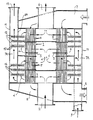
- the exchange device comprises a tubular bundle 1, composed of tubes 5 inside which circulate combustion fumes admitted at 7 and evacuated at 8.
- a fraction of combustion air intended to be admitted into a fireplace, by example below the intake of divided coal in the case of the primary air circuit of a fluidized bed combustion reactor, is introduced in 2 into a box 8A surrounding the tube bundle 1 and evacuated heated in 6.
- the path of this fraction includes cross-current passages with respect to the tubes 5, represented by arrows 3, and passages parallel to the tubes, outside of these, represented by arrows 4.
- a second fraction of air intended for example to ensure the fluidization of a material used in a fluidized bed exchanger, admitted at 9, passes into an annular enclosure 7A surrounding the box 8A, and to the inside of an external shroud 11.
- Heat pipes 12 provided with fins 10 which are very close together because operating on air extend transversely to the passages 4 of the first fraction of air parallel to the tubes, and to the enclosure 7, by crossing the wall of the internal box 8. They thus ensure the transmission to the second fraction of air of part of the heat given off by the fumes to the first fraction of air in the cross-current passages 3.
- This fraction d air is evacuated in 13.
- the heat supplied by the fumes is thus transmitted on the one hand to the first fraction of air and on the other hand to the second fraction of air via the first fraction of air.
- the exchange between smoke and first fraction of air is optimal since the temperature of the first fraction of air is lowered at its exit under the effect of the exchange with the second fraction of air.
- the first fraction of air passes from 40 ° C to 220 ° C towards its outlet 6 while the second fraction of air did not exist the temperature of the first fraction of air would rise to 270 ° C which would make heat exchange very difficult which depends on the difference between the two temperatures of the fluids in exchange .
Landscapes
- Engineering & Computer Science (AREA)
- Chemical & Material Sciences (AREA)
- Combustion & Propulsion (AREA)
- Mechanical Engineering (AREA)
- General Engineering & Computer Science (AREA)
- Heat-Exchange Devices With Radiators And Conduit Assemblies (AREA)
- Devices And Processes Conducted In The Presence Of Fluids And Solid Particles (AREA)
Description
- La présente invention concerne un dispositif de réchauffage de deux fractions de gaz, différentes ou sous des pressions différentes, en échange de chaleur avec des fumées résultant de la combustion d'un combustible, notamment en lit fluidisé, comprenant des faisceaux tubulaires parcourus par les fumées et autour desquels circule une première fraction de gaz à réchauffer, à l'intérieur d'un caisson entouré par une enceinte dans laquelle circule une seconde fraction de gaz.
- Lorsque l'on veut réchauffer en échange de chaleur avec des fumées deux fractions de gaz différentes ou sous des pressions différentes, par exemple une fraction primaire d'air de fluidisation d'un combustible divisé et une fraction secondaire d'air de combustion, on est généralement amené à disposer en parallèle deux échangeurs à faisceaux tubulaires comme dans le dispositif décrit dans le document EP-A-246486. Ceci entraîne une complication d'appareillage et des coûts importants. De plus il faut régler les admissions de fumées dans les deux échangeurs pour éviter une différence trop importante dans les températures de sortie des fumées.
- La présente invention a pour but de procurer un dispositif de réchauffage de deux fractions de gaz, différentes ou sous des pressions différentes, qui ne comporte qu'un seul faisceau tubulaire parcouru par les fumées, et soit donc d'un coût moindre qu'un dispositif à deux échangeurs à faisceau tubulaire en parallèle, tout en n'impliquant pas de pertes sur les fractions de gaz à réchauffer et en ne nécessitant pas des réglages d'admissions des fumées.
- Le dispositif selon l'invention est caractérisé en ce qu'il comporte en outre des caloducs munis d'ailettes disposés entre le trajet de cette première fraction de gaz et celui de la seconde fraction de gaz.
- De préférence, le trajet de la première fraction de gaz comporte des passages à courants crcisés par rapport aux tubes dans lesquels circulent les fumées, et des passages intermédiaires externes à ces tubes, dans lesquels sont disposés les extrémités des caloducs en échange de chaleur avec la seconde fraction de gaz.
- Il est décrit ci-après, à titre d'exemple et en référence à la figure unique du dessin annexé, un dispositif de réchauffage d'une fraction d'air de fluidisation et d'une fraction d'air de combustion pour réacteur de combustion à lit fluidisé circulant de charbon ou autre combustible fossile divisé.
- Le dispositif d'échange comprend un faisceau tubulaire 1, composé de tubes 5 à l'intérieur desquels circulent des fumées de combustion admises en 7 et évacuées en 8. Une fraction d'air de combustion, destinée à être admise dans un foyer, par exemple au-dessous de l'admission du charbon divisé dans le cas du circuit d'air primaire d'un réacteur de combustion à lit fluidisé, est introduite en 2 dans un caisson 8A entourant le faisceau tubulaire 1 et évacuée réchauffée en 6. Le trajet de cette fraction comporte des passages à courants croisés par rapport aux tubes 5, représentés par des flèches 3, et des passages parallèles aux tubes, à l'extérieur de ceux-ci, représentés par les flèches 4.
- Par ailleurs, une seconde fraction d'air, destinée par exemple à assurer la fluidisation d'un matériau mis en oeuvre dans un échangeur à lit fluidisé, admise en 9, passe dans une enceinte annulaire 7A entourant le caisson 8A, et à l'intérieur d'une virole externe 11. Des caloducs 12 munis d'ailettes 10 très rapprochées car opérant sur de l'air s'étendent transversalement aux passages 4 de la première fraction d'air parallèles aux tubes, et à l'enceinte 7, en traversant la paroi du caisson interne 8. Ils assurent ainsi la transmission à la seconde fraction d'air d'une partie de la chaleur cédée par les fumées à la première fraction d'air dans les passages à courants croisés 3. Cette fraction d'air est évacuée en 13.
- La chaleur amenée par les fumées est ainsi transmise d'une part à la première fraction d'air et d'autre part à la seconde fraction d'air par l'intermédiaire de la première fraction d'air. L'échange entre fumées et première fraction d'air est optimale puisque la température de la première fraction d'air se trouve baissée à sa sortie sous l'effet de l'échange avec la seconde fraction d'air.
- Ainsi par exemple pour des fumées à 300°C à l'entrée la première fraction d'air passe de 40°C à 220°C vers sa sortie 6 alors que s'il n'existait pas la seconde fraction d'air la température de la première fraction d'air monterait jusqu'à 270°C ce qui rendrait très difficile l'échange de chaleur qui dépend de l'écart entre les deux températures des fluides en échange.
Claims (2)
- Dispositif de réchauffage de deux fractions de gaz, différentes ou sous des pressions différentes, en échange de chaleur avec des fumées résultant de la combustion d'un combustible, notamment en lit fluidisé, comprenant des faisceaux tubulaires (1) parcourus par les fumées et autour desquels circule une première fraction de gaz à réchauffer à l'intérieur d'un caisson (8A), entouré par une enceinte (11) dans laquelle circule une seconde fraction de gaz à réchauffer, caractérisé en ce qu'il comporte en outre des caloducs (12) munis d'ailettes (10) disposés entre le trajet de la première fraction de gaz et celui de la seconde fraction de gaz.
- Dispositif selon la revendication 1, caractérisé en ce que le trajet de la première fraction de gaz comporte des passages (3) à courants croisés par rapport aux tubes dans lesquels circulent les fumées, et des passages intermédiaires (4) externes à ces tubes, dans lesquels sont disposés les extrémités des caloducs (12) en échange de chaleur avec la première fraction de gaz.
Applications Claiming Priority (2)
| Application Number | Priority Date | Filing Date | Title |
|---|---|---|---|
| FR9001685 | 1990-02-13 | ||
| FR9001685A FR2658279B1 (fr) | 1990-02-13 | 1990-02-13 | Dispositif de rechauffage de deux fractions de gaz en echange de chaleur avec des fumees. |
Publications (2)
| Publication Number | Publication Date |
|---|---|
| EP0442794A1 EP0442794A1 (fr) | 1991-08-21 |
| EP0442794B1 true EP0442794B1 (fr) | 1993-10-27 |
Family
ID=9393655
Family Applications (1)
| Application Number | Title | Priority Date | Filing Date |
|---|---|---|---|
| EP91400332A Expired - Lifetime EP0442794B1 (fr) | 1990-02-13 | 1991-02-12 | Dispositif de réchauffage de deux fractions de gaz en échange de chaleur avec des fumées |
Country Status (5)
| Country | Link |
|---|---|
| EP (1) | EP0442794B1 (fr) |
| DE (1) | DE69100545T2 (fr) |
| DK (1) | DK0442794T3 (fr) |
| ES (1) | ES2046860T3 (fr) |
| FR (1) | FR2658279B1 (fr) |
Families Citing this family (1)
| Publication number | Priority date | Publication date | Assignee | Title |
|---|---|---|---|---|
| FI20095566A7 (fi) * | 2009-05-22 | 2010-11-23 | Metso Power Oy | Kattilan palamisilman esilämmityslaitteisto ja voimalaitos |
Family Cites Families (4)
| Publication number | Priority date | Publication date | Assignee | Title |
|---|---|---|---|---|
| US4416325A (en) * | 1980-03-31 | 1983-11-22 | Foster Wheeler Energy Corporation | Heat exchanger |
| GB2104206B (en) * | 1981-08-19 | 1985-01-09 | Foster Wheeler Power Prod | Air heater |
| FR2583144B1 (fr) * | 1985-06-10 | 1989-05-12 | Sofresid | Perfectionnements apportes aux bruleurs autorecuperateurs |
| FR2598496B1 (fr) * | 1986-05-06 | 1990-01-05 | Stein Industrie | Echangeur de rechauffage d'air sous pression en contre-courant de fumees circulant dans des faisceaux tubulaires |
-
1990
- 1990-02-13 FR FR9001685A patent/FR2658279B1/fr not_active Expired - Fee Related
-
1991
- 1991-02-12 ES ES199191400332T patent/ES2046860T3/es not_active Expired - Lifetime
- 1991-02-12 EP EP91400332A patent/EP0442794B1/fr not_active Expired - Lifetime
- 1991-02-12 DE DE91400332T patent/DE69100545T2/de not_active Expired - Fee Related
- 1991-02-12 DK DK91400332.2T patent/DK0442794T3/da active
Also Published As
| Publication number | Publication date |
|---|---|
| DK0442794T3 (da) | 1994-02-21 |
| FR2658279A1 (fr) | 1991-08-16 |
| ES2046860T3 (es) | 1994-02-01 |
| DE69100545D1 (de) | 1993-12-02 |
| EP0442794A1 (fr) | 1991-08-21 |
| FR2658279B1 (fr) | 1992-04-24 |
| DE69100545T2 (de) | 1994-02-17 |
Similar Documents
| Publication | Publication Date | Title |
|---|---|---|
| JP3017106B2 (ja) | 外部燃焼型動力装置に熱を供給する方法及び装置 | |
| US4164210A (en) | Pulse combustion system for heating of air | |
| JP3188270B2 (ja) | 蒸気発生器 | |
| EP0442794B1 (fr) | Dispositif de réchauffage de deux fractions de gaz en échange de chaleur avec des fumées | |
| US6810836B1 (en) | Finned tube water heater | |
| RU2168121C1 (ru) | Технологический нагреватель | |
| US4180019A (en) | Process heater | |
| JP3190939B2 (ja) | 蒸気発生装置 | |
| JPS609203B2 (ja) | 過給ボイラの構造 | |
| ES2156689A1 (es) | Generador de agua caliente para funcionamiento a baja temperatura. | |
| JPH03502237A (ja) | 流体流を加熱する方法及び装置 | |
| EP0499760B1 (fr) | Chaudière et installation de chauffage central et/ou de production d'eau chaude sanitaire | |
| RU2042878C1 (ru) | Горизонтальный отопительный котел | |
| US4171693A (en) | Furnace | |
| FR2694382A1 (fr) | Chaudière à basse température à panneaux radiants catalytiques. | |
| JPS60142106A (ja) | 蒸気発生装置 | |
| RU2090800C1 (ru) | Горелка для твердого топлива с факельной трубкой | |
| CN210602777U (zh) | 一种加热炉 | |
| JPH09243019A (ja) | 循環式流動層ボイラ装置 | |
| CA2159124C (fr) | Chaudiere verticale sous tubes d'eau | |
| JPH06307601A (ja) | ボイラ火炉水冷壁 | |
| JP3348894B2 (ja) | ガスクーラにおけるトランスファーダクトと炉壁との接続構造 | |
| KR940006238Y1 (ko) | 가스보일러의 난방, 온수 겸용 듀얼타입 히트 트랜스퍼 모듈 | |
| JPH07139701A (ja) | 環状貫流ボイラ | |
| RU1787238C (ru) | Способ работы экранированной топки котельного агрегата и топка котельного агрегата |
Legal Events
| Date | Code | Title | Description |
|---|---|---|---|
| PUAI | Public reference made under article 153(3) epc to a published international application that has entered the european phase |
Free format text: ORIGINAL CODE: 0009012 |
|
| AK | Designated contracting states |
Kind code of ref document: A1 Designated state(s): BE CH DE DK ES FR GB IT LI SE |
|
| 17P | Request for examination filed |
Effective date: 19920217 |
|
| 17Q | First examination report despatched |
Effective date: 19920624 |
|
| GRAA | (expected) grant |
Free format text: ORIGINAL CODE: 0009210 |
|
| AK | Designated contracting states |
Kind code of ref document: B1 Designated state(s): BE CH DE DK ES FR GB IT LI SE |
|
| GBT | Gb: translation of ep patent filed (gb section 77(6)(a)/1977) |
Effective date: 19931103 |
|
| REF | Corresponds to: |
Ref document number: 69100545 Country of ref document: DE Date of ref document: 19931202 |
|
| ITF | It: translation for a ep patent filed | ||
| REG | Reference to a national code |
Ref country code: ES Ref legal event code: FG2A Ref document number: 2046860 Country of ref document: ES Kind code of ref document: T3 |
|
| REG | Reference to a national code |
Ref country code: DK Ref legal event code: T3 |
|
| PLBE | No opposition filed within time limit |
Free format text: ORIGINAL CODE: 0009261 |
|
| STAA | Information on the status of an ep patent application or granted ep patent |
Free format text: STATUS: NO OPPOSITION FILED WITHIN TIME LIMIT |
|
| 26N | No opposition filed | ||
| EAL | Se: european patent in force in sweden |
Ref document number: 91400332.2 |
|
| PGFP | Annual fee paid to national office [announced via postgrant information from national office to epo] |
Ref country code: GB Payment date: 19990115 Year of fee payment: 9 |
|
| PGFP | Annual fee paid to national office [announced via postgrant information from national office to epo] |
Ref country code: DE Payment date: 19990122 Year of fee payment: 9 |
|
| PGFP | Annual fee paid to national office [announced via postgrant information from national office to epo] |
Ref country code: SE Payment date: 19990125 Year of fee payment: 9 Ref country code: DK Payment date: 19990125 Year of fee payment: 9 |
|
| PGFP | Annual fee paid to national office [announced via postgrant information from national office to epo] |
Ref country code: CH Payment date: 19990201 Year of fee payment: 9 |
|
| PG25 | Lapsed in a contracting state [announced via postgrant information from national office to epo] |
Ref country code: GB Free format text: LAPSE BECAUSE OF NON-PAYMENT OF DUE FEES Effective date: 20000212 Ref country code: DK Free format text: LAPSE BECAUSE OF NON-PAYMENT OF DUE FEES Effective date: 20000212 |
|
| PG25 | Lapsed in a contracting state [announced via postgrant information from national office to epo] |
Ref country code: SE Free format text: LAPSE BECAUSE OF NON-PAYMENT OF DUE FEES Effective date: 20000213 |
|
| PG25 | Lapsed in a contracting state [announced via postgrant information from national office to epo] |
Ref country code: LI Free format text: LAPSE BECAUSE OF NON-PAYMENT OF DUE FEES Effective date: 20000229 Ref country code: CH Free format text: LAPSE BECAUSE OF NON-PAYMENT OF DUE FEES Effective date: 20000229 |
|
| GBPC | Gb: european patent ceased through non-payment of renewal fee |
Effective date: 20000212 |
|
| EUG | Se: european patent has lapsed |
Ref document number: 91400332.2 |
|
| REG | Reference to a national code |
Ref country code: CH Ref legal event code: PL |
|
| REG | Reference to a national code |
Ref country code: DK Ref legal event code: EBP |
|
| PG25 | Lapsed in a contracting state [announced via postgrant information from national office to epo] |
Ref country code: DE Free format text: LAPSE BECAUSE OF NON-PAYMENT OF DUE FEES Effective date: 20001201 |
|
| PGFP | Annual fee paid to national office [announced via postgrant information from national office to epo] |
Ref country code: BE Payment date: 20010213 Year of fee payment: 11 |
|
| PGFP | Annual fee paid to national office [announced via postgrant information from national office to epo] |
Ref country code: ES Payment date: 20020214 Year of fee payment: 12 |
|
| PG25 | Lapsed in a contracting state [announced via postgrant information from national office to epo] |
Ref country code: BE Free format text: LAPSE BECAUSE OF NON-PAYMENT OF DUE FEES Effective date: 20020228 |
|
| BERE | Be: lapsed |
Owner name: STEIN INDUSTRIE Effective date: 20020228 |
|
| PG25 | Lapsed in a contracting state [announced via postgrant information from national office to epo] |
Ref country code: ES Free format text: LAPSE BECAUSE OF NON-PAYMENT OF DUE FEES Effective date: 20030213 |
|
| PGFP | Annual fee paid to national office [announced via postgrant information from national office to epo] |
Ref country code: FR Payment date: 20040209 Year of fee payment: 14 |
|
| REG | Reference to a national code |
Ref country code: ES Ref legal event code: FD2A Effective date: 20030213 |
|
| PG25 | Lapsed in a contracting state [announced via postgrant information from national office to epo] |
Ref country code: IT Free format text: LAPSE BECAUSE OF NON-PAYMENT OF DUE FEES;WARNING: LAPSES OF ITALIAN PATENTS WITH EFFECTIVE DATE BEFORE 2007 MAY HAVE OCCURRED AT ANY TIME BEFORE 2007. THE CORRECT EFFECTIVE DATE MAY BE DIFFERENT FROM THE ONE RECORDED. Effective date: 20050212 |
|
| PG25 | Lapsed in a contracting state [announced via postgrant information from national office to epo] |
Ref country code: FR Free format text: LAPSE BECAUSE OF NON-PAYMENT OF DUE FEES Effective date: 20051031 |
|
| REG | Reference to a national code |
Ref country code: FR Ref legal event code: ST Effective date: 20051031 |