EP0442687A2 - Vorrichtung zur Detektierung von Fehlzündungen - Google Patents
Vorrichtung zur Detektierung von Fehlzündungen Download PDFInfo
- Publication number
- EP0442687A2 EP0442687A2 EP91301094A EP91301094A EP0442687A2 EP 0442687 A2 EP0442687 A2 EP 0442687A2 EP 91301094 A EP91301094 A EP 91301094A EP 91301094 A EP91301094 A EP 91301094A EP 0442687 A2 EP0442687 A2 EP 0442687A2
- Authority
- EP
- European Patent Office
- Prior art keywords
- measurements
- engine
- measurement
- cylinder
- variations
- Prior art date
- Legal status (The legal status is an assumption and is not a legal conclusion. Google has not performed a legal analysis and makes no representation as to the accuracy of the status listed.)
- Granted
Links
Images


Classifications
-
- G—PHYSICS
- G01—MEASURING; TESTING
- G01M—TESTING STATIC OR DYNAMIC BALANCE OF MACHINES OR STRUCTURES; TESTING OF STRUCTURES OR APPARATUS, NOT OTHERWISE PROVIDED FOR
- G01M15/00—Testing of engines
- G01M15/04—Testing internal-combustion engines
- G01M15/11—Testing internal-combustion engines by detecting misfire
Definitions
- the present invention relates to a method of and an apparatus for detecting misfire in an internal combustion engine.
- Misfire detection can be based on variations in engine output speed and, in a known arrangement, this is determined by means of a variable reluctance transducer or the like co-operating with a toothed wheel mounted on the output shaft.
- a timer arrangement determines the time taken for consecutive teeth to pass the transducer and this time period, or its reciprocal representing speed, is used to detect variations in engine speed.
- the teeth of the toothed wheel are machined to certain tolerances and the resulting variations in time of passage of consecutive teeth can result in spurious detection of speed variations which create errors in detecting misfire.
- Some internal combustion engines create cyclical rotary vibrations in their crank shaft which again affect the measurement of time periods between passage of consecutive teeth past the transducer. Such vibrations can occur at multiplies of half the firing frequency of the engine and again can lead to erroneous detection of misfire.
- the output speed of internal combustions for driving vehicles is not, of course, constant, but varies with the speed of the vehicle. Also, movement of a vehicle over rough and uneven surfaces can feed back speed variations to the engine output shaft. Thus, the engine output shaft is subjected to linear accelerations and decelerations and varying changes in speed during normal driving of the vehicle and this can lead to erroneous detection of misfire.
- an apparatus for detecting misfire in an internal combustion engine comprising means for making measurements representing engine speeds between the same points of cylinder and piston cycles of the engine, means for determining variations as the differences between measurements, and a comparator for comparing the variations with a threshold level and for signalling a misfire when the threshold level is exceeded.
- a method of detecting misfire in an internal combustion engine comprising the steps of making measurements representing engine speeds between the same points of cylinder and piston cycles of the engine, determining variations as the differences between measurements, comparing the variations with a threshold level, and signalling a misfire when the threshold level is exceeded.
- engine misfire can be detected on the basis of measurements representing engine speeds in a simple way and with a high degree of reliability.
- speed variations caused by the inertia and geometry of the moving parts of an engine do not mask any engine speed variations caused by a misfire.
- engine speed variations caused by the inertia and geometry are substantially the same at the same points in different piston and cylinder cycles and are thus removed or their effects greatly reduced in the process of determining the engine speed variations, for instance by forming the differences between consecutive pairs of engine speed measurements.
- misfire is detected on the basis of engine speed measurements, as opposed to period measurements (e.g. by taking the reciprocal of period measurements). It has been found that misfires can be detected throughout the whole range of engine speeds using threshold values which are constant or change little with engine speed.
- the threshold level may be a fixed threshold. In one experiment with a typical six cylinder four-stroke cycle engine, a fixed threshold corresponding to a speed variation of 15 RPM has proved satisfactory. It is thus possible to use a fixed speed variation threshold throughout the full range of engine speeds, thus simplifying the processing required to detect misfires.
- the same reference points are used for each engine speed measurement at the series of sampling points. This avoids any variation in measured engine speed caused by variation in the relative positions of the reference points.
- a toothed wheel on an engine crankshaft co-operating with a sensor, such as a variable reluctance transducer to detect the passage of the teeth. Tolerances in the width and spacing of the teeth give rise to variations in the measured engine speed.
- a compensating technique may be used whereby the average differences between period measurements for consecutive cylinders are used to establish correction factors which are applied to the instantaneous measurements.
- a first embodiment of the invention provides an apparatus for detecting misfire in a multi-cylinder internal combustion engine, comprising: means for measuring the periods or speeds between first points and second points of cylinder and piston cycles of the engine; comparing means for comparing the xth, (x+1)th, (x+a)th, and (x+a+1)th periods or speeds to produce a comparison value, where a is the number of combustion events per period of a systematic measurement fluctuation or a multiple thereof and the xth and (x+a)th periods or speeds are of opposite polarity or sign and the (x+1)th and (x+a+1)th periods or speeds are of opposite polarity or sign in the comparison; and a comparator for comparing the comparison value with a threshold value to detect the occurrence of a misfire.
- the parameter a may, for instance, be made equal to the number of combustion events per revolution of an output shaft of the engine or a multiple thereof.
- systematic errors resulting, for instance, from a timing or measuring device driven by the output shaft can be reduced or eliminated.
- the comparison means may form the comparison value as T(x)-T(x+1)-T(x+a)+T(x+a+1), where T(i) is the ith period or speed.
- the measuring means may comprise a variable reluctance transducer co-operating with a toothed wheel driven by the engine output shaft.
- the threshold value may be a fixed value or may vary, for instance as a function of engine speed and engine load.
- a second embodiment of the invention provides a method of detecting misfire in a multi-cylinder internal combustion engine, comprising measuring the speeds or periods between first points and second points of cylinder and piston cycles of the engine; comparing the xth, (x+1)th, (x+a)th, and (x+a+1)th periods or speeds to produce a comparison value, where a is the number of combustion events per period of a systematic measurement fluctuation or a multiple thereof and the xth and (x+a)th periods or speeds are of opposite polarity or sign and the (x+1)th and (x+a+1)th periods or speeds are of opposite polarity or sign in the comparison; and comparing the comparison value with a threshold value to detect the occurrence of a misfire.
- the method may be performed for each cylinder and piston of a multi-cylinder engine by making speed measurements between respective series of the same cycle points for each cylinder and piston. For instance, engine speed may be measured between the same point in the cycle of each of the cylinders and pistons, for instance at or after top dead centre of the firing stroke for each piston, with the speed variations being determined for each series of points corresponding to each cylinder and piston.
- This not only allows misfire to be detected for each cylinder and piston but also allows identification of a misfiring cylinder and piston to be indicated. It is therefore possible to provide diagnostic information which may be used: by an engine management system in order to take corrective action; to warn a vehicle driver of a possible fault; and to assist service personnel in identifying and rectifying a fault.
- a history of engine misfires may be stored, for instance to facilitate subsequent evaluation by service personnel in order to diagnose faults in the engine.
- the method may be performed by and the apparatus embodied as a digital system, for instance a micro-controller including a programmed microprocessor, and may be provided as part of an engine management system.
- a crankshaft position/speed sensor may be connected via an interface circuit to a timer input terminal of a micro-controller.
- a third embodiment of the invention provides an apparatus for detecting misfire in an n cylinder internal combustion engine, where n is greater than 1, the apparatus comprising: means for measuring the periods or speeds between first points and second points of cylinder and piston cycles of the engine; calculating means for forming a time or speed value T as the difference between sums (T(x)+T(x+n-1)) and (T(y)+T(z)), where T(x) is the xth one of the periods or speeds, T(x+n-1) is the (x+n-1)th one of the periods or speeds, and T(y) and T(z) are periods or speeds between the xth and (x+n-1)th one of the periods or speeds; and a comparator for comparing the time or speed value T with a threshold level to detect the occurrence of misfire.
- This technique can be used with engines having even numbers of cylinders. It is believed that the technique can be used with engines having odd numbers of cylinders.
- the periods or speeds T(y) and T(z) are preferably mid-way between the xth and (x+n-1)th periods or speeds.
- the periods or speeds T(y) and T(z) are preferably the (x+(n/2)-1)th and (x+(n/2))th periods or speeds.
- the period or speed T(y) may be the (x+((n-1)/2))th period or speed and the period or speed T(z) may be the (x+((n-1)/2)-1)th period or speed, the (x+((n-1)/2))th period or speed, or the (x+((n-1)/2)+1)th period or speed i.e. the preceding, same, or succeeding period or speed.
- a fourth embodiment of the invention provides an apparatus for detecting misfire in an n cylinder internal combustion engine, where n is greater than 1, the apparatus comprising means for measuring the periods or speeds between first points and second points of cylinder and piston cycles of the engine; comparing means for comparing periods or speeds to form a comparison value in accordance with at least two of the following constraints:
- the apparatus may be used with a toothed wheel and transducer, such as a variable reluctance transducer, as the period or speed measuring means, any other suitable means may be provided, and tolerances in manufacture of such means are likewise compensated for.
- first and second points of each cylinder and piston cycle of the engine may be located at or near top dead centre of the piston between its compression and ignition strokes. In general, the first and second points will occur after this top dead centre position during the ignition stroke of the piston.
- the threshold level used by the comparator may be a fixed threshold level.
- the threshold level may vary with engine parameters, such as engine speed and load demand.
- a fifth embodiment of the invention provides a method of detecting misfire in an n cylinder internal combustion engine, where n is greater than 1, the method comprising measuring the periods or speeds between first points and second points of cylinder and piston cycles of the engine; calculating a time or speed value T as the difference between sums (T(x)+T(x+n-1)) and (T(y)+T(z)), where T(x) is the xth one of the periods or speeds, T(x+N-1) is the (x+n-1)th one of the periods or speeds, and T(y) and T(z) are periods or speeds between the xth and (x+n-1)th one of the periods or speeds; and comparing the time value T with a threshold level to detect the occurrence of misfire.
- a sixth embodiment of the invention provides a method of detecting misfire in an n cylinder internal combustion engine, where n is greater than 1, the method comprising measuring the periods or speeds between first points and second points of cylinder and piston cycles of the engine; comparing periods to form a comparison value in accordance with at least two of the following constraints:
- a seventh embodiment of the invention provides an apparatus for identifying a misfiring cylinder of a multi-cylinder internal combustion engine, comprising means for detecting pairs of misfires corresponding to at least two consecutive engine combustion events, and means for identifying the cylinder in which the first of the consecutive combustion events took place.
- An eighth embodiment of the invention provides a method of identifying a misfiring cylinder of a multi-cylinder internal combustion engine, comprising detecting misfires corresponding to at least two consecutive engine combustion events, and identifying the cylinder in which the first of the consecutive combustion events took place.
- the detection of misfires may be provided by apparatuses and methods according to the third to sixth embodiments of the invention, or by any other suitable means for detecting misfire.
- misfire of a single combustion event tends to cause a fluctuation in engine speed such that consecutive misfires are detected corresponding to an actual single misfire.
- each succeeding misfire is a "phantom" and misfiring actually took place during the first combustion event which gave rise to misfire detection.
- a single misfire can give rise to pairs, triplets, or larger groups of consecutive misfire detections depending, for instance, on the type of misfire detection being used. This can be ascertained by testing.
- misfire detections In the case where a single misfire causes a pair of consecutive detections, should two consecutive misfires actually occur, three consecutive misfire events are generally detected so that, by dealing with each consecutive pair of misfires independently, the first and second combustion events are identified as having given rise to the triplet of misfire detections. Similarly, larger consecutive groups of misfires can be analysed to identify the actual misfiring cylinders.
- the misfire detector illustrated in the accompanying drawings forms part of an engine control system of a four-stroke cycle six cylinder spark ignition automotive internal combustion engine.
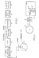
- the engine (not shown) has a crankshaft to which is fixed a disc 10.
- the disc has a toothed circumference and co-operates with a sensor 11, for instance a variable reluctance transducer, so as to provide a pulsed electrical signal with each pulse corresponding to the passage of a tooth past the sensor.
- a sensor 11 for instance a variable reluctance transducer
- the output of the sensor 11 is connected to an input circuit 12 which includes pulse shaping circuitry for converting the analog sensor signal into a digital output signal.
- the digital output signal is supplied to a timer 13 which times the passage of one or a plurality of teeth past the sensor 11. For instance, as indicated in Figure 1, the fire period corresponding to 120° rotation of the crankshaft following detection of each of the three teeth is measured by the timer 13 and supplied to a misfire detection circuit 14.
- the misfire detection circuit 14 forms the reciprocal of each fire period so as to provide an indication of engine speed during each ignition stroke of the engine and allocates the speed measurements consecutively to three series of measurements corresponding to measurement periods defined by passage of the three teeth of the disc 10 shown in Figure 1 past the sensor 11.
- the circuit 14 is arranged to form the differences between consecutive pairs of speed measurements in each series.
- the three sets of speed differences are supplied to a comparator within the detector 14 which compares each speed difference with a fixed threshold, for instance corresponding to a variation of 15 RPM. Whenever a speed difference exceeds the threshold, the comparator supplies a signal to an averaging engine 15.
- a threshold for instance corresponding to a variation of 15 RPM.
- the averaging circuit 15 acts as a low pass filter whose purpose is to avoid unwanted misfire indication in conditions where misfire is not present for long enough to cause substantial damage to the catalyst or unacceptably high levels of undesirable exhaust emissions.
- the output of the averaging circuit gives an indication of the percentage of misfire and is connected to a comparator 16.
- the comparator 16 compares the percentage of misfire with a fixed threshold, for instance representing 5% of misfire, corresponding to the level above which damage to the catalyst and/or excessive hydrocarbons emissions could occur. When the threshold is exceeded, the comparator 16 supplies a signal to a misfire indicator 17 which provides a visible and/or audible indication.
- the misfire detector shown in Figure 1 can be implemented as an analogue circuit, a discrete hard wired digital circuit, or a combination of the two, it is preferably implemented as a programmed micro-controller-based system as shown in Figure 2.
- the sensor 11 is connected to an input interface 12 whose output is connected to an engine management system 20 which controls ignition timing and fuelling of the internal combustion engine.
- the engine management system 20 includes a micro-controller 21 whose operation is controlled by a program stored in a read-only memory 22.
- the micro-controller 21 has a timer input TIMER to which the output of the input interface 12 is connected.
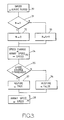
- the micro-controller 21 performs an interrupt request routine in response to the leading edge of each pulse produced by the sensor 11 and processed by the input interface 12 as a tooth of the disc 10 begins to pass the sensor 11.
- the timed fire period is converted into engine speed by dividing a constant K by the fire period in a step 30.
- a decision step 31 determines which of the teeth 0, 1, 2 triggered the fire period determination which has just been completed by ascribing a number N to passages of these three teeth past the sensor 11. If N is equal to two, the value of N is reset to zero in a step 32. If N is not equal to 2, then the value of N is incremented by 1 in a step 33.
- a speed change is then determined by subtracting the speed determined in the step 30 from the previously stored value of the speed for the tooth N in a step 34.
- a step 35 determines whether the speed change is greater than a threshold, for instance corresponding to a speed variation of 15 RPM. If the speed change is less than the threshold, a misfire flag is set to false in a step 36. If the speed change exceeds the threshold, the misfire flag is set to true in a step 37.
- the stored speed for the tooth N is then up-dated at 38 by replacing the previous value with the value calculated in the step 30.
- the interrupt routine is then terminated and control passes to the other software resident in the read only memory 22.
- Figure 4 shows a graph of engine speed against time with each ignition stroke being indicated on the time axis.
- each complete cycle of the engine is represented by a letter A, B, C... and each cylinder ignition stroke is indicated by a subscript in the order of firing of the cylinders.
- A1 represents the ignition stroke of the first piston in engine cycle A
- A2 represents the ignition stroke of the second cylinder in engine cycle A
- B1 represents the first ignition stroke in engine cycle B, and so on.
- the timer resolution which, in turn, defines the speed measurement resolution, is indicated at 40.
- the graph in Figure 4 thus shows individual cylinder speed variations for the engine under low load conditions and at an engine speed of 5,000 RPM. An engine misfire is deliberately introduced at the rate of one misfire for twenty ignition strokes so as to illustrate the effect on engine speed.
- Figure 5 illustrates misfire detection with the engine running in the same operating conditions and at the same rate of misfires as in Figure 4.
- the curves represent numbers of detections of misfires over a period of engine operation when 200 misfires actually took place, as indicated by the chain dot line in Figure 5.
- the full line representing "valid" misfire detections illustrates how the number of detected misfires is related to the actual value of the threshold against which comparison of engine speed variations is made.
- the broken line representing "false” misfire detections was obtained under the same test conditions but without any misfire being generated. If the detection threshold is set to too high a value, for instance 25 RPM, the number of detected misfires is far too small, of the order of 20 to 30 misfire detections when in fact 200 misfires took place. The comparison is therefore too insensitive and misses approximately 90% of the actual misfires which occurred during the measurement period.
- the detection threshold is set to a relatively low value, such as 5 RPM, the detector indicates false misfires.
- the comparison is therefore too sensitive and relatively small speed variations which occur naturally during engine operation have been falsely detected as misfires. Also, the tendency for engine speed remaining low during ignition strokes following a misfire is resulting in several misfires being detected when in fact only one misfire has occurred. These extra detections are not in fact erroneous but represent "second order" effects of the misfire.
- a detection threshold of between 15 and 20 RPM is appropriate and, in fact, a detection threshold of 15 RPM allows misfire to be detected with very good reliability and consistency, the curve of false detection in Figure 5 indicating that, with this threshold, false misfire detections are non-existent.
- Figure 6 is similar to Figure 5 but illustrates the effect of varying the detection threshold for the engine operating under low load at a speed of 3,000 RPM. Again, the actual number of misfires which occurred during the measurement period is indicated by the chain dot line. Engine operation with a single misfire every 35 ignition strokes is illustrated by the full line and operation with two consecutive misfires occurring every 70 ignition strokes is illustrated by the broken line.
- the curve representing single misfires is similar to the "valid" curve of Figure 5 and indicates that a threshold of 15 RPM gives reliable and consistent detection of misfires. The curve representing double misfires gives approximately the same detection of misfires for this threshold.
- the operation of the misfire detector shown in Figures 1 and 2 differs from that described hereinbefore as follows.
- the misfire detection circuit 14 forms the reciprocal of each fire period so as to provide an indication of engine speed during each ignition stroke of the engine and forms a speed change signal as T(x)-T(x+1)-T(x+a)+T(x+a+1), where a is the number of engine fires per revolution of the crankshaft.
- the speed change or difference signal is supplied to the comparator within the detector 14 which compares each speed difference with a fixed threshold, for instance corresponding to a variation of 20 RPM. Whenever a speed difference exceeds the threshold, the comparator supplies a signal to the averaging engine 15.
- the timed fire period is converted into engine speed by dividing a constant K by the fire period in a step 130.
- a speed change is then determined in a step 131 as T(x)-T(x+1)-T(x+a)+T(x+a+1), where a is the number of engine fires per revolution of the crankshaft.
- a step 135 determines whether the speed change is greater than a threshold, for instance corresponding to a speed variation of 20 RPM. If the speed change is less than the threshold, a misfire flag is set to false in a step 136. If the speed change exceeds the threshold, the misfire flag is set to true in a step 137. The index x is then up-dated in a step 138. The interrupt routine is then terminated and control passes to the other software resident in the read only memory 22.
- Figure 8 illustrates the algorithm performed in the step 131 in Figure 7.
- the upper row represents the crankshaft segments a, b, c used for providing period measurement information and corresponding to sections of the circumference of the crankshaft disc 10 beginning with the teeth 0, 1, 2 shown in Figure 1.
- the next row indicates the measured periods of passage of these sections as P A to P D
- the bottom row represents a smoothed curve of engine output speed illustrating a misfire occurring during the period P A .
- P A corresponds to T(x)
- P B corresponds to T(x+1)
- P C corresponds to T(x+a)
- P D corresponds to T(x+a+1) for a six cylinder four-stroke engine.
- adjacent measured periods may be compared. This is because of the sharp drop in speed and slow speed recovery occurring after a misfire, as illustrated in the bottom row of Figure 8. Comparing period measurements spaced apart by several fire cycles of the engine could result in spurious misfire detection, but comparison of adjacent periods allows identification of the misfiring cylinder.
- a further advantage of this algorithm is that errors due to linear acceleration and deceleration are also cancelled greatly reduced.
- Figure 9 illustrates the number of misfire detections against the threshold in revolutions per minute (RPM) for the step 135 in Figure 7.
- RPM revolutions per minute
- the operation of the misfire detector shown in Figures 1 and 2 differs from that described hereinbefore as follows.
- the circuit 14 forms the sum of the engine speeds corresponding to the fire period just determined and the fire period five firing cycles of the engine earlier and subtracts from this the sum of the speeds corresponding to the firing periods two and three firing cycles of the engine earlier.
- This calculation provides a speed variation signal which is compared within the detector 14 with a threshold value, for instance corresponding to speed variation of 18 RPM. Whenever the speed difference exceeds this threshold, the comparator supplies a signal to an averaging circuit 15.
- the detection of a misfire can readily be correlated with the cylinder which has just produced a combustion event so that a misfiring cylinder and piston can be identified. For consecutive misfire detections, cylinder identification can be performed as will be described hereinafter.
- the timed fire period is converted into engine speed by dividing a constant K by the fire period in a step 230.
- a speed change is determined as S(x-2)+S(x-3)-S(x)-S(x-5) in a step 231, the speeds S (x-2), S(x-3), and S(x-5) having been obtained in the step 230 during the second, third, and fifth preceding cycles of operation.
- a step 235 determines whether the speed change is greater than a threshold, for instance corresponding to a speed variation of 18 RPM. If the speed change is less than the threshold, a misfire flag is set to false in a step 236. If the speed change exceeds the threshold, the misfire flag is set to true in a step 237. Finally, a step 238 resets the index x in readiness for a succeeding cycle of operation. The interrupt routine is then terminated and control passes to the other software resident in the read only memory 22.
- a threshold for instance corresponding to a speed variation of 18 RPM.
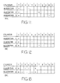
- Figures 11 to 13 are tables illustrating the derivation of the calculation performed in the step 231 of Figure 10.
- fire periods are compared by making measurements over the same physical portion of the disc 10.
- the measurements which are compared should be located at every third fire cycle or an integer multiple of this.
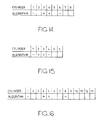
- Figures 14 to 16 illustrate examples of the actual algorithms which may be used in the step 231 for different engine sizes.
- Figure 14 illustrates the present case for a six cylinder in line engine.
- Figure 15 illustrates the corresponding algorithm for a four cylinder engine and
- Figure 16 illustrates the algorithm for an eight cylinder engine. Suitable algorithms for other types of engines can readily be obtained.
- the algorithms shown in Figures 14 to 16 represent composites of the techniques illustrated in Figures 11 to 13.
- the algorithm of Figure 14 represents a composite of the algorithms shown in Figures 11 to 13.
- a composite algorithm which fully combines the algorithms shown in Figures 11 to 13 can be provided for any engine having an even number of cylinders. For an engine with an odd number of cylinders, this is not possible and an algorithm has to be provided representing any two of the three types of algorithms illustrated in Figures 11 to 13. The actual choice of which two algorithms should be combined depends on circumstances and, in particular, which of the three difficulties overcome by the algorithms of Figures 11 to 13 is least important for the particular application. For instance, if the engine does not exhibit crankshaft vibrations for alternate firing periods, algorithms from Figures 11 and 13 may be combined as a composite algorithm for an engine with an odd number of cylinders.
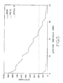
- Figure 17 illustrates the effect of selecting the threshold against which the speed change signal is compared in the step 235 of Figure 10.
- the vertical axis represents the numbers of misfire detections and the horizontal axis represents the threshold in terms of revolutions per minute (RPM).
- RPM revolutions per minute
- the curves were obtained for an engine running at 2,000 RPM for a period corresponding to 4,000 engine fire cycles.
- the curve labelled "Tarmac” indicates operation of an engine running along a smooth tarmac road with no misfires. From this, it can be seen that thresholds less than about 11 RPM will give rise to spurious misfire detections.
- the curve labelled "Rough Road” represents a vehicle running along a relatively rough surface, and illustrates that spurious misfire detections will take place below a threshold of about 16 RPM.
- the curve labelled "1/101 Misfire” represents the occurrence of one actual misfire per 101 fire cycles, and the curve “1/48 Misfire” likewise relates to one misfire per 48 firing cycles. From these curves, it can be seen that a threshold level of 18 RPM will detect approximately the correct number of misfires and will not detect many, if any, spurious misfires. Above a threshold level of about 20 RPM, substantial numbers of misfires are not detected. Thus, the optimum threshold level for the arrangement which gave rise to the results shown in Figure 17 is 18 or 19 RPM.
- the threshold level should not be reduced to the point where spurious detections not associated with actual misfires occur.
- a threshold level below about 15 RPM would give rise to such spurious detection, for instance caused by movement over a rough road surface. It may therefore be more appropriate to set the threshold level at 15 or 16 RPM in order to avoid detecting any significant number of spurious misfires while ensuring that all actual misfires are detected.
- Figure 18 illustrates the results of a test on an engine during which 500 actual misfires took place.
- the first column indicates different threshold levels and the second column indicates the total number of misfire detections.
- the remaining columns indicate the total number of misfires detected for each cylinder.
- threshold levels below 12 RPM
- misfires were detected for cylinders numbers 3, 4, and 5.
- this threshold misfires were detected in cylinders 3 and 4 only. In fact, the same numbers of misfires were detected in these two cylinders, and occurred as pairs of misfires during consecutive combustion events. In fact, only cylinder 3 was subjected to misfiring.
- an algorithm which may be added to the flow diagram of Figure 10 searches for consecutive misfire detections and then ascribes the misfire to the first of the two cylinders involved in the combustion events. Thus, if a misfire is detected in cylinder firing cycle i and again cylinder firing cycle (i+1), then the algorithm determines that the misfire was actually detected in respect of cylinder i. If consecutive misfires occur for more than two consecutive firing cycles, the above algorithm operates on the first and second such misfire detections, and then on the second and third misfire detections, and so on for any succeeding misfires.
- Detection of misfires may be used in various ways.
- the engine management system 20 may be alerted to the misfires and may be arranged to take, or attempt to take, remedial action, such as changing the air/fuel ratio or ignition timing or, for a persistently misfiring cylinder, cutting off the supply of fuel to that cylinder.
- a visual and/or audible indication may be given to a driver of a vehicle so as to alert the driver to a possible problem.
- Misfires may be recorded in a memory within the engine management system 20 and may be made accessible to service personnel so as to permit efficient and possibly early diagnosis of potential problems in engine operation.
Landscapes
- Chemical & Material Sciences (AREA)
- Engineering & Computer Science (AREA)
- Combustion & Propulsion (AREA)
- Physics & Mathematics (AREA)
- General Physics & Mathematics (AREA)
- Combined Controls Of Internal Combustion Engines (AREA)
- Ignition Installations For Internal Combustion Engines (AREA)
Applications Claiming Priority (6)
| Application Number | Priority Date | Filing Date | Title |
|---|---|---|---|
| GB909003387A GB9003387D0 (en) | 1990-02-14 | 1990-02-14 | Method of and apparatus for detecting misfire |
| GB9003387 | 1990-02-14 | ||
| GB909021226A GB9021226D0 (en) | 1990-09-28 | 1990-09-28 | Method of and apparatus for detecting misfire |
| GB9021225 | 1990-09-28 | ||
| GB9021226 | 1990-09-28 | ||
| GB909021225A GB9021225D0 (en) | 1990-09-28 | 1990-09-28 | Method of and apparatus for detecting misfire |
Publications (3)
| Publication Number | Publication Date |
|---|---|
| EP0442687A2 true EP0442687A2 (de) | 1991-08-21 |
| EP0442687A3 EP0442687A3 (en) | 1992-09-02 |
| EP0442687B1 EP0442687B1 (de) | 1998-04-15 |
Family
ID=27264941
Family Applications (1)
| Application Number | Title | Priority Date | Filing Date |
|---|---|---|---|
| EP91301094A Expired - Lifetime EP0442687B1 (de) | 1990-02-14 | 1991-02-12 | Vorrichtung zur Detektierung von Fehlzündungen |
Country Status (5)
| Country | Link |
|---|---|
| US (1) | US5237504A (de) |
| EP (1) | EP0442687B1 (de) |
| JP (1) | JPH04219448A (de) |
| CA (1) | CA2036244A1 (de) |
| DE (1) | DE69129245T2 (de) |
Cited By (6)
| Publication number | Priority date | Publication date | Assignee | Title |
|---|---|---|---|---|
| EP0497475A2 (de) * | 1991-02-01 | 1992-08-05 | Lucas Industries Public Limited Company | Einrichtung zur Behandlung von Geschwindigkeitsdata einer inneren Brennkraftmaschine |
| WO1993011356A1 (de) * | 1991-12-05 | 1993-06-10 | Robert Bosch Gmbh | Zündanlage für brennkraftmaschinen |
| US5275037A (en) * | 1991-06-12 | 1994-01-04 | Nippondenso Co., Ltd. | Apparatus for detecting misfire in internal combustion engine |
| EP0585762A1 (de) * | 1992-08-21 | 1994-03-09 | Chrysler Corporation | Verfahren und Vorrichtung zum Erfassen von Verbrennungsaussetzern in einer Brennkraftmaschine mittels eines Sensors |
| EP0594330A2 (de) * | 1992-10-21 | 1994-04-27 | Lucas Industries Public Limited Company | Vorrichtung und Verfahren zum Erfassen von Verbrennungsauszetsern |
| EP0637738A1 (de) * | 1993-08-04 | 1995-02-08 | CENTRO RICERCHE FIAT Società Consortile per Azioni | Verfahren und System zur Erfassung von Verbrennungsaussetzern bei Ottomotoren |
Families Citing this family (40)
| Publication number | Priority date | Publication date | Assignee | Title |
|---|---|---|---|---|
| US5487008A (en) * | 1990-04-20 | 1996-01-23 | The Regents Of The University Of Michigan | Method and system for detecting the misfire of a reciprocating internal combustion engine in frequency domain |
| US5452698A (en) * | 1990-05-07 | 1995-09-26 | Robert Bosch Gmbh | Device for suppressing discontinuous motion of a moving motor vehicle |
| DE4206118C2 (de) * | 1991-02-27 | 1996-11-14 | Mitsubishi Electric Corp | Fehlzündungsdetektorvorrichtung für einen Verbrennungsmotor |
| JP2606019B2 (ja) * | 1991-09-18 | 1997-04-30 | 三菱電機株式会社 | 内燃機関の失火検出装置 |
| JPH05214985A (ja) * | 1992-02-05 | 1993-08-24 | Fuji Heavy Ind Ltd | エンジンの燃料噴射制御方法 |
| EP0609451B1 (de) * | 1992-06-09 | 1997-09-10 | Mitsubishi Jidosha Kogyo Kabushiki Kaisha | Verfahren zur erkennung von fehlzündungen durch drehzahländerung der kurbelwelle |
| WO1993025809A1 (en) * | 1992-06-16 | 1993-12-23 | Mitsubishi Jidosha Kogyo Kabushiki Kaisha | Misfire detecting method |
| DE59204440D1 (de) * | 1992-08-14 | 1996-01-04 | Siemens Ag | Verfahren zur Erkennung von Verbrennungsaussetzern. |
| CA2104144C (en) * | 1992-08-21 | 2004-01-06 | Jay C. Mccombie | Dual sensor misfire detection apparatus and method for an internal combustion engine |
| US5446664A (en) * | 1992-10-07 | 1995-08-29 | Spx Corporation | Method and apparatus for diagnosing faulty cylinders in internal combustion engines |
| JP2856014B2 (ja) * | 1993-02-05 | 1999-02-10 | 三菱自動車工業株式会社 | クランク軸回転変動による失火検出方法 |
| JPH07103055A (ja) * | 1993-09-30 | 1995-04-18 | Fuji Heavy Ind Ltd | エンジンの定常運転判別方法 |
| JP3381179B2 (ja) * | 1993-10-05 | 2003-02-24 | 株式会社日立製作所 | 車両状態検出装置及び検出方法 |
| US5509302A (en) * | 1994-05-02 | 1996-04-23 | Saturn Corporation | Misfire detection in internal combustion engines |
| GB9413677D0 (en) * | 1994-07-07 | 1994-08-24 | Lucas Ind Plc | Method of and apparatus for calibrating rotary position transducers |
| US5445014A (en) * | 1994-08-12 | 1995-08-29 | Briggs & Stratton Corporation | Electronic engine load and revolution sensing device |
| US5576963A (en) * | 1994-10-18 | 1996-11-19 | Regents Of The University Of Michigan | Method and system for detecting the misfire of a reciprocating internal combustion engine utilizing a misfire index model |
| GB9504625D0 (en) * | 1995-03-08 | 1995-04-26 | Lucas Ind Plc | Fuel system |
| US5806014A (en) * | 1995-05-01 | 1998-09-08 | Motorola Inc. | Combustion control of an internal combustion engine proximate an extinction limit |
| US5668725A (en) * | 1995-11-13 | 1997-09-16 | General Motors Corporation | Internal combustion engine misfire detection |
| US6062071A (en) * | 1995-11-30 | 2000-05-16 | Siemens Aktiengesellschaft | Method for detecting combustion misfires in an internal combustion engine |
| US5735246A (en) * | 1996-09-30 | 1998-04-07 | Chrysler Corporation | Fuel scheduling as a function of misfire rate |
| DE19641916B4 (de) * | 1996-10-11 | 2008-03-06 | Robert Bosch Gmbh | Verfahren zur Verbrennungsaussetzererkennung durch Auswertung von Drehzahlschwankungen |
| US5979407A (en) * | 1998-06-01 | 1999-11-09 | Cummins Engine Company, Inc. | Passive and active misfire diagnosis for internal combustion engines |
| DE10254479B4 (de) * | 2002-11-21 | 2004-10-28 | Siemens Ag | Verfahren zum Erkennen von Verbrennungsaussetzern in einer Brennkraftmaschine |
| US7006912B2 (en) * | 2003-05-29 | 2006-02-28 | Cummins Inc. | Cylinder misfire diagnostic system |
| US7353803B2 (en) * | 2005-12-20 | 2008-04-08 | Gm Global Technology Operations, Inc. | Misfire detection apparatus for internal combustion engine based on piston speed |
| US8060275B2 (en) * | 2007-01-19 | 2011-11-15 | Ford Global Technologies, Llc | Rough road detection system used in an on-board diagnostic system |
| JP2009121303A (ja) * | 2007-11-14 | 2009-06-04 | Denso Corp | 内燃機関の失火検出装置 |
| US8046155B2 (en) * | 2009-02-13 | 2011-10-25 | Denso Corporation | Method and apparatus for misfire detection using engine cycles at least subsequent to actual misfire event |
| US20110043349A1 (en) * | 2009-08-24 | 2011-02-24 | Lawrence Antony Johnson | Active Wide-band Air Fuel Ratio Indicator |
| JP5488286B2 (ja) * | 2010-07-15 | 2014-05-14 | トヨタ自動車株式会社 | 内燃機関の燃焼状態検出システム |
| US20140277997A1 (en) * | 2013-03-15 | 2014-09-18 | Mark Shaffer | Electronic Detection of Engine Malfunction |
| US10591387B2 (en) * | 2013-08-22 | 2020-03-17 | Ford Global Technologies, Llc | Signal classification |
| CN108431389B (zh) * | 2015-07-22 | 2021-11-09 | 沃尔布罗有限责任公司 | 发动机控制策略 |
| KR102406503B1 (ko) * | 2016-12-14 | 2022-06-10 | 현대자동차주식회사 | 점화시기 보정을 통한 촉매 손상 방지 방법 |
| US10731621B2 (en) * | 2016-12-21 | 2020-08-04 | Caterpillar Inc. | Ignition system having combustion initiation detection |
| KR102085896B1 (ko) * | 2018-12-07 | 2020-03-06 | 현대오트론 주식회사 | 파워트레인 엔진 정밀 제어방법 및 이에 의해 운용되는 자동차 |
| US11172288B1 (en) * | 2020-07-14 | 2021-11-09 | Acoustic Metamaterials LLC | Methods and systems for modifying acoustics of a loudspeaker back enclosure using active noise control |
| JP7420053B2 (ja) * | 2020-11-09 | 2024-01-23 | トヨタ自動車株式会社 | 内燃機関の失火検出装置 |
Citations (8)
| Publication number | Priority date | Publication date | Assignee | Title |
|---|---|---|---|---|
| DE3615547A1 (de) * | 1985-05-09 | 1986-11-13 | Nippondenso Co. Ltd., Kariya, Aichi | Vorrichtung zur erkennung eines fehlerhaft arbeitenden zylinders eines mehrzylinder-verbrennungsmotors, sowie verfahren zum betreiben der vorrichtung |
| DE3724420A1 (de) * | 1987-07-23 | 1989-02-02 | Audi Ag | Verfahren zum schutz eines abgaskatalysators einer mehrzylinder-brennkraftmaschine mit fremdzuendung |
| EP0306905A2 (de) * | 1987-09-09 | 1989-03-15 | Jenbacher Werke AG | Einrichtung zur Erkennung von Zünd- und Entflammaussetzern |
| US4899579A (en) * | 1988-10-03 | 1990-02-13 | Ford Motor Company | Onboard diagnostic system of vehicle ignition system |
| EP0403212A2 (de) * | 1989-06-13 | 1990-12-19 | Hitachi, Ltd. | Steuerungsanlage eines Motors |
| DE4009285A1 (de) * | 1989-08-23 | 1990-12-20 | Audi Ag | Verfahren zur zylinderselektiven ueberwachung des energieumsatzes bei einer mehrzylinder-brennkraftmaschine |
| EP0433690A2 (de) * | 1989-11-22 | 1991-06-26 | Unisia Jecs Corporation | Verfahren und Vorrichtung zur Erkennung von Fehlzündung in einem Zylinder einer Brennkraftmaschine |
| EP0437212A2 (de) * | 1990-01-09 | 1991-07-17 | Unisia Jecs Corporation | Verfahren zur Detektierung eines Verbrennungsdefekts in einem Zylinder einer inneren Brennkraftmaschine |
Family Cites Families (12)
| Publication number | Priority date | Publication date | Assignee | Title |
|---|---|---|---|---|
| US4532592A (en) * | 1982-12-22 | 1985-07-30 | Purdue Research Foundation | Engine-performance monitor and control system |
| US4532798A (en) * | 1983-06-08 | 1985-08-06 | Nippon Soken, Inc. | Measurement of variations in internal combustion engine output |
| JPH0733809B2 (ja) * | 1984-06-27 | 1995-04-12 | 株式会社日本自動車部品総合研究所 | 内燃機関の出力変動測定方法 |
| GB8715130D0 (en) * | 1987-06-27 | 1987-08-05 | Lucas Ind Plc | Adaptive control system for i c engine |
| JPH086667B2 (ja) * | 1988-04-15 | 1996-01-29 | 株式会社日立製作所 | 内燃機関の点火時期制御装置 |
| US4930479A (en) * | 1988-05-24 | 1990-06-05 | Toyota Jidosha Kabushiki Kaisha | Irregular combustion determining device for an internal combustion engine |
| DE3923757A1 (de) * | 1988-07-20 | 1990-01-25 | Mitsubishi Electric Corp | Kraftstoffregler fuer brennkraftmaschinen |
| DE68904840T2 (de) * | 1988-08-08 | 1993-07-15 | Hitachi Ltd | Geraet zur erfassung von verbrennungsausfaellen und steuerungssystem fuer einen verbrennungsmotor. |
| JP2510250B2 (ja) * | 1988-08-30 | 1996-06-26 | 日産自動車株式会社 | 内燃機関の燃焼制御装置 |
| JPH0737789B2 (ja) * | 1988-10-17 | 1995-04-26 | 株式会社日立製作所 | 複数気筒エンジンの電子式制御装置 |
| US4936277A (en) * | 1988-12-19 | 1990-06-26 | Motorola, Inc. | System for monitoring and/or controlling multiple cylinder engine performance |
| US4932379A (en) * | 1989-05-01 | 1990-06-12 | General Motors Corporation | Method for detecting engine misfire and for fuel control |
-
1991
- 1991-02-12 EP EP91301094A patent/EP0442687B1/de not_active Expired - Lifetime
- 1991-02-12 DE DE69129245T patent/DE69129245T2/de not_active Expired - Lifetime
- 1991-02-13 US US07/655,568 patent/US5237504A/en not_active Expired - Fee Related
- 1991-02-13 CA CA002036244A patent/CA2036244A1/en not_active Abandoned
- 1991-02-14 JP JP3021216A patent/JPH04219448A/ja active Pending
Patent Citations (8)
| Publication number | Priority date | Publication date | Assignee | Title |
|---|---|---|---|---|
| DE3615547A1 (de) * | 1985-05-09 | 1986-11-13 | Nippondenso Co. Ltd., Kariya, Aichi | Vorrichtung zur erkennung eines fehlerhaft arbeitenden zylinders eines mehrzylinder-verbrennungsmotors, sowie verfahren zum betreiben der vorrichtung |
| DE3724420A1 (de) * | 1987-07-23 | 1989-02-02 | Audi Ag | Verfahren zum schutz eines abgaskatalysators einer mehrzylinder-brennkraftmaschine mit fremdzuendung |
| EP0306905A2 (de) * | 1987-09-09 | 1989-03-15 | Jenbacher Werke AG | Einrichtung zur Erkennung von Zünd- und Entflammaussetzern |
| US4899579A (en) * | 1988-10-03 | 1990-02-13 | Ford Motor Company | Onboard diagnostic system of vehicle ignition system |
| EP0403212A2 (de) * | 1989-06-13 | 1990-12-19 | Hitachi, Ltd. | Steuerungsanlage eines Motors |
| DE4009285A1 (de) * | 1989-08-23 | 1990-12-20 | Audi Ag | Verfahren zur zylinderselektiven ueberwachung des energieumsatzes bei einer mehrzylinder-brennkraftmaschine |
| EP0433690A2 (de) * | 1989-11-22 | 1991-06-26 | Unisia Jecs Corporation | Verfahren und Vorrichtung zur Erkennung von Fehlzündung in einem Zylinder einer Brennkraftmaschine |
| EP0437212A2 (de) * | 1990-01-09 | 1991-07-17 | Unisia Jecs Corporation | Verfahren zur Detektierung eines Verbrennungsdefekts in einem Zylinder einer inneren Brennkraftmaschine |
Cited By (12)
| Publication number | Priority date | Publication date | Assignee | Title |
|---|---|---|---|---|
| EP0497475A2 (de) * | 1991-02-01 | 1992-08-05 | Lucas Industries Public Limited Company | Einrichtung zur Behandlung von Geschwindigkeitsdata einer inneren Brennkraftmaschine |
| EP0497475B1 (de) * | 1991-02-01 | 1999-04-21 | Lucas Industries Public Limited Company | Verfahren und Einrichtung zur Bestimmung von Oberflächenrauhigkeit |
| US5275037A (en) * | 1991-06-12 | 1994-01-04 | Nippondenso Co., Ltd. | Apparatus for detecting misfire in internal combustion engine |
| WO1993011356A1 (de) * | 1991-12-05 | 1993-06-10 | Robert Bosch Gmbh | Zündanlage für brennkraftmaschinen |
| US5490489A (en) * | 1991-12-05 | 1996-02-13 | Robert Bosch Gmbh | Ignition system for an internal combustion engine |
| EP0585762A1 (de) * | 1992-08-21 | 1994-03-09 | Chrysler Corporation | Verfahren und Vorrichtung zum Erfassen von Verbrennungsaussetzern in einer Brennkraftmaschine mittels eines Sensors |
| US5361629A (en) * | 1992-08-21 | 1994-11-08 | Chrysler Corporation | Single sensor misfire detection apparatus and method for an internal combustion engine |
| EP0594330A2 (de) * | 1992-10-21 | 1994-04-27 | Lucas Industries Public Limited Company | Vorrichtung und Verfahren zum Erfassen von Verbrennungsauszetsern |
| EP0594330A3 (en) * | 1992-10-21 | 1994-06-01 | Lucas Ind Plc | Method of and apparatus for discriminating misfire |
| US5425269A (en) * | 1992-10-21 | 1995-06-20 | Lucas Industries Public Limited Company | Method of and apparatus for discriminating misfire |
| EP0637738A1 (de) * | 1993-08-04 | 1995-02-08 | CENTRO RICERCHE FIAT Società Consortile per Azioni | Verfahren und System zur Erfassung von Verbrennungsaussetzern bei Ottomotoren |
| US5515281A (en) * | 1993-08-04 | 1996-05-07 | Centro Richerche Fiat Societa' Sortile Per Azioni | Process and system for detecting misfiring in internal combustion engines |
Also Published As
| Publication number | Publication date |
|---|---|
| US5237504A (en) | 1993-08-17 |
| DE69129245D1 (de) | 1998-05-20 |
| DE69129245T2 (de) | 1998-08-06 |
| CA2036244A1 (en) | 1991-08-15 |
| JPH04219448A (ja) | 1992-08-10 |
| EP0442687A3 (en) | 1992-09-02 |
| EP0442687B1 (de) | 1998-04-15 |
Similar Documents
| Publication | Publication Date | Title |
|---|---|---|
| US5237504A (en) | Method of and apparatus for detecting misfire | |
| US5109695A (en) | Misfire detection in an internal combustion engine | |
| US5095742A (en) | Determining crankshaft acceleration in an internal combustion engine | |
| US5044195A (en) | Misfire detection in an internal combustion engine | |
| AU644103B2 (en) | Engine diagnostic apparatus and method | |
| US5485374A (en) | Combustion-conditon diagnostic system and method for a multicylinder engine | |
| US5804711A (en) | Pattern recognition method and system for determining a misfire condition in a reciprocating engine | |
| US5824890A (en) | Real time misfire detection for automobile engines | |
| JP2982381B2 (ja) | 内燃機関用失火検出装置 | |
| CA2104144C (en) | Dual sensor misfire detection apparatus and method for an internal combustion engine | |
| US5222392A (en) | Control system with misfire detection function for internal combustion engine | |
| EP0716298A2 (de) | Erkennen von Verbrennungsaussetzern in inneren Verbrennungsmotoren | |
| EP0551764A2 (de) | Verfahren und Vorrichtung für Detektion von unebener Strasse und Zündaussetzern | |
| US6725709B2 (en) | Combustion state diagnosing system and combustion state diagnosing method for diagnosing engine and recording medium | |
| US5499537A (en) | Apparatus for detecting misfire in internal combustion engine | |
| DE4139161A1 (de) | Fehlzuendungserfassungsvorrichtung fuer eine brennkraftmaschine | |
| US5717133A (en) | Mixed sampling rate processing for misfire detection | |
| US5493901A (en) | Combustion state-detecting system for internal combustion engines | |
| WO1997019334A1 (en) | Detrending engine positional data for rotating position encoders | |
| EP0660099B1 (de) | Fehlzündungserkennung bei einer inneren Brennkraftmaschine | |
| JPH08312445A (ja) | 燃焼中の失火識別方法 | |
| GB2337136A (en) | Regulating an engine using a transmitter wheel with a reference mark | |
| WO2006116787A2 (de) | Verfahren zur erkennung von reaktiven gasanteilen im abgas einer brennkraftmaschine |
Legal Events
| Date | Code | Title | Description |
|---|---|---|---|
| PUAI | Public reference made under article 153(3) epc to a published international application that has entered the european phase |
Free format text: ORIGINAL CODE: 0009012 |
|
| AK | Designated contracting states |
Kind code of ref document: A2 Designated state(s): DE ES FR GB IT SE |
|
| PUAL | Search report despatched |
Free format text: ORIGINAL CODE: 0009013 |
|
| AK | Designated contracting states |
Kind code of ref document: A3 Designated state(s): DE ES FR GB IT SE |
|
| 17P | Request for examination filed |
Effective date: 19930216 |
|
| 17Q | First examination report despatched |
Effective date: 19950821 |
|
| GRAG | Despatch of communication of intention to grant |
Free format text: ORIGINAL CODE: EPIDOS AGRA |
|
| GRAG | Despatch of communication of intention to grant |
Free format text: ORIGINAL CODE: EPIDOS AGRA |
|
| GRAH | Despatch of communication of intention to grant a patent |
Free format text: ORIGINAL CODE: EPIDOS IGRA |
|
| RAP1 | Party data changed (applicant data changed or rights of an application transferred) |
Owner name: LUCAS INDUSTRIES PUBLIC LIMITED COMPANY |
|
| GRAH | Despatch of communication of intention to grant a patent |
Free format text: ORIGINAL CODE: EPIDOS IGRA |
|
| GRAA | (expected) grant |
Free format text: ORIGINAL CODE: 0009210 |
|
| AK | Designated contracting states |
Kind code of ref document: B1 Designated state(s): DE ES FR GB IT SE |
|
| PG25 | Lapsed in a contracting state [announced via postgrant information from national office to epo] |
Ref country code: ES Free format text: THE PATENT HAS BEEN ANNULLED BY A DECISION OF A NATIONAL AUTHORITY Effective date: 19980415 |
|
| ITF | It: translation for a ep patent filed |
Owner name: BUGNION S.P.A. |
|
| REF | Corresponds to: |
Ref document number: 69129245 Country of ref document: DE Date of ref document: 19980520 |
|
| ET | Fr: translation filed | ||
| PG25 | Lapsed in a contracting state [announced via postgrant information from national office to epo] |
Ref country code: SE Free format text: LAPSE BECAUSE OF FAILURE TO SUBMIT A TRANSLATION OF THE DESCRIPTION OR TO PAY THE FEE WITHIN THE PRESCRIBED TIME-LIMIT Effective date: 19980715 |
|
| PLBE | No opposition filed within time limit |
Free format text: ORIGINAL CODE: 0009261 |
|
| STAA | Information on the status of an ep patent application or granted ep patent |
Free format text: STATUS: NO OPPOSITION FILED WITHIN TIME LIMIT |
|
| 26N | No opposition filed | ||
| REG | Reference to a national code |
Ref country code: GB Ref legal event code: IF02 |
|
| PGFP | Annual fee paid to national office [announced via postgrant information from national office to epo] |
Ref country code: FR Payment date: 20100316 Year of fee payment: 20 Ref country code: IT Payment date: 20100227 Year of fee payment: 20 |
|
| PGFP | Annual fee paid to national office [announced via postgrant information from national office to epo] |
Ref country code: GB Payment date: 20100205 Year of fee payment: 20 Ref country code: DE Payment date: 20100211 Year of fee payment: 20 |
|
| REG | Reference to a national code |
Ref country code: DE Ref legal event code: R071 Ref document number: 69129245 Country of ref document: DE |
|
| REG | Reference to a national code |
Ref country code: GB Ref legal event code: PE20 Expiry date: 20110211 |
|
| PG25 | Lapsed in a contracting state [announced via postgrant information from national office to epo] |
Ref country code: GB Free format text: LAPSE BECAUSE OF EXPIRATION OF PROTECTION Effective date: 20110211 |
|
| PG25 | Lapsed in a contracting state [announced via postgrant information from national office to epo] |
Ref country code: DE Free format text: LAPSE BECAUSE OF EXPIRATION OF PROTECTION Effective date: 20110212 |