EP0442514A2 - Mechanismus zur Befestigung eines Fotodetektors - Google Patents
Mechanismus zur Befestigung eines Fotodetektors Download PDFInfo
- Publication number
- EP0442514A2 EP0442514A2 EP91102133A EP91102133A EP0442514A2 EP 0442514 A2 EP0442514 A2 EP 0442514A2 EP 91102133 A EP91102133 A EP 91102133A EP 91102133 A EP91102133 A EP 91102133A EP 0442514 A2 EP0442514 A2 EP 0442514A2
- Authority
- EP
- European Patent Office
- Prior art keywords
- photodetector
- base plate
- mounting member
- caul
- screws
- Prior art date
- Legal status (The legal status is an assumption and is not a legal conclusion. Google has not performed a legal analysis and makes no representation as to the accuracy of the status listed.)
- Withdrawn
Links
Images
Classifications
-
- G—PHYSICS
- G11—INFORMATION STORAGE
- G11B—INFORMATION STORAGE BASED ON RELATIVE MOVEMENT BETWEEN RECORD CARRIER AND TRANSDUCER
- G11B7/00—Recording or reproducing by optical means, e.g. recording using a thermal beam of optical radiation by modifying optical properties or the physical structure, reproducing using an optical beam at lower power by sensing optical properties; Record carriers therefor
- G11B7/12—Heads, e.g. forming of the optical beam spot or modulation of the optical beam
- G11B7/13—Optical detectors therefor
-
- H—ELECTRICITY
- H10—SEMICONDUCTOR DEVICES; ELECTRIC SOLID-STATE DEVICES NOT OTHERWISE PROVIDED FOR
- H10F—INORGANIC SEMICONDUCTOR DEVICES SENSITIVE TO INFRARED RADIATION, LIGHT, ELECTROMAGNETIC RADIATION OF SHORTER WAVELENGTH OR CORPUSCULAR RADIATION
- H10F77/00—Constructional details of devices covered by this subclass
- H10F77/50—Encapsulations or containers
Definitions
- the present invention relates to a mechanism for fixing a photodetector for detecting reflected beams from a recording medium on a base plate.
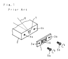
- Fig. 1 is a perspective view showing disassembled parts of the conventional mechanism for fixing a photodetector disclosed in, for example, the Japanese Patent Laid-Open Gazette No. 230632 (1986).
- reference numeral 1 designates a mounting member for fixing a photodetector 1A to a base plate 2.
- base plate 9 At both the lateral ends of the base plate 9 are provided with threaded bores 4a, 4b where two screws 5a, 5b for fixing the mounting member 1 to the base plate 2 are to be screwed.
- a guiding hole 7 At the central portion of the base plate 2 is provided with a guiding hole 7 for guiding the reflected light flux 6 to the photodetector 1A from a recording medium (not shown).
- the mounting member 1 has through bores 3a, 3b through which the screws 5a, 5b perforate, respectively, being provided at the positions corresponding to the respective threaded bores 4a and 4b.
- the photodetector 1A is temporarily disposed by being mounted on the mounting member 1.
- the reflected light flux 6 reflected from a recording medium passes through the guiding hole 7 at the base plate 2 to reach the photodetector 1A.
- the reflected light flux 6 from the recording medium includes the servo information and the reproduced information.
- the position of the photodetector 1A is finely adjusted.
- the screws 5a, 5b are screwed up in the threaded bores 4a, 4b at the base plate 2 through the through bores 3a, 3b at the mounting member 1, respectively thereby fixing the photodetector 1A to the base plate 2.
- the friction coefficient of PPS is generally smaller to an extent of being usable as a base plate substitute for fluoroplastics, whereby a slight variation in the surface condition results in the inequality (1) not being satisfied.
- the conventional photodetector fixing mechanism constructed as above-mentioned has the problem that, when the friction coefficient ⁇ 1 is smaller than ⁇ 2, the mounting member 1 slides against the base plate 2 during fixing the mounting member 1, whereby the positioned photodetector 1A may be shifted due to turns of the screws 5a, 5b.
- the present invention has been designed in order to solve the above problem.
- a main object of the present invention is to provide a photodetector fixing mechanism which prevents a mounting member from shifting due to turns of screws when the mounting member mounted with a photodetector is fixed to a base plate by the screws.
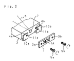
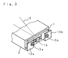
- reference numeral 1 designates a mounting member for fixing a photodetector 1A to a base plate 2.
- the mounting member 1 has through bores 3a, 3b through which the screws 5a, 5b are to perforate, respectively being provided at the positions corresponding to threaded bores 4a, 4b.
- a guiding hole 7 for guiding the reflected light flux 6 to the photodetector 1A from a recording medium (not shown).
- caul portions 10a, 10b In front of the threaded bores 4a, 4b at the base plate 2 are integrally formed therewith caul portions 10a, 10b covering the threaded bores 4a, 4b stood from arm portions which project forwardly from both ends of the lower edge of the base plate 2 so as to keep an interval somewhat greater than a thickness of the mounting member 1 between each caul portion and the base plate 2.
- the caul portions 10a, 10b are provided at the positions corresponding to the threaded bores 4a and 4b with through bores 11a, 11b through which the screws 5a, 5b perforate.
- the caul portions 10a, 10b bend toward the base plate 2 by being subjected to an external pressure to the caul portions in the direction of the thickness thereof, but scarcely deform against a force laterally applied to the caul portions.
- the photodetector 1A is temporarily disposed to the base plate 2 by being mounted on the mounting member 1.
- the mounting position of the photodetector 1A is finely adjusted so that the reflected light flux 6 reflected from a recording medium is incident with accuracy on the photodetector 1A.
- the screws 5a, 5b are screwed in the threaded bores 4a, 4b at the base plate 2 through the through bores 11a, 11b at the caul portions 10a, 10b and through bores 3a, 3b at the mounting member 1, thereby fixing the mounting member 1 to the base plate 2 applying the caul portions 10a, 10b pressed to the mounting member 1 by the screws 5a, 5b.
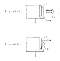
- Fig. 4 is a side view explanatory of the process of disposing the mounting member 1 on the base plate 2.
- the screw 5a is inserted into the through bore 11a at the caul portion 10a and through bore 3a at the mounting member 1 and then tightened.
- the caul portion 10a is deformed by being pushed by the head of the screw 5a and lastly pressed onto the mounting member 1 as shown in Fig. 4(b).
- the photodetector 1A is integrally formed with the mounting member 1, the invention can obtain the same effect as the aforesaid embodiment.
- the through bores 3a, 3b may be formed in any shape and may also be replaced by cutouts through which the screws are passable.
Landscapes
- Physics & Mathematics (AREA)
- Optics & Photonics (AREA)
- Optical Head (AREA)
Applications Claiming Priority (2)
| Application Number | Priority Date | Filing Date | Title |
|---|---|---|---|
| JP15107/90 | 1990-02-16 | ||
| JP1990015107U JPH03106528U (de) | 1990-02-16 | 1990-02-16 |
Publications (2)
| Publication Number | Publication Date |
|---|---|
| EP0442514A2 true EP0442514A2 (de) | 1991-08-21 |
| EP0442514A3 EP0442514A3 (en) | 1991-11-27 |
Family
ID=11879616
Family Applications (1)
| Application Number | Title | Priority Date | Filing Date |
|---|---|---|---|
| EP19910102133 Withdrawn EP0442514A3 (en) | 1990-02-16 | 1991-02-15 | Photodetector fixing mechanism |
Country Status (4)
| Country | Link |
|---|---|
| US (1) | US5111041A (de) |
| EP (1) | EP0442514A3 (de) |
| JP (1) | JPH03106528U (de) |
| CA (1) | CA2036277A1 (de) |
Cited By (1)
| Publication number | Priority date | Publication date | Assignee | Title |
|---|---|---|---|---|
| WO1997008751A1 (en) * | 1995-08-29 | 1997-03-06 | Simage Oy | Imaging system and method |
Families Citing this family (7)
| Publication number | Priority date | Publication date | Assignee | Title |
|---|---|---|---|---|
| US5457314A (en) * | 1991-12-31 | 1995-10-10 | Hyundai Electronics Industries Co., Ltd. | Mount for positioning a photodetector on an optical apparatus |
| EP0727649B1 (de) * | 1995-02-17 | 1998-04-08 | Hewlett-Packard GmbH | Optisches System mit temperaturkompensierter Halterung eines optischen Sensors |
| US6073844A (en) * | 1998-06-19 | 2000-06-13 | Mustek Systems Inc | CCD shift-alignment device for optical scanner |
| US6642511B1 (en) * | 2002-06-13 | 2003-11-04 | Max Data Systems, Inc. | Mounting apparatus for optical sensor having screw piles with annular fitting boards |
| WO2013109815A1 (en) | 2012-01-19 | 2013-07-25 | Volcano Corporation | Interface devices, systems, and methods for use with intravascular pressure monitoring devices |
| WO2014151830A1 (en) | 2013-03-15 | 2014-09-25 | Volcano Corporation | Interface devices, systems, and methods for use with intravascular pressure monitoring devices |
| JP7449158B2 (ja) * | 2020-04-30 | 2024-03-13 | キヤノン株式会社 | 画像形成装置 |
Family Cites Families (10)
| Publication number | Priority date | Publication date | Assignee | Title |
|---|---|---|---|---|
| JPS5927663U (ja) * | 1982-08-12 | 1984-02-21 | キヤノン株式会社 | 画像読取り装置 |
| JPS61131238A (ja) * | 1984-11-30 | 1986-06-18 | Hitachi Ltd | 光学的情報再生装置用ピツクアツプ |
| JPS61230632A (ja) * | 1985-04-05 | 1986-10-14 | Hitachi Ltd | 焦点誤差信号検出装置 |
| JPS6280839A (ja) * | 1985-10-03 | 1987-04-14 | Hitachi Ltd | 光学的情報再生用ピツクアツプとその組付方法 |
| JPS62173862A (ja) * | 1986-01-27 | 1987-07-30 | Sumitomo Electric Ind Ltd | イメ−ジセンサの取付部の構造 |
| JPS63122023A (ja) * | 1986-11-11 | 1988-05-26 | Olympus Optical Co Ltd | 光ピツクアツプにおける光学素子の取付構造 |
| JPS63268130A (ja) * | 1987-04-24 | 1988-11-04 | Mitsubishi Electric Corp | 光検知器の位置調整装置 |
| JP2518213Y2 (ja) * | 1987-07-24 | 1996-11-27 | 三菱電機株式会社 | 光学式ヘッド |
| JPH01133012A (ja) * | 1987-11-19 | 1989-05-25 | Canon Inc | 光検出素子位置決め機構 |
| JPH01269233A (ja) * | 1988-04-20 | 1989-10-26 | Ricoh Co Ltd | 受光素子取付機構 |
-
1990
- 1990-02-16 JP JP1990015107U patent/JPH03106528U/ja active Pending
-
1991
- 1991-02-13 US US07/654,506 patent/US5111041A/en not_active Expired - Fee Related
- 1991-02-13 CA CA002036277A patent/CA2036277A1/en not_active Abandoned
- 1991-02-15 EP EP19910102133 patent/EP0442514A3/en not_active Withdrawn
Non-Patent Citations (6)
| Title |
|---|
| PATENT ABSTRACTS OF JAPAN, unexamined applications, E field, vol. 12, No. 17, January 19, 1988 THE PATENT OFFICE JAPANESE GOVERNMENT page 15 E 574 * |
| PATENT ABSTRACTS OF JAPAN, unexamined applications, P field, vol. 10, No. 324, November 5, 1986 THE PATENT OFFICE JAPANESE GOVERNMENT page 120 P 512 * |
| PATENT ABSTRACTS OF JAPAN, unexamined applications, P field, vol. 11, No. 285, September 16, 1987 THE PATENT OFFICE JAPANESE GOVERNMENT page 63 P 616 * |
| PATENT ABSTRACTS OF JAPAN, unexamined applications, P field, vol. 12, No. 377, October 7, 1988 THE PATENT OFFICE JAPANESE GOVERNMENT page 13 P 768 * |
| PATENT ABSTRACTS OF JAPAN, unexamined applications, P field, vol. 13, No. 85, February 27, 1989 THE PATENT OFFICE JAPANESE GOVERNMENT page 162 P 834 * |
| PATENT ABSTRACTS OF JAPAN, unexamined applications, P field, vol. 14, No. 31, January 22, 1990 THE PATENT OFFICE JAPANESE GOVERNMENT page 98 P 993 * |
Cited By (1)
| Publication number | Priority date | Publication date | Assignee | Title |
|---|---|---|---|---|
| WO1997008751A1 (en) * | 1995-08-29 | 1997-03-06 | Simage Oy | Imaging system and method |
Also Published As
| Publication number | Publication date |
|---|---|
| US5111041A (en) | 1992-05-05 |
| JPH03106528U (de) | 1991-11-05 |
| EP0442514A3 (en) | 1991-11-27 |
| CA2036277A1 (en) | 1991-08-17 |
Similar Documents
| Publication | Publication Date | Title |
|---|---|---|
| JP2662105B2 (ja) | 密着型センサおよびイメージスキャナならびにファクシミリ | |
| EP0442514A2 (de) | Mechanismus zur Befestigung eines Fotodetektors | |
| EP0984673B1 (de) | Rasthaken | |
| US5079577A (en) | Supporting apparatus of flexible printed circuit board of lens barrel | |
| CA2191536A1 (en) | A method and a system of optical disk auto-discrimination | |
| EP0840305A3 (de) | Optisches Gerät | |
| EP0087997A1 (de) | Anordnung zum magnetischen Lesen und/oder Aufzeichnen | |
| KR970063085A (ko) | 광픽업 이송기구 | |
| US5381243A (en) | Arrangement and method for attaching image sensor to electronic machine | |
| US4244109A (en) | Apparatus for mounting and aligning printed circuit board | |
| US5055874A (en) | Film flattening apparatus and method | |
| US5194994A (en) | Mirror installation in an optical device | |
| EP0769779A3 (de) | Magnetkopfzusammenbau | |
| EP0483830A1 (de) | Optischer Kopf | |
| US5197719A (en) | Reference jig for use in mounting lens components in positions, and lens mounting method using such jig | |
| JP3340521B2 (ja) | 走査光学系のカーブドミラー装着構造 | |
| JPH1163966A (ja) | スケール装置 | |
| US5508768A (en) | Camera having a magnetic head | |
| JP3595989B2 (ja) | キャリアのクランプ装置及び方法並びに原盤露光装置 | |
| JPH03165321A (ja) | 部品組立て構造 | |
| KR0181801B1 (ko) | 팩시밀리의 밀착이미지센서 체결장치 | |
| US6126335A (en) | Film holder and image reading device | |
| JP4052182B2 (ja) | センサ用シャッタ体、センサ用部品体、センサ用ホルダ | |
| JP2529346B2 (ja) | 光学ヘッドの部品組付構造ならびに該部品組付用板バネ構造 | |
| JPH02176711A (ja) | コリメータユニツト |
Legal Events
| Date | Code | Title | Description |
|---|---|---|---|
| PUAI | Public reference made under article 153(3) epc to a published international application that has entered the european phase |
Free format text: ORIGINAL CODE: 0009012 |
|
| AK | Designated contracting states |
Kind code of ref document: A2 Designated state(s): DE FR GB |
|
| PUAL | Search report despatched |
Free format text: ORIGINAL CODE: 0009013 |
|
| AK | Designated contracting states |
Kind code of ref document: A3 Designated state(s): DE FR GB |
|
| 17P | Request for examination filed |
Effective date: 19920205 |
|
| 17Q | First examination report despatched |
Effective date: 19940711 |
|
| STAA | Information on the status of an ep patent application or granted ep patent |
Free format text: STATUS: THE APPLICATION IS DEEMED TO BE WITHDRAWN |
|
| 18D | Application deemed to be withdrawn |
Effective date: 19941122 |