EP0441880B1 - Gerät zur durchführung von messungen von elektrolumineszenz-phänomenen - Google Patents
Gerät zur durchführung von messungen von elektrolumineszenz-phänomenen Download PDFInfo
- Publication number
- EP0441880B1 EP0441880B1 EP89912913A EP89912913A EP0441880B1 EP 0441880 B1 EP0441880 B1 EP 0441880B1 EP 89912913 A EP89912913 A EP 89912913A EP 89912913 A EP89912913 A EP 89912913A EP 0441880 B1 EP0441880 B1 EP 0441880B1
- Authority
- EP
- European Patent Office
- Prior art keywords
- voltage waveform
- control signal
- digital
- predetermined voltage
- producing
- Prior art date
- Legal status (The legal status is an assumption and is not a legal conclusion. Google has not performed a legal analysis and makes no representation as to the accuracy of the status listed.)
- Expired - Lifetime
Links
Images




Classifications
-
- H—ELECTRICITY
- H03—ELECTRONIC CIRCUITRY
- H03K—PULSE TECHNIQUE
- H03K4/00—Generating pulses having essentially a finite slope or stepped portions
- H03K4/02—Generating pulses having essentially a finite slope or stepped portions having stepped portions, e.g. staircase waveform
-
- G—PHYSICS
- G01—MEASURING; TESTING
- G01N—INVESTIGATING OR ANALYSING MATERIALS BY DETERMINING THEIR CHEMICAL OR PHYSICAL PROPERTIES
- G01N21/00—Investigating or analysing materials by the use of optical means, i.e. using sub-millimetre waves, infrared, visible or ultraviolet light
- G01N21/62—Systems in which the material investigated is excited whereby it emits light or causes a change in wavelength of the incident light
- G01N21/66—Systems in which the material investigated is excited whereby it emits light or causes a change in wavelength of the incident light electrically excited, e.g. electroluminescence
-
- H—ELECTRICITY
- H03—ELECTRONIC CIRCUITRY
- H03K—PULSE TECHNIQUE
- H03K4/00—Generating pulses having essentially a finite slope or stepped portions
- H03K4/02—Generating pulses having essentially a finite slope or stepped portions having stepped portions, e.g. staircase waveform
- H03K4/026—Generating pulses having essentially a finite slope or stepped portions having stepped portions, e.g. staircase waveform using digital techniques
Definitions
- the present invention relates to apparatus for conducting measurements of electrochemiluminescent phenomena and more particularly is directed to apparatus which applies effective voltage waveforms to induce an electrochemiluminescent moiety to repeatedly emit electromagnetic radiation.
- Electrochemiluminescent (ECL) measurement techniques derive from electrochemistry and chemiluminescent detection techniques. Electrochemistry deals generally with the relation of electricity to chemical changes and with the interconversion of chemical and electrical energy, while chemiluminescence deals generally with the chemical stimulation of luminescence, i.e., the emission of light by a mechanism other than incandescence, and includes techniques for identifying the presence and/or concentration of an analyte of interest.
- ECL techniques are also useful in the detection and measurement of analytes of interest.
- a binding assay methodology a mixture is formed of a sample containing an unknown amount of an analyte of interest to be determined and a known amount of a reactant which is conjugated with an ECL label.
- the mixture is incubated to allow the labeled reactant to bind to the analyte. After incubation, the mixture is separated into two fractions: a bound and an unbound fraction.
- the bound fraction is labeled reactant bound to analyte and the unbound fraction is the remaining unbound reactant.
- the incubated sample is then exposed to a voltammetric working electrode, that is, an electrode to which a voltage waveform is applied and from which a current from a redox reaction may be passed.
- the voltage waveform is selected to apply electrical energy to the sample at a particular time and in a particular manner to cause the sample to react with both its chemical environment and the applied electrical energy so as to be triggered to repeatedly emit electromagnetic radiation.
- the wavelength of the emitted radiation will be in the visible spectrum, i.e., visible light is emitted, and the ECL measurement of interest is the intensity of this light.
- the bound and unbound fractions of the labeled reactant will emit different amounts of light at a known wavelength, with the bound fraction generally emitting no ECL light at all.
- the measured intensity at the known wavelength is indicative of the amount of the bound and/or unbound fraction, respectively, and from such measurements one skilled in the art can determine the amount of analyte in the sample.
- US-A-4.634.574 discloses a chemiluminescence detection cell specifically for determining the presence of hydrogen sulphide or ethyl mercaptan via reaction with chlorine dioxide.
- Respective gas inlet tubes of the cell are directed towards each other and meet at a turbulence zone between their exit ends.
- the gases meet and react in this turbulence zone, causing photons to be emitted.
- photons are detected by a chemiluminescence detector and the number of emitted photons thus detected counted.
- US-A-4 303 410 discloses an apparatus for analysing the structure of light burst activity occurring over a period of time. Photons of light emitted from bioluminescent organisms are detected by a photon detector, to which a counter is coupled for providing successive photon counts. A pulse height analysing device is coupled to the counter to provide a distribution of photon counts over the time period.
- It is still a further object of those embodiments to provide such apparatus for conducting measurements of electrochemiluminescent phenomena including a pulse width modulated ramp digital to analog converter for generating a ramp voltage waveform.
- apparatus for conducting measurements of electrochemiluminescent phenomena comprising detector means for detecting electromagnetic radiation and providing a signal indicative of the intensity of the emitted radiation;
- the waveform is a ramp waveform.
- said control signal representing said selected slope is a digital control signal and said means for producing said predetermined voltage waveform comprises digital to analog converter means for generating said ramp voltage waveform in response to said digital control signal; said digital to analog converter means comprising pulse width modulation means for converting said digital control signal to a pulse width modulated control signal; and integrator means for producing said ramp voltage waveform whose slope is determined by said pulse width modulated control signal produced by said pulse width modulation means.
- the pulse width modulated ramp digital to analog converter means may include programmable timer means for providing a first pulse width modulated pulse train in response to the first digital control signal indicative of the ramp voltage waveform, first and second voltage sources defining upper and lower pulse amplitudes, respectively, multiplexer means connected to the first and second voltage sources and responsive to the first pulse width modulated pulse train for providing a second pulse width modulated pulse train having the upper and lower pulse amplitudes, and integrator means for integrating the second pulse width modulated pulse train and providing the ramp waveform as an output.
- control means advantageously may generate a second digital control signal indicative of a second voltage waveform composed of at least one constant voltage.
- the apparatus then includes a digital-to-analog converter for generating the second voltage waveform in response to the second digital control signal.
- the apparatus advantageously includes fluid transport means for transporting the sample fluid to and from the cell.
- ECL moiety is sometimes referred to as a "label", “label compound”, “label substance”, etc. It is within the scope of the invention for the species termed “ECL moiety” - when utilized in certain embodiments in accordance with the invention - to be linked to other molecules such as an analyte or an analog thereof, a binding partner of the analyte or an analog thereof, a further binding partner of such aforementioned binding partner, or a reactive component capable of binding with the analyte, an analog thereof or a binding partner as mentioned above.
- the above-mentioned species can also be linked to a combination of one or more binding partners and/or one or more reactive components.
- the aforementioned species can also be linked to an analyte or its analog bound to a binding partner, a reactive component, or a combination of one or more binding partners and/or one or more reactive components. It is also within the scope of the invention for a plurality of the aforementioned species to be bound directly, or through other molecules as discussed above, to an analyte or its analog.
- the aforementioned "fluid" to contain unstable, metastable and other intermediate species formed in the course of the ECL reaction, such as an ECL moiety in an excited state as aforesaid and the above-mentioned strong reducing agent.
- the emission of visible light is an advantageous feature of certain embodiments of the invention it is within the scope of the invention for the fluid to emit other types of electromagnetic radiation, such as infrared or ultraviolet light, X-rays, microwaves, etc.
- electromagnetic radiation such as infrared or ultraviolet light, X-rays, microwaves, etc.
- an apparatus 10 for conducting measurements of ECL phenomena includes a computer control unit 12 and a cell unit 14 connected together for communication over a cable (not illustrated).
- Cell unit 14 includes an ECL cell 16 in which the sample fluid including the ECL moiety is held during the measurement process.
- a suitable cell configuration is disclosed in Massey et al. U.S. patent application Ser. No. 266,882 filed on even date herewith (Curtis, Morris & Safford docket No. 370068-2390, entitled “Microparticulate-Based Nonseparation Binding Assay").
- the ECL sample is transported to and from ECL cell 16 via a pump/tubing arrangement discussed in greater detail below.
- Cell 16 itself includes an electrode configuration for inducing the ECL sample to repeatedly emit electromagnetic radiation at a wavelength in the visible spectrum, the particular wavelength being dependent on the characteristics of the ECL moiety.
- Such an electrode configuration conventionally includes a voltammetric working electrode, a counter electrode and optionally a reference electrode.
- Cell unit 14 further includes a potentiostat 18 for generating and applying any of a number of voltage waveforms to the electrode configuration.
- potentiostat 18 maintains a potential between the working and counter electrodes equal to the desired voltage waveform so as to induce the ECL moiety to emit light, while the reference electrode provides a reference potential to measure the working electrode potential against.
- the counter electrode serves as both counter and reference electrode.
- the light generated within cell 16 is detected by an appropriate light detector, here a photomultiplier tube (PMT) 20 within cell unit 14.
- PMT photomultiplier tube
- Other light detectors for example photodiodes, may also be used.
- PMT 20 is controlled by PMT preamplifier stage 22 which is designed to allow simultaneous analog and pulse counting outputs from PMT 20, as will be described in more detail below.
- Control unit 12 includes a computer control 24, advantageously in the form of a personal computer including a CRT 26, disk drives 28, 30 and keyboard 32. Keyboard 32 is used to enter the operator's commands, to program a sequence of steps for conducting an ECL measurement and for the development of data manipulation and instrument calibration algorithms.
- Control unit 12 may be used to control the PMT voltage through PMT preamplifier 22 and also supplies one or more digital control signals to determine the particular voltage waveform which will be applied to the electrode configuration in cell 16.
- Control unit 12 may be programmed to automatically conduct measurement/calibration cycles independent of the operator, and may also be programmed for interactive operation during the measurement/calibration cycles. In particular, a desired ramp waveform having a desired slope and duration may be programmably generated in response to a digital control signal from control unit 12.
- Figs. 2-1 through 2-4 provide a more detailed illustration of apparatus 10.
- Control unit 12 communicates with cell unit 14 in both directions over an RS232 cable, transmitting commands to control the supply of sample fluid or other fluid to and from cell unit 12 and to control the mode of operation of potentiostat 18 and the electrode configuration within cell 16.
- this mechanism includes a pump 34 including a motor (not illustrated), a motor controller 36 for controlling the speed and direction of the motor within pump 34, inlet tubing 38 and outlet tubing 40. Both the inlet and outlet tubing 38, 40 may be advantageously constructed of stainless steel or plastic.
- the sample solution is supplied through inlet tubing 38 to cell 16 through a first valve 44 which is opened and closed in response to commands received from control unit 12.
- a first valve 44 which is opened and closed in response to commands received from control unit 12.
- other solutions beside the sample solution are advantageously used in apparatus 10 to provide calibration/reference measurements for the sample measurements.
- the sample is advantageously provided in a buffer solution, which itself may be ECL active.
- This buffer solution is also supplied through first valve 44 to cell 16. This has the advantage that when the buffer solution is passed through valve 44 and inlet tubing 38, it washes the inner surfaces of these elements to remove any remaining sample solution which may cling to these inner surfaces and which may contaminate a next input sample solution.
- a second valve 46 is also provided with auxiliary input tubing 48 for supplying a second solution to cell 16. Again, the buffer solution for the second sample solution may be fed through second valve 46 to clean the inner surfaces of second valve 46 and auxiliary tubing 48. Second valve 46 is also opened and closed in response to signals from control unit 12. Motor controller 36, pump 34, valves 44 and 46 and tubing 38, 40, 48 are all held on a motor/logic board, which may include an ancillary power supply.
- cell 16 includes a working voltammetric electrode 50, a counter electrode 52 and a reference electrode 54.
- the ECL sample is held within cell 16 in a sample holding volume 56, and working, counter and reference working electrodes 50-54 are all in contact with the fluid within sample holding volume 56 so as to establish the appropriate potentials within and across the sample fluid which trigger the emission of the ECL light.
- the applied voltage waveforms referred to herein are the voltages appearing at the working electrode 50 with respect to the reference electrode 54.
- Reference electrode 54 may be, for example, an Ag/AgCl reference electrode.
- Inlet tubing 38, sample holding volume 56 and outlet tubing 40 comprise a single flow-through path for bringing the solutions into and out of cell 16 under the control of control unit 12.
- This is advantageous, in that the electrode configuration may be precisely controlled both during the measurement operation and during any preliminary cleaning/conditioning steps while being continuously in the presence of a solution and without being exposed to air.
- This also permits the transport of a number of different solutions into and out of cell 16, using appropriate buffer solutions to wash the interior surfaces of the flow-through path and without requiring the disassembly of any part of apparatus 10. Such disassembly would be required, for instance, if cell 16 were constructed to hold the sample solution therein and to be replaceable for each measurement.
- replaceable cells are useable in apparatus 10 in accordance with the present invention, it is currently believed that the flow-through construction illustrated in Fig. 2-4 is advantageous for the above-mentioned reasons.
- sample holding volume 56 is covered with a clear glass or plastic cover (not illustrated) through which the photons emitted during the ECL triggered process pass to a detection surface of PMT 20.
- This detection surface of PMT 20 includes a filter (not illustrated) which transmits only those photons corresponding to the known wavelength of light emitted by the particular ECL moiety within sample holding volume 56 and currently being measured.
- the operating voltage of PMT 20 is established, again through commands from control unit 12, through the preamplifier stage 22 including PMT high voltage digital to analog (HVDAC) converter 58 and high voltage DC/DC converter 60.
- HVDAC converter 58 is a pulse width modulated DAC in accordance with the present invention and it and converter 60 will be discussed in greater detail below.
- the output from PMT 20, which is indicative of the number of detected photons at the particular known wavelength emitted during the ECL triggering process, is transmitted through a video amplifier buffer 62, a video gain amplifier, a scaler circuit 66 and a timer/counter 68.
- PMT 20 produces pulses in response to the received photons, with the number of pulses produced being directly related to, although not precisely equal to, the number of photons. Each of these pulses is approximately 10-20 nanoseconds wide, although ideally each pulse is infinitesimally wide. The gain of a standard PMT is approximately 10 6 or 10 7 per measurable photon.
- PMT 20 will produce spurious pulses generated in response to thermally released electrons within PMT 20 itself.
- PMT 20 can be cooled in order to inhibit such thermally released electrons, but this is disadvantageous because PMT 20 is advantageously positioned as close as possible to the transparent cover of sample holding volume 56.
- Cooling PMT 20 would therefore result in cooling of the sample fluid and working electrode 50, which would then result in a changed intensity of triggered ECL radiation.
- the spurious pulses from the thermally released electrons sometimes have amplitudes lower than the amplitudes of the pulses from the photon released electrons, and so the spurious pulses can be discriminated against in the process of pulse counting by using a device whose input includes a thresholding circuit.
- a CMOS flip-flop circuit provides this thresholding circuit and is also used as a scaling function to divide the number of pulses by four. The division by four is advantageous in increasing the dynamic range of apparatus 10. Therefore, to reduce the effects of the spurious pulses, the number of pulses is divided by four in flip-flop circuit 66, which may be two D flip-flops in series.
- Timer/counter 68 receives the output of flip-flop circuit 66 and performs two functions. First, it counts each pulse output from flip-flop circuit 66, or in other words every fourth pulse from PMT 20. Secondly, timer/counter 68 also counts every eighth pulse from flip-flop circuit 66 which is every 32nd pulse from PMT 20. Using these fractional numbers of photons increases the dynamic range of apparatus 10 when the light intensity is high. If the light intensity is low, it is better to count each photon digitally in order to provide a correct estimate of the intensity. To reduce the effect of thermally released electrons, or to increase the dynamic range, counting each fourth pulse from PMT 20 will provide an accurate measure of the intensity.
- Counter/timer 68 provides its output to luminosity output digital to analog converter (DAC) 70 and to auxiliary analog output (DAC) 72.
- Luminosity output DAC 70 generates a display, for example a voltage, which is proportional to the count of photons per unit time.
- Auxiliary analog output DAC 72 may display other types of information, for example the output from I/E converter 74, discussed below.
- both DACs 70, 72 may be used for post-measurement manipulation of data transmitted from control unit 12 to the two displays.
- control unit 12 transmits a control signal to two/three electrode mode selection circuit 76 to select one of the two or three electrode modes described above.
- control unit 12 generates a digital control signal which is indicative of a voltage waveform to be applied across the electrode configuration in the two or three electrode mode.
- a first such digital control signal is indicative of a ramp voltage waveform having a selected slope, and this first digital control signal is supplied to ramp DAC 78.
- Ramp DAC 78 is responsive to the first digital control signal to generate the ramp voltage waveform having the selected slope.
- ramp DAC 78 together with PMT HVDAC 58, luminosity output DAC 70 and auxiliary analog output DAC 72 are all pulse width modulated digital to analog converters which produce their output signal in accordance with a novel and advantageous pulse width modulation scheme described below.
- Control unit 12 is also adapted to generate a second digital control signal which is indicative of a second voltage waveform advantageously composed of at least one constant voltage.
- the second digital control signal is supplied to potential DAC 80 and the second voltage waveform is output therefrom.
- This second voltage waveform is essentially any arbitrary waveform and may consist of only the single constant voltage, a step waveform consisting of several different constant voltages or it may be a pulse waveform varying in a regular manner between known constant voltages. It will be understood that any waveform of any arbitrary shape may be synthesized by the combination of a ramp voltage waveform produced in response to a first digital control signal and the second voltage waveform produced in response to a second digital control signal.
- a curved waveform such as a sinusoidal waveform
- control unit 12 incorporating a personal computer
- any arbitrary waveform may be synthesized by the selection and timing of the digital control signals.
- Both the ramp and second voltage waveforms are supplied through a control amplifier 82 to switching circuit 84 which is opened and closed to apply the two waveforms between working electrode 50 and counter electrode 52.
- PMT HVDAC 58 is responsive to the commands from control unit 12 to produce a control voltage in the range of 0 to 12 volts.
- High voltage DC/DC converter 60 is responsive to the 0-12 volt input to produce a 0-1500 volt DC output which is supplied to PMT 20 as its control voltage.
- PMT HVDAC is programmable over its range to one part in 1500, so that PMT 20 is controllable with a resolution of 1 volt.
- voltammetric working electrode 50 also carries a current generated by the ECL chemical reaction.
- This current which is one of the normal measurements of interest in electrochemical techniques, is less relevant in the present environment in which the choice of voltage waveform and electrode configuration are specifically designed to enhance the light emitting properties of the ECL moiety under stimulation from the applied voltage waveform.
- the current measurement may still produce useful information as to, for example, the operating characteristics of the system. Therefore, the current produced at working electrode 50 is transmitted through I/E converter 74 under the control of current range selection circuit 86.
- Current range selection circuit 86 is also controlled in response to control signals from control unit 12 for precision over the expected current range.
- the current output from I/E converter 74 may be monitored directly in a current monitor 86 and may also be converted to a digital signal in a current analog to digital converter 88. This data is provided to control unit 12 and, optionally, to auxiliary analog output DAC 72 for display.
- a programmable timer 90 advantageously a TTL 9513 timer, produces a first pulse train which is pulse width modulated in response to the first digital control signal indicative of the desired ramp voltage waveform. More particularly, two values set by the first digital control signal determine the slope of the ramp voltage waveform, which continues until a new digital control signal is received from control unit 12.
- timer 90 is an IC chip which operates between upper and lower voltages, which in TTL logic are +5.0 volts and 0 volts, respectively.
- the pulse train therefore includes pulses between these upper and lower operating voltages.
- the width of each pulse i.e., its duty cycle, is determined by the programming of timer 90 in response to the first digital control signal from control unit 12.
- the first pulse train from timer 90 is fed to a switch 92 which is connected to upper and lower reference voltage sources.
- these upper and lower reference voltages are + 2.5 volts and - 2.5 volts, respectively, and in general they are usually of opposite polarity if not exactly symmetrical about zero.
- the first pulse train is used as a clock to switch the output of switch 92 in response to a third value in the first digital control signal indicating an increasing or decreasing ramp to produce a second pulse train which varies between + 2.5 volts and 0 volts or between 0 volts and - 2.5 volts, depending on whether the desired ramp voltage waveform is an increasing ramp waveform or a decreasing ramp waveform, respectively.
- This second pulse train is pulse width modulated in exactly the same manner as the first pulse train. Only the upper and lower levels of the pulses have been changed.
- the second pulse train is supplied to an integrator 96 which integrates the pulses.
- the output of integrator 96 is a step-wise ramp voltage waveform having an overall slope determined by the ratio of the duty cycle times the maximum (or minimum) values set by the reference voltages. Said increment is resolved to 1uv corresponding to the 16 bit capacity of the load register.
- the sweep range of the integrator 96 exceeds +4.096 volts at the potentiostat 18. The effective resolution of the generated analog ramp is therefore one part in 8,192,000 or 23 bits.
- the 9513 timer 90 includes a hold register 98 for storing a HOLD value and a load register 100 for storing a LOAD value. Both the LOAD and HOLD values are programmable, and the first digital control signal includes these two values and instructions to timer 90 to store them in hold register 98 and load register 100, respectively.
- Generation of the first pulse train with the precise duty ratio is achieved by operating the 9513 timer 90 in its so-called mode J in which it runs continuously in a two phase cycle.
- the duration of one phase is equal to the reference clock, which here is 4.77MHz, divided by the LOAD value in load register 98.
- the alternate phase duration is given by the reference clock divided by the HOLD value in hold register 100.
- the total cycle period is the reference clock divided by the sum of the HOLD and LOAD values.
- Timer 90 is programmed so that its output pin toggles at the end of each phase to produce the desired pulse width modulated pulse train.
- the LOAD value is used to control the duration of the high output state, while the HOLD value controls the duration of the low output state.
- Setting the DAC consists of storing the appropriate values in the load and hold registers 98, 100 such that the appropriate duty cycle is achieved and such that the LOAD plus HOLD sum (i.e., the total cycle time) remains constant.
- the LOAD + HOLD constant is directly equal to the resolution of DAC 78. This is because the smallest change that can be made in DAC output is produced by adding or subtracting 1 to the LOAD value and doing the complementary operation to the HOLD value. It has been found empirically that many known ECL moieties can detect the individual steps in a synthesized ramp function if the resolution of the steps is more than 0.5 mV. over a wide range of a few volts. This requires a resolution of one LSB in a 16 bit binary number. Therefore, both load register 98 and hold register 100 are 16 bit registers.
- the clocking signal is 4.7727 MHz and the total time for each pulse cycle is set at 10 milliseconds. Therefore, a 16 bit counter can count up to at most 47,727 in 10ms, and the LOAD value and the HOLD value are each a maximum of 47,727. Integrator 96 is constructed to give a nominal ramping rate of ⁇ 4.77 volts/seconds when the pulse level is at + 2.5 volts, respectively.
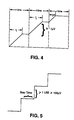
- the output waveform produced by ramp DAC 78 is illustrated in Fig. 4 for an increasing ramp waveform.
- the integrator 96 accumulates voltage during the time period that the pulse is at its high + 2.5 volt level for a period Tr. Tr may range from effectively 0 (when the LOAD value is at its smallest) to 10 milliseconds. These values give a range of duty cycle from 0% to 100%, and the effective overall ramping rate is therefore 477*Tr volts/seconds, with a resolution of 1 in 47,727, which is equal to 100 uV/sec or 1uV/10ms cycle.
- the ramp voltage waveform in Fig. 4 is to be compared with a conventional digitally generated staircase ramp function illustrated in Fig. 5.
- the conventional ramp staircase includes risers which have a minimum height of 1 LSB and a minimum step time which is fixed by the gating of the digital circuitry and can be very short.
- the resolution of the staircase function is therefore established by the resolution in the digital circuit producing the ramp staircase.
- Such a staircase ramp function can be digitally generated to a resolution of 1 in 16 bits using a 16 bit digital-to-analog converter. Such resolution is equivalent to 100uV. This resolution is 100 times worse than that achieved with Ramp Dac 78.
- a 16 bit digital to analog converter is relatively expensive and presently costs approximately $400.00.
- a 16 bit 9513 timer chip having five 9513 timers, on the other hand, costs about $22.00, and even when the cost of the switch 92, voltage reference sources 94 and integrator 96 are added in, the total cost for ramp DAC 78 is approximately $34.00.
- the remaining four timers on the chip may be used for other purposes, including other pulse width modulated DACs. When it is considered that apparatus 10 includes four such pulse width modulated DACs, it will be realized that the savings achieved in accordance with the present invention are dramatic.
- the pulse width modulated Ramp Dac 78 in accordance with the present invention is superior to conventional 16 bit DACs, since the present pulse width modulated DACs have a resolution of almost one in 23 bits and alternate ramps with steps, as opposed to alternating rises with steps.
- the integrator 96 smooths the transitions between the ramps and steps, which further adds to the overall smoothness of the synthesized ramp voltage waveform.
- Fig. 6 is a block diagram of ramp DAC 78, while Figs. 7-1 through 7-3 provide a wiring diagram thereof.
- PMT HVDAC 58 In addition to ramp DAC 78, PMT HVDAC 58, luminosity output DAC 70 and auxiliary analog output DAC 72 are also pulse width modulated DACs in accordance with the present invention.
- the LOAD and HOLD values are adjusted for the particular function so that, for example, PMT HVDAC 58 has a LOAD + HOLD constant of 1500, corresponding to the resolution of 1 volt in the range of 0-1500 volts.
- integrator 96 is omitted in each and in place thereof a low pass filter may be connected to attenuate any ac ripple in the output analog level.
- Potential DAC is a conventional 12 bit DAC which is programmable in response to the second digital control signal to output the second voltage waveform as a series of one or more constant voltages.
Landscapes
- Health & Medical Sciences (AREA)
- Biochemistry (AREA)
- General Physics & Mathematics (AREA)
- Life Sciences & Earth Sciences (AREA)
- Chemical & Material Sciences (AREA)
- Analytical Chemistry (AREA)
- Nuclear Medicine, Radiotherapy & Molecular Imaging (AREA)
- General Health & Medical Sciences (AREA)
- Physics & Mathematics (AREA)
- Immunology (AREA)
- Pathology (AREA)
- Investigating Or Analysing Materials By The Use Of Chemical Reactions (AREA)
- Manufacture Of Electron Tubes, Discharge Lamp Vessels, Lead-In Wires, And The Like (AREA)
- Control Of El Displays (AREA)
- Measuring Pulse, Heart Rate, Blood Pressure Or Blood Flow (AREA)
Claims (22)
- Vorrichtung zur Durchführung von Messungen elektrochemolumineszenter Phänome, umfassend Detektormittel (20) zum Detektieren elektromagnetischer Strahlung und zur Bereitstellung eines Signales, das indikativ für die Intensität der emittierten Strahlung ist;Zellenmittel (16) zum Halten eines Probefluids, das eine elektrochemolumineszente Komponente enthält;wobei das Detektormittel (20) derart angeordnet ist, daß es elektromagnetische Strahlung, die durch die elektrochemolumineszente Komponente in dem Probefluid emittiert worden ist, detektiert; und gekennzeichnet durchComputersteuermittel (12) zur Erzeugung einer vorherbestimmten Spannungswellenform, die mindestens eine ausgewählte Steigung aufweist;wobei das Computersteuermittel Mittel zur Erzeugung eines Steuersignals aufweist, das die ausgewählte Steigung darstellt und Mittel (78) zur Erzeugung der vorherbestimmten Spannungswellenform aufweist, die die ausgewählte Steigung als Antwort auf das Steuersignal haben; undArbeitselektrodenmittel (50) zum Anlegen elektrochemischer Energie auf das Probefluid als Antwort auf die vorherbestimmte Spannungswellenform und zur Aufnahme der vorherbestimmten Spannungswellenform, wobei die elektrochemische Energie derart ist, daß die elektrochemolumineszente Komponente in dem Probefluid dazu veranlaßt wird, wiederholt elektromagnetische Strahlung auszusenden.
- Vorrichtung gemäß Anspruch 1, wobei die Spannungswellenform eine Rampenspannungswellenform ist.
- Vorrichtung gemäß Anspruch 1, wobei das Computersteuermittel Mittel (78) zur Erzeugung einer Rampenspannungswellenform, wie die vorherbestimmte Spannungswellenform, umfaßt.
- Vorrichtung gemäß Anspruch 2, wobei das Steuersignal, das die ausgewählte Steigung darstellte, ein digitales Steuersignal ist und wobei das Mittel zur Erzeugung der vorherbestimmten Spannungswellenform Digital-Analogkonvertermittel (78) umfaßt, zur Erzeugung der Rampenspannungswellenform als Antwort auf das digitale Steuersignal; wobei das Digital-Analogkonvertermittel Pulsbreitenmodulationsmittel (90, 92, 94) umfaßt, zur Umwandlung der digitalen Steuersignale in ein puls-breitenmoduliertes Steuersignal; und Integratormittel (96) zur Erzeugung der Rampenspannungswellenform, deren Steigung bestimmt ist durch das pulsbreitenmodulierte Steuersignal, das durch das Pulsbreitenmodulationsmittel erzeugt wird.
- Vorrichtung gemäß Anspruch 4, wobei das Computersteuermittel Mittel zur Erzeugung eines zweiten digitalen Steuersignals umfaßt, das indikativ für eine zweite Spannungswellenform ist, das aus mindestens einer konstanten Spannung zusammengesetzt ist, wobei die Vorrichtung ferner ein zweites Digital-Analogkonvertermittel (80) zur Erzeugung der zweiten Spannungswellenform als Antwort auf das zweite digitale Steuersignal aufweist, und wobei das Arbeitselektrodenmittel (50) derart angeordnet ist, daß es auch die zweite Spannungswellenform empfängt und elektrochemische Energie auf das Probefluid als Antwort darauf anlegt.
- Vorrichtung gemäß Anspruch 4, wobei ferner Mittel zur Einführung eines Probefluids, das eine elektrochemolumineszente Komponente enthält, in das Zellenmittel vorgesehen sind.
- Vorrichtung gemäß Anspruch 4, wobei das Computersteuermittel ein programmierbares digitales Computermittel zur Erzeugung des digitalen Steuersignals aufweist.
- Vorrichtung gemäß Anspruch 4, wobei das Pulsbreitenmodulationsmittel programmierbare Timermittel (90) zur Bereitstellung einer ersten pulsbreitenmodulierten Pulsfolge als Antwort auf das digitale Steuersignal, das indikativ für die ausgewählte Steigung der Rampenspannungswellenform ist, umfaßt;wobei erste und zweite Spannungsquellen (92) obere bzw. untere Pulsamplituden definieren; undwobei Multiplexermittel (92) mit den ersten und zweiten Spannungsquellen (94) verbunden sind und diese ansprechend sind auf die erste pulsbreitenmodulierte Pulsfolge zur Erzeugung des pulsbreitenmodulierten Steuersignals als eine zweite pulsbreitenmodulierte Pulsfolge, die mindestens eine der oberen und unteren Pulsamplituden aufweist.
- Vorrichtung gemäß Anspruch 8, wobei das Computersteuermittel (12) derart betreibbar ist, daß es das digitale Steuersignal, das Ladewerte und Haltewerte aufweist, bereitstellt und wobei das programmierbare Timermittel ein 16 Bit Zählermittel aufweist, das ein 16 Bit Laderegister (100) und ein 16 Bit Halteregister (98) enthält zum Halten der Lade- bzw. Haltewerte, wobei der Arbeitszyklus jedes Pulses innerhalb der ersten pulsbreitenmodulierten Pulsfolge gleich dem Ladewert geteilt durch die Summe des Lade- und Haltewertes ist, wobei die Auflösung der Digital-Analogkonvertermittel größer als 16 Bit ist.
- Vorrichtung gemäß Anspruch 4, wobei das Detektormittel Lichtdetektormittel (20) zum Detektieren von Photonen der elektromagnetischen Strahlung, die durch die elektrochemolumineszente Komponente in dem Probefluid emittiert wurden, das einen Ausgangspuls als Antwort auf jedes detektierte Photon bereitstellt, und Zählermittel (68), die auf die Ausgangspulse ansprechen, um das Signal bereitzustellen, das indikativ für die Intensität der emittierten Strahlung ist, aufweist.
- Vorrichtung gemäß Anspruch 10, wobei das Signal, das Indikativ für die intensität der emittierten Strahlung ist, ein digitales Signal ist.
- Vorrichtung gemäß Anspruch 10, wobei das Lichtdetektormittel (20) ein Photomultiplikatorröhrenmittel umfaßt.
- Vorrichtung gemäß Anspruch 10, wobei das Zählermittel (68) ein erstes digitales Signal, das indikativ für eine Zählung einer ersten Bruchteilzahl der Ausgangspulse ist, und ein zweites digitales Signal, das indikativ für eine Zählung einer zweiten Bruchteilzahl der Ausgangspulse ist, bereitstellt.
- Vorrichtung gemäß Anspruch 13, wobei ferner ein Ausgangsdigital-Analogkonvertermittel (70) vorgesehen ist, zur Umwandlung eines ausgewählten Signals der ersten und zweiten Ausgangsdigitalsignale in analoge Form.
- Vorrichtung gemäß Anspruch 6, wobei die Mittel zur Einführung eines Probefluids in die Zellenmittel Fluidtransportmittel (34) zur Einführung einer Probe in das und aus dem Zellenmittel (16) umfaßt.
- Vorrichtung gemäß Anspruch 1, wobei das Computersteuermittel (12) Mittel zur Erzeugung einer gekrümmten Wellenform als die erstgenannte, vorherbestimmte Spannungswellenform umfaßt.
- Vorrichtung gemäß Anspruch 16, wobei die Mittel zur Erzeugung einer gekrümmten Wellenform Mittel zur Erzeugung einer sinusförmigen Wellenform umfassen.
- Vorrichtung gemäß Anspruch 3, wobei das Computersteuermittel (12) Mittel (80) zur Erzeugung einer zweiten vorherbestimmten Spannungswellenform und Mittel (82, 84) zur Kombination der Rampenspannungswellenform und der zweiten vorherbestimmten Spannungswellenform umfaßt.
- Vorrichtung gemäß Anspruch 1, wobei das Mittel zur Erzeugung eines Steuersignals Mittel zur Erzeugung eines digitalen Steuersignals umfaßt, das die ausgewählte Steigung darstellt.
- Vorrichtung gemäß Anspruch 19, wobei das Mittel zur Erzeugung der erstgenannten vorherbestimmten Spannungswellenform Mittel (90, 92, 94) umfaßt, zur Erzeugung einer Pulsfolge, die pulsbreitenmoduliert als Antwort auf das digitale Steuersignal ist, und Mittel (96) zum Integrieren der Pulsfolge vorgesehen sind, um die erstgenannte vorherbestimmte Spannungswellenform zu erzeugen.
- Vorrichtung gemäß Anspruch 1, wobei das Mittel zur Erzeugung eines Steuersignals, das die ausgewählte Steigung darstellt, Computermittel (24) zur Erzeugung eines digitalen Steuersignals umfaßt, das die mindestens eine ausgewählte Steigung darstellt; und wobei das Mittel zur Erzeugung der erstgenannten vorherbestimmten Spannungswellenform Mittel (78) zur Erzeugung der erstgenannten vorherbestimmten Spannungswellenform umfaßt, die die ausgewählte Steigung als Antwort auf das digitale Steuersignal aufweist.
- Vorrichtung gemäß Anspruch 21, wobei das Mittel zur Erzeugung der ersterwähnten vorherbestimmten Spannungswellenform Integratormittel (96) umfaßt, zur Erzeugung der erstgenannten vorherbestimmten Spannungswellenform als Antwort auf ein Steuereingangssignal, das dazu bereitgestellt wird, und das die ausgewählte Steigung der erstgenannten vorherbestimmten Spannungswellenform darstellt; und Mittel (90, 92, 94) zum Anlegen des Steuereingangssignals an das Integratormittel als Antwort auf die digitalen Steuersignale, so daß das Integratormittel die ersterwähnte vorbestimmte Spannungswellenform, die die vorherbestimmte Steigung aufweist, produziert.
Applications Claiming Priority (3)
| Application Number | Priority Date | Filing Date | Title |
|---|---|---|---|
| US07/267,234 US5061445A (en) | 1988-11-03 | 1988-11-03 | Apparatus for conducting measurements of electrochemiluminescent phenomena |
| US267234 | 1988-11-03 | ||
| PCT/US1989/004854 WO1990005411A1 (en) | 1988-11-03 | 1989-10-31 | Apparatus and method for conducting measurements of electroluminescent phenomena |
Publications (3)
| Publication Number | Publication Date |
|---|---|
| EP0441880A1 EP0441880A1 (de) | 1991-08-21 |
| EP0441880A4 EP0441880A4 (en) | 1992-11-25 |
| EP0441880B1 true EP0441880B1 (de) | 1996-09-25 |
Family
ID=23017898
Family Applications (1)
| Application Number | Title | Priority Date | Filing Date |
|---|---|---|---|
| EP89912913A Expired - Lifetime EP0441880B1 (de) | 1988-11-03 | 1989-10-31 | Gerät zur durchführung von messungen von elektrolumineszenz-phänomenen |
Country Status (12)
| Country | Link |
|---|---|
| US (1) | US5061445A (de) |
| EP (1) | EP0441880B1 (de) |
| JP (1) | JPH076912B2 (de) |
| KR (1) | KR900702650A (de) |
| AT (1) | ATE143497T1 (de) |
| AU (1) | AU637070B2 (de) |
| CA (1) | CA2002100C (de) |
| DE (1) | DE68927263T2 (de) |
| IL (1) | IL92165A (de) |
| MX (1) | MX170953B (de) |
| WO (1) | WO1990005411A1 (de) |
| ZA (1) | ZA898287B (de) |
Families Citing this family (58)
| Publication number | Priority date | Publication date | Assignee | Title |
|---|---|---|---|---|
| US6054296A (en) * | 1988-10-24 | 2000-04-25 | Symbicom Ab | 66 kDa antigen from Borrelia |
| US5147806A (en) * | 1988-04-29 | 1992-09-15 | Igen, Inc. | Method and apparatus for conducting electrochemiluminescence measurements |
| US6881589B1 (en) | 1987-04-30 | 2005-04-19 | Bioveris Corporation | Electrochemiluminescent localizable complexes for assay compositions |
| US5935779A (en) * | 1988-11-03 | 1999-08-10 | Igen International Inc. | Methods for improved particle electrochemiluminescence assay |
| US5779976A (en) * | 1988-11-03 | 1998-07-14 | Igen International, Inc. | Apparatus for improved luminescence assays |
| US5296191A (en) * | 1988-11-03 | 1994-03-22 | Igen, Inc. | Method and apparatus for conducting electrochemiluminescent measurements |
| US5962218A (en) * | 1988-11-03 | 1999-10-05 | Igen International Inc. | Methods and apparatus for improved luminescence assays |
| IL100867A (en) * | 1991-02-06 | 1995-12-08 | Igen Inc | Method and apparatus for improved luminescence assays |
| ZA92803B (en) | 1991-02-06 | 1992-11-25 | Igen Inc | Method and apparatus for magnetic microparticulate based luminescene asay including plurality of magnets |
| IL100866A (en) * | 1991-02-06 | 1995-10-31 | Igen Inc | Method and apparatus for magnetic microparticulate based luminescence assay including plurality of magnets |
| US5578498A (en) | 1991-05-22 | 1996-11-26 | Behringwerke Ag | Metal chelate containing compositions for use in chemiluminescent assays |
| US6251581B1 (en) * | 1991-05-22 | 2001-06-26 | Dade Behring Marburg Gmbh | Assay method utilizing induced luminescence |
| ATE184320T1 (de) * | 1991-07-10 | 1999-09-15 | Igen Int Inc | Verfahren für verbesserte lumineszenz-assays unter verwendung von teilchenkonzentration und chemilumineszenznachweis |
| ZA929351B (en) * | 1991-12-11 | 1993-06-04 | Igen Inc | Electrochemiluminescent label for DNA assays. |
| WO1994025853A1 (de) * | 1993-05-03 | 1994-11-10 | Boehringer Mannheim Gmbh | Elektrochemilumineszenzverfahren |
| US5466416A (en) * | 1993-05-14 | 1995-11-14 | Ghaed; Ali | Apparatus and methods for carrying out electrochemiluminescence test measurements |
| WO1996005501A1 (en) | 1993-05-14 | 1996-02-22 | Igen, Inc. | Apparatus and methods for carrying out electrochemiluminescence test measurements |
| JPH10504105A (ja) * | 1994-08-15 | 1998-04-14 | イゲン,インコーポレーテッド | 電気化学ルミネセンスの試験測定を実施する装置および方法 |
| US20010003647A1 (en) * | 1995-06-07 | 2001-06-14 | Ji Sun | Coreatant-including electrochemiluminescent compounds, methods, systems and kits utilizing same |
| US5610075A (en) * | 1995-01-17 | 1997-03-11 | Stahl-Rees; Marianne | Competitive electrochemiluminescence assays for endotoxins using a ruthenium label |
| AU2929602A (en) * | 1995-03-10 | 2002-05-23 | Meso Scale Technologies, Llc | Multi-array, multi-specific electrochemiluminescence testing |
| US6673533B1 (en) | 1995-03-10 | 2004-01-06 | Meso Scale Technologies, Llc. | Multi-array multi-specific electrochemiluminescence testing |
| US6207369B1 (en) * | 1995-03-10 | 2001-03-27 | Meso Scale Technologies, Llc | Multi-array, multi-specific electrochemiluminescence testing |
| JPH11502617A (ja) | 1995-03-10 | 1999-03-02 | メソ スケール テクノロジーズ,エルエルシー | 多重アレイの多重特異的な電気化学発光試験 |
| US6140045A (en) * | 1995-03-10 | 2000-10-31 | Meso Scale Technologies | Multi-array, multi-specific electrochemiluminescence testing |
| JPH08297813A (ja) * | 1995-04-27 | 1996-11-12 | Nec Corp | 磁気ヘッドスライダ及びその製造方法 |
| US5663728A (en) * | 1995-05-18 | 1997-09-02 | Hughes Aircraft Company | Digital-to-analog converted (DAC) and method that set waveform rise and fall times to produce an analog waveform that approximates a piecewise linear waveform to reduce spectral distortion |
| CA2223027A1 (en) | 1995-06-07 | 1996-12-19 | Igen, Inc. | Electrochemiluminescent enzyme immunoassay |
| US6099760A (en) * | 1995-06-07 | 2000-08-08 | Igen, Inc. | Hydrogen peroxide based ECL |
| WO1996041155A1 (en) * | 1995-06-07 | 1996-12-19 | Igen, Inc. | An improved electrochemiluminescence method |
| CA2276462C (en) | 1996-12-31 | 2007-06-12 | High Throughput Genomics, Inc. | Multiplexed molecular analysis system apparatus and method |
| US6200531B1 (en) * | 1998-05-11 | 2001-03-13 | Igen International, Inc. | Apparatus for carrying out electrochemiluminescence test measurements |
| US6780617B2 (en) | 2000-12-29 | 2004-08-24 | Chen & Chen, Llc | Sample processing device and method |
| US7799521B2 (en) * | 1998-06-24 | 2010-09-21 | Chen & Chen, Llc | Thermal cycling |
| JP4321738B2 (ja) | 1998-06-24 | 2009-08-26 | チェン アンド チェン エルエルシー | 液体試料試験システム |
| US7141436B2 (en) * | 1999-11-03 | 2006-11-28 | Science And Technology Corp. | Immunoassay and reagents and kits for performing the same |
| GB0103765D0 (en) * | 2001-02-15 | 2001-04-04 | Affitech As | Assay |
| CA2460192C (en) | 2001-09-11 | 2011-04-19 | Iquum, Inc. | Sample vessels |
| KR20050013592A (ko) * | 2002-06-20 | 2005-02-04 | 아이젠인터내셔널인코포레이티드 | 전기화학발광 유동 셀 및 유동 셀 성분 |
| US7000870B2 (en) * | 2002-11-07 | 2006-02-21 | Aerion Corporation | Laminar flow wing for transonic cruise |
| CA2515075C (en) | 2003-02-05 | 2012-10-02 | Iquum, Inc. | Sample processing |
| US7238536B1 (en) * | 2004-03-22 | 2007-07-03 | Florida State University Research Foundation, Inc. | Controlled transport through multiple reversible interaction point membranes |
| KR101026248B1 (ko) * | 2004-09-21 | 2011-03-31 | 페어차일드코리아반도체 주식회사 | 역률 보상 회로 |
| JP2008521007A (ja) * | 2004-11-17 | 2008-06-19 | バイオヴェリス コーポレイション | 電気化学発光測定法 |
| US20060275841A1 (en) * | 2004-12-20 | 2006-12-07 | Martin Blankfard | Assay method and apparatus with reduced sample matrix effects |
| JP5590796B2 (ja) | 2005-06-03 | 2014-09-17 | ボード・オブ・リージェンツ・オブ・ザ・ユニバーシティ・オブ・テキサス・システム | 電気化学および単一ファラデー電極による電気化学発光 |
| WO2007002580A2 (en) * | 2005-06-23 | 2007-01-04 | Bioveris Corporation | Diagnostic as say system with multi -well reagent container |
| US7402805B1 (en) | 2005-08-22 | 2008-07-22 | The United States Of America As Represented By The Secretary Of The Navy | Device for the in-situ measurement of acoustically stimulated bioluminescence |
| PT2271938E (pt) | 2008-04-11 | 2014-05-09 | Univ Texas | Método e aparelho de amplificação de quimiluminescênci electrogerada por nanopartículas |
| AU2009244904B2 (en) | 2008-05-08 | 2014-04-17 | Board Of Regents Of The University Of Texas System | Luminescent nanostructured materials for use in electrogenerated chemiluminescence |
| ITTO20100212A1 (it) * | 2010-03-19 | 2011-09-20 | Cyanagen S R L | "procedimento per la generazione e l'analisi di segnali di elettrochemiluminescenza e relativo sistema" |
| WO2012154272A1 (en) | 2011-02-25 | 2012-11-15 | Wellstat Diagnostics, Llc | Assays for detecting enzymatic activity |
| US9625465B2 (en) | 2012-05-15 | 2017-04-18 | Defined Diagnostics, Llc | Clinical diagnostic systems |
| US9213043B2 (en) | 2012-05-15 | 2015-12-15 | Wellstat Diagnostics, Llc | Clinical diagnostic system including instrument and cartridge |
| US9075042B2 (en) | 2012-05-15 | 2015-07-07 | Wellstat Diagnostics, Llc | Diagnostic systems and cartridges |
| JP6239243B2 (ja) | 2013-02-08 | 2017-11-29 | エフ.ホフマン−ラ ロシュ アーゲーF. Hoffmann−La Roche Aktiengesellschaft | 自動分析装置 |
| CN104297231A (zh) * | 2014-10-30 | 2015-01-21 | 中国科学院长春应用化学研究所 | 一种电化学发光光谱仪 |
| FI20175623A1 (en) * | 2017-06-29 | 2018-12-30 | Labmaster Oy | A method and devices for adaptive measuring of electrochemiluminescence |
Citations (1)
| Publication number | Priority date | Publication date | Assignee | Title |
|---|---|---|---|---|
| JPH01247962A (ja) * | 1988-03-29 | 1989-10-03 | Hisaka Works Ltd | ヒートポンプ |
Family Cites Families (21)
| Publication number | Priority date | Publication date | Assignee | Title |
|---|---|---|---|---|
| NL7001235A (de) * | 1970-01-29 | 1971-08-02 | ||
| US3868534A (en) * | 1972-11-29 | 1975-02-25 | Bell Canada Northern Electric | Electrochemiluminescent device having a mixed solvent |
| FR2247732A1 (de) * | 1973-10-16 | 1975-05-09 | Accumulateurs Fixes | |
| US3963928A (en) * | 1974-05-17 | 1976-06-15 | Thermo Electron Corporation | Multiple chamber chemiluminescent analyzer |
| US3984688A (en) * | 1975-04-21 | 1976-10-05 | Source Gas Analyzers, Inc. | Monitor for detection of chemiluminescent reactions |
| JPS5843621B2 (ja) * | 1975-07-18 | 1983-09-28 | トキコ株式会社 | 密閉型シリンダ装置 |
| US4204037A (en) * | 1978-04-04 | 1980-05-20 | Nasa | Method and automated apparatus for detecting coliform organisms |
| US4236895A (en) * | 1979-06-11 | 1980-12-02 | Meloy Laboratories, Inc. | Analytical apparatus and method employing purified ozone |
| US4280815A (en) * | 1979-06-18 | 1981-07-28 | Technicon Instruments Corporation | Electrochemiluminescent immunoassay and apparatus therefor |
| DE3013765A1 (de) * | 1980-04-10 | 1981-10-15 | Philips Patentverwaltung Gmbh, 2000 Hamburg | Detektroranordnung, insbesondere fuer die fluessigkeitschromatografie |
| US4303410A (en) * | 1980-11-03 | 1981-12-01 | The United States Of America As Represented By The Secretary Of The Navy | Light burst activity analyzer |
| DE3260566D1 (en) * | 1981-06-12 | 1984-09-20 | Tour & Andersson Ab | Arrangement in climatization systems |
| US4468638A (en) * | 1982-02-11 | 1984-08-28 | The Bendix Corporation | Linear sweep frequency modulator for FM/CW radio altimeter |
| US4634574A (en) * | 1983-01-31 | 1987-01-06 | Iowa State Research Foundation, Inc. | Apparatus for use in sulfide chemiluminescence detection |
| US5238808A (en) * | 1984-10-31 | 1993-08-24 | Igen, Inc. | Luminescent metal chelate labels and means for detection |
| US4721601A (en) * | 1984-11-23 | 1988-01-26 | Massachusetts Institute Of Technology | Molecule-based microelectronic devices |
| JPS61247962A (ja) * | 1985-04-26 | 1986-11-05 | Hamamatsu Photonics Kk | 細胞診断装置 |
| US4822564A (en) * | 1985-07-02 | 1989-04-18 | Sensors, Inc. | Chemiluminescent gas analyzer for measuring the oxides of nitrogen |
| US4689305A (en) * | 1986-03-24 | 1987-08-25 | The United States Of America As Represented By The Secretary Of The Navy | Solid-state photometer circuit |
| GB8630136D0 (en) * | 1986-12-17 | 1987-01-28 | Grand Metropolitan Innovation | Luminometer apparatus |
| JPH0678985B2 (ja) * | 1987-03-06 | 1994-10-05 | ティーディーケイ株式会社 | 電気化学的光学特性検出用電極および電気化学的光学特性検出方法 |
-
1988
- 1988-11-03 US US07/267,234 patent/US5061445A/en not_active Expired - Lifetime
-
1989
- 1989-10-31 ZA ZA898287A patent/ZA898287B/xx unknown
- 1989-10-31 AU AU46267/89A patent/AU637070B2/en not_active Ceased
- 1989-10-31 KR KR1019900701439A patent/KR900702650A/ko not_active Ceased
- 1989-10-31 AT AT89912913T patent/ATE143497T1/de not_active IP Right Cessation
- 1989-10-31 JP JP2500333A patent/JPH076912B2/ja not_active Expired - Lifetime
- 1989-10-31 WO PCT/US1989/004854 patent/WO1990005411A1/en not_active Ceased
- 1989-10-31 EP EP89912913A patent/EP0441880B1/de not_active Expired - Lifetime
- 1989-10-31 IL IL9216589A patent/IL92165A/en active IP Right Grant
- 1989-10-31 DE DE68927263T patent/DE68927263T2/de not_active Expired - Lifetime
- 1989-11-02 CA CA002002100A patent/CA2002100C/en not_active Expired - Lifetime
- 1989-11-03 MX MX018214A patent/MX170953B/es unknown
Patent Citations (1)
| Publication number | Priority date | Publication date | Assignee | Title |
|---|---|---|---|---|
| JPH01247962A (ja) * | 1988-03-29 | 1989-10-03 | Hisaka Works Ltd | ヒートポンプ |
Also Published As
| Publication number | Publication date |
|---|---|
| AU4626789A (en) | 1990-05-28 |
| ATE143497T1 (de) | 1996-10-15 |
| IL92165A (en) | 1994-06-24 |
| CA2002100C (en) | 1994-12-06 |
| ZA898287B (en) | 1990-07-25 |
| MX170953B (es) | 1993-09-22 |
| DE68927263D1 (de) | 1996-10-31 |
| EP0441880A4 (en) | 1992-11-25 |
| IL92165A0 (en) | 1990-07-12 |
| JPH04502207A (ja) | 1992-04-16 |
| KR900702650A (ko) | 1990-12-08 |
| DE68927263T2 (de) | 1997-02-20 |
| WO1990005411A1 (en) | 1990-05-17 |
| JPH076912B2 (ja) | 1995-01-30 |
| US5061445A (en) | 1991-10-29 |
| CA2002100A1 (en) | 1990-05-03 |
| EP0441880A1 (de) | 1991-08-21 |
| AU637070B2 (en) | 1993-05-20 |
Similar Documents
| Publication | Publication Date | Title |
|---|---|---|
| EP0441880B1 (de) | Gerät zur durchführung von messungen von elektrolumineszenz-phänomenen | |
| US5068088A (en) | Method and apparatus for conducting electrochemiluminescent measurements | |
| US5247243A (en) | Method and apparatus for conducting electrochemiluminescent measurements | |
| US5296191A (en) | Method and apparatus for conducting electrochemiluminescent measurements | |
| CN102940496A (zh) | 用于延长光学传感器使用寿命的系统和方法 | |
| US5945344A (en) | Electrochemiluminescence method | |
| US4404461A (en) | Method and apparatus for controlling an analytical furnace | |
| Piepmeier et al. | Line profiles emitted by Cu and Ca hollow cathode lamps pulsed to one ampere | |
| Green et al. | Phosphorimeters for analysis of decay profiles and real time monitoring of exponential decay and oxygen concentrations | |
| O'Haver et al. | A microcomputer-controlled background correction system for atomic spectrometry | |
| Fujiwara et al. | N2-laser induced two photon ionization spectrometry for vitamins with a simple DC detector | |
| Inaba et al. | Measurement of very weak light signals and spectra | |
| SU1288561A1 (ru) | Способ измерени атомной флуоресценции и устройство дл его осуществлени | |
| Gibson | Rapid reaction methods in biochemistry | |
| JPS60242344A (ja) | 発光体の残光特性測定装置 | |
| AU649220C (en) | Method and apparatus for conducting electrochemiluminescent measurements | |
| EP0384298B1 (de) | Vorrichtung zur Gasanalyse | |
| SU1497464A1 (ru) | Устройство дл возбуждени атомной флуоресценции | |
| EP0783681B1 (de) | Vorrichtung und verfahren zur durchführung von testmessungen zur elektrochemilumineszenz | |
| Andreoni et al. | Statistical analysis of the noise in fluorescence measurements by the sampling technique | |
| JPH06167450A (ja) | 化学発光分析装置 | |
| JPH06281580A (ja) | 発光分光分析装置 | |
| RU2172948C1 (ru) | Устройство для измерения концентрации кислорода в газообразных и жидких средах | |
| Decambox et al. | New spectrofluorometer with pulsed intensified photodiodes array for direct trace determination of actinides and lanthanides in solutions | |
| JPS61277064A (ja) | イムノアツセイ法 |
Legal Events
| Date | Code | Title | Description |
|---|---|---|---|
| PUAI | Public reference made under article 153(3) epc to a published international application that has entered the european phase |
Free format text: ORIGINAL CODE: 0009012 |
|
| 17P | Request for examination filed |
Effective date: 19910501 |
|
| AK | Designated contracting states |
Kind code of ref document: A1 Designated state(s): AT BE CH DE FR GB IT LI LU NL SE |
|
| A4 | Supplementary search report drawn up and despatched |
Effective date: 19921005 |
|
| AK | Designated contracting states |
Kind code of ref document: A4 Designated state(s): AT BE CH DE FR GB IT LI LU NL SE |
|
| 17Q | First examination report despatched |
Effective date: 19941011 |
|
| GRAH | Despatch of communication of intention to grant a patent |
Free format text: ORIGINAL CODE: EPIDOS IGRA |
|
| GRAH | Despatch of communication of intention to grant a patent |
Free format text: ORIGINAL CODE: EPIDOS IGRA |
|
| GRAA | (expected) grant |
Free format text: ORIGINAL CODE: 0009210 |
|
| AK | Designated contracting states |
Kind code of ref document: B1 Designated state(s): AT BE CH DE FR GB IT LI LU NL SE |
|
| REF | Corresponds to: |
Ref document number: 143497 Country of ref document: AT Date of ref document: 19961015 Kind code of ref document: T |
|
| REG | Reference to a national code |
Ref country code: CH Ref legal event code: NV Representative=s name: ISLER & PEDRAZZINI AG |
|
| ITF | It: translation for a ep patent filed | ||
| RAP2 | Party data changed (patent owner data changed or rights of a patent transferred) |
Owner name: IGEN, INC. |
|
| REF | Corresponds to: |
Ref document number: 68927263 Country of ref document: DE Date of ref document: 19961031 |
|
| ET | Fr: translation filed | ||
| NLT2 | Nl: modifications (of names), taken from the european patent patent bulletin |
Owner name: IGEN, INC. |
|
| PLBE | No opposition filed within time limit |
Free format text: ORIGINAL CODE: 0009261 |
|
| STAA | Information on the status of an ep patent application or granted ep patent |
Free format text: STATUS: NO OPPOSITION FILED WITHIN TIME LIMIT |
|
| 26N | No opposition filed | ||
| REG | Reference to a national code |
Ref country code: CH Ref legal event code: PFA Free format text: IGEN, INC. TRANSFER- IGEN INTERNATIONAL, INC. |
|
| NLS | Nl: assignments of ep-patents |
Owner name: IGEN INTERNATIONAL, INC A DELAWARE CORPORATION |
|
| REG | Reference to a national code |
Ref country code: FR Ref legal event code: TP |
|
| REG | Reference to a national code |
Ref country code: GB Ref legal event code: IF02 |
|
| REG | Reference to a national code |
Ref country code: GB Ref legal event code: 732E |
|
| REG | Reference to a national code |
Ref country code: CH Ref legal event code: PUE Owner name: BIOVERIS CORPORATION Free format text: IGEN INTERNATIONAL, INC.#16020 INDUSTRIAL DRIVE#GAITHERSBURG/MD 20877 (US) -TRANSFER TO- BIOVERIS CORPORATION#16020 INDUSTRIAL DRIVE#GAITHERSBURG, MD 20877 (US) |
|
| NLS | Nl: assignments of ep-patents |
Owner name: BIOVERIS CORPORATION |
|
| REG | Reference to a national code |
Ref country code: FR Ref legal event code: TP |
|
| REG | Reference to a national code |
Ref country code: CH Ref legal event code: PCAR Free format text: ISLER & PEDRAZZINI AG;POSTFACH 1772;8027 ZUERICH (CH) |
|
| PGFP | Annual fee paid to national office [announced via postgrant information from national office to epo] |
Ref country code: LU Payment date: 20071106 Year of fee payment: 19 Ref country code: NL Payment date: 20071024 Year of fee payment: 19 |
|
| PGFP | Annual fee paid to national office [announced via postgrant information from national office to epo] |
Ref country code: BE Payment date: 20071107 Year of fee payment: 19 Ref country code: SE Payment date: 20071029 Year of fee payment: 19 |
|
| PGFP | Annual fee paid to national office [announced via postgrant information from national office to epo] |
Ref country code: CH Payment date: 20081027 Year of fee payment: 20 Ref country code: DE Payment date: 20081201 Year of fee payment: 20 |
|
| PGFP | Annual fee paid to national office [announced via postgrant information from national office to epo] |
Ref country code: AT Payment date: 20081002 Year of fee payment: 20 |
|
| PGFP | Annual fee paid to national office [announced via postgrant information from national office to epo] |
Ref country code: IT Payment date: 20081030 Year of fee payment: 20 |
|
| BERE | Be: lapsed |
Owner name: *BIO VERIS CORP. Effective date: 20081031 |
|
| PGFP | Annual fee paid to national office [announced via postgrant information from national office to epo] |
Ref country code: FR Payment date: 20081018 Year of fee payment: 20 |
|
| PGFP | Annual fee paid to national office [announced via postgrant information from national office to epo] |
Ref country code: GB Payment date: 20081029 Year of fee payment: 20 |
|
| NLV4 | Nl: lapsed or anulled due to non-payment of the annual fee |
Effective date: 20090501 |
|
| EUG | Se: european patent has lapsed | ||
| PG25 | Lapsed in a contracting state [announced via postgrant information from national office to epo] |
Ref country code: NL Free format text: LAPSE BECAUSE OF NON-PAYMENT OF DUE FEES Effective date: 20090501 |
|
| PG25 | Lapsed in a contracting state [announced via postgrant information from national office to epo] |
Ref country code: BE Free format text: LAPSE BECAUSE OF NON-PAYMENT OF DUE FEES Effective date: 20081031 |
|
| REG | Reference to a national code |
Ref country code: CH Ref legal event code: PL |
|
| REG | Reference to a national code |
Ref country code: GB Ref legal event code: PE20 Expiry date: 20091030 |
|
| PG25 | Lapsed in a contracting state [announced via postgrant information from national office to epo] |
Ref country code: GB Free format text: LAPSE BECAUSE OF EXPIRATION OF PROTECTION Effective date: 20091030 |
|
| PG25 | Lapsed in a contracting state [announced via postgrant information from national office to epo] |
Ref country code: LU Free format text: LAPSE BECAUSE OF NON-PAYMENT OF DUE FEES Effective date: 20081031 |
|
| PG25 | Lapsed in a contracting state [announced via postgrant information from national office to epo] |
Ref country code: SE Free format text: LAPSE BECAUSE OF NON-PAYMENT OF DUE FEES Effective date: 20081101 |