EP0441306A2 - Arrangement de rayonnage - Google Patents
Arrangement de rayonnage Download PDFInfo
- Publication number
- EP0441306A2 EP0441306A2 EP91101488A EP91101488A EP0441306A2 EP 0441306 A2 EP0441306 A2 EP 0441306A2 EP 91101488 A EP91101488 A EP 91101488A EP 91101488 A EP91101488 A EP 91101488A EP 0441306 A2 EP0441306 A2 EP 0441306A2
- Authority
- EP
- European Patent Office
- Prior art keywords
- tubes
- shelf arrangement
- arrangement according
- shaped piece
- shaped
- Prior art date
- Legal status (The legal status is an assumption and is not a legal conclusion. Google has not performed a legal analysis and makes no representation as to the accuracy of the status listed.)
- Withdrawn
Links
- 230000000295 complement effect Effects 0.000 claims description 3
- 238000006073 displacement reaction Methods 0.000 description 2
- 238000012986 modification Methods 0.000 description 2
- 230000004048 modification Effects 0.000 description 2
- 230000007423 decrease Effects 0.000 description 1
- 238000011161 development Methods 0.000 description 1
- 230000018109 developmental process Effects 0.000 description 1
- 230000000694 effects Effects 0.000 description 1
- 238000002347 injection Methods 0.000 description 1
- 239000007924 injection Substances 0.000 description 1
- 239000000463 material Substances 0.000 description 1
Images


Classifications
-
- F—MECHANICAL ENGINEERING; LIGHTING; HEATING; WEAPONS; BLASTING
- F16—ENGINEERING ELEMENTS AND UNITS; GENERAL MEASURES FOR PRODUCING AND MAINTAINING EFFECTIVE FUNCTIONING OF MACHINES OR INSTALLATIONS; THERMAL INSULATION IN GENERAL
- F16B—DEVICES FOR FASTENING OR SECURING CONSTRUCTIONAL ELEMENTS OR MACHINE PARTS TOGETHER, e.g. NAILS, BOLTS, CIRCLIPS, CLAMPS, CLIPS OR WEDGES; JOINTS OR JOINTING
- F16B12/00—Jointing of furniture or the like, e.g. hidden from exterior
- F16B12/10—Jointing of furniture or the like, e.g. hidden from exterior using pegs, bolts, tenons, clamps, clips, or the like
- F16B12/12—Jointing of furniture or the like, e.g. hidden from exterior using pegs, bolts, tenons, clamps, clips, or the like for non-metal furniture parts, e.g. made of wood, of plastics
- F16B12/26—Jointing of furniture or the like, e.g. hidden from exterior using pegs, bolts, tenons, clamps, clips, or the like for non-metal furniture parts, e.g. made of wood, of plastics using snap-action elements
-
- A—HUMAN NECESSITIES
- A47—FURNITURE; DOMESTIC ARTICLES OR APPLIANCES; COFFEE MILLS; SPICE MILLS; SUCTION CLEANERS IN GENERAL
- A47B—TABLES; DESKS; OFFICE FURNITURE; CABINETS; DRAWERS; GENERAL DETAILS OF FURNITURE
- A47B47/00—Cabinets, racks or shelf units, characterised by features related to dismountability or building-up from elements
- A47B47/02—Cabinets, racks or shelf units, characterised by features related to dismountability or building-up from elements made of metal only
-
- A—HUMAN NECESSITIES
- A47—FURNITURE; DOMESTIC ARTICLES OR APPLIANCES; COFFEE MILLS; SPICE MILLS; SUCTION CLEANERS IN GENERAL
- A47B—TABLES; DESKS; OFFICE FURNITURE; CABINETS; DRAWERS; GENERAL DETAILS OF FURNITURE
- A47B47/00—Cabinets, racks or shelf units, characterised by features related to dismountability or building-up from elements
- A47B47/04—Cabinets, racks or shelf units, characterised by features related to dismountability or building-up from elements made mainly of wood or plastics
- A47B47/05—Cabinets, racks or shelf units, characterised by features related to dismountability or building-up from elements made mainly of wood or plastics with panels on a separate frame, e.g. a metal frame
Definitions
- the invention relates to a shelf arrangement with vertical support arrangements which are connected by parallel tubes located at the same height
- the vertical support arrangements are connected by parallel tubes, two parallel tubes, for example, extending at the same height between two support arrangements in the lower region of a shelf. Shelf elements, such as a cabinet segment, are then attached to these parallel tubes.
- this object is achieved by the measures specified in claim 1.
- the shelf arrangement is particularly advantageous for the shelf arrangement to be designed such that the mold cavities on the mutually facing sides of the tubes extend to below their central planes. This achieves a particularly good, form-fitting connection, especially when the mold cavities are at a distance from one another at their locations extending below the central plane of the pipes, which is greater than the distance between the pipes in the region of their central planes. In this case, the fitting snaps onto the pipes, i.e. there is a clamping effect.
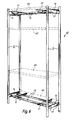
- Fig. 1 shows schematically a shelf arrangement 10 with two vertical support arrangements 11 and 12, which could also be referred to as ladders and have the cross struts 13 and 14, to which parallel tubes 15 are fastened by means of screws 17.
- Plastic fittings 21 are attached to these tubes according to the invention, the structure of which can be seen in more detail in FIGS. 2 to 5.
- the fittings 21 serve in the shelf 10 of FIG. 1 as a support for a - indicated by dashed lines - cabinet segment 18 with two wing doors 19, 20, which on the upper cross struts 13, 14th is fastened by means of the screws 17 provided there and the weight of which rests on the two shaped pieces 21 and is transferred from these to the pipes 15. Given the weight that such a cabinet segment 18 filled with objects, it is important that the weight is properly transferred from it to the tubes 15. The fittings 21 are used for this purpose.
- FIG. 2 shows a shaped piece 21 of this type in a side view and positively fastened on two tubes 15, FIG. 3 in a top view, FIG. 4 in section and FIG. 5 in a spatial representation.
- the shaped piece 21 has a flat bearing surface 25, which here e.g. serves as a support for the underside of the cabinet segment 18, which underside can be secured against lateral displacement by two pins 27, 28. These pins each engage in a corresponding bore in the cabinet element 18 and in a corresponding recess 29 or 30 of the fitting 21.
- the fitting 21 is approximately trough-shaped, i.e. it has a continuous wall 26, the upper edge of which forms the flat bearing surface 25, and this wall is closed at the bottom by a bottom 31.
- the shaped piece 21 is preferably designed as an injection molded part made of a suitable plastic.
- a central section 33 of the fitting 21 which has its smallest cross section in a central region 34 and whose cross section increases to the left and right of the region 34 in the two regions 35 and 36, namely up to two mold cavities 37 or 38, which are each complementary to the associated tube 15, as FIG. 2 clearly shows.
- the mold cavities 37 and 38 could also be designed to be complementary only in some areas.
- the center planes of the tubes 15 are designated 40 and 41.
- the two mold cavities 37 and 38 are now designed such that they extend on the mutually facing sides of the tubes 15 to a point 37 ′ and 38 ′, respectively, which is below the central plane 40 or the central plane 41. (The two middle planes 40 and 41 lie here on the same plane). Furthermore, the distance between the points 37 'and 38' is chosen to be greater than the distance a between the two tubes 15, ie when the shaped piece 21 is placed on the tubes 15, the shaped piece snaps onto these tubes.
- the mold cavities 37, 38 each extend over a little less than 180 ° of the circumference of the tubes 15, the size of this angle naturally being variable. They each extend to a point 37 ′′ or 38 ′′. From there, the cross section of the shaped piece 21 decreases towards the outside up to its left end 45 or its right end 46, as the drawings clearly show.
- the shaped piece 21, as is also clear from FIG. 4, has an upwardly open U-shaped profile with the two side walls 26 and the bottom 31, which delimit a mold cavity 50.
- the material cross section of the fitting 21 is adapted to the maximum load to be carried.
- a pin 51 or 52 is provided at both ends of the shaped piece 21, which extends from the bottom 31 upwards and in which the recess in question is formed.
- the top of the pins 51, 52 is flush with the support surface 25, so it is the same height as this.
- FIG. 6 shows a shelf 60, the support arrangements 11 and 12 of which are of the same design as in FIG. 1. The same or equivalent parts are therefore designated with the same reference numerals as there and are usually not described again.
- two parallel tubes 15 are screwed to the lower cross struts 13, 14 by means of screws 17, and likewise two parallel tubes 15 are screwed to the upper cross struts 13, 14 by means of screws 17, so that there is a stable basic system which is still can be stiffened by rear struts (not shown) if need be.
- Two shaped pieces 21 are arranged at a distance from each other both on the lower and on the upper tubes 15, which serve here, for example, as a support for a lower shelf 62 and an upper shelf 63. Furthermore, two further shelves 64 and 65 are suspended on the vertical support arrangements 11 and 12.
Landscapes
- Engineering & Computer Science (AREA)
- General Engineering & Computer Science (AREA)
- Mechanical Engineering (AREA)
- Life Sciences & Earth Sciences (AREA)
- Wood Science & Technology (AREA)
- Assembled Shelves (AREA)
Applications Claiming Priority (2)
| Application Number | Priority Date | Filing Date | Title |
|---|---|---|---|
| DE9001478U | 1990-02-09 | ||
| DE9001478 | 1990-02-09 |
Publications (2)
| Publication Number | Publication Date |
|---|---|
| EP0441306A2 true EP0441306A2 (fr) | 1991-08-14 |
| EP0441306A3 EP0441306A3 (en) | 1992-05-06 |
Family
ID=6850838
Family Applications (1)
| Application Number | Title | Priority Date | Filing Date |
|---|---|---|---|
| EP19910101488 Withdrawn EP0441306A3 (en) | 1990-02-09 | 1991-02-05 | Rack arrangement |
Country Status (2)
| Country | Link |
|---|---|
| EP (1) | EP0441306A3 (fr) |
| DE (1) | DE9101304U1 (fr) |
Cited By (1)
| Publication number | Priority date | Publication date | Assignee | Title |
|---|---|---|---|---|
| ITPN20090061A1 (it) * | 2009-10-23 | 2011-04-24 | Paolo Sonego | Sistema di elementi orizzontali per il supporto di elementi pensili. |
Family Cites Families (3)
| Publication number | Priority date | Publication date | Assignee | Title |
|---|---|---|---|---|
| BE473824A (fr) * | 1946-02-22 | |||
| US3054643A (en) * | 1960-07-18 | 1962-09-18 | Finkel Outdoor Prod | Chairs with snap-on slats and such slats |
| FR1274970A (fr) * | 1960-09-19 | 1961-11-03 | G O Lacroix Sa Des Ets | Meuble à pieds et notamment chaise |
-
1991
- 1991-02-05 EP EP19910101488 patent/EP0441306A3/de not_active Withdrawn
- 1991-02-06 DE DE9101304U patent/DE9101304U1/de not_active Expired - Lifetime
Cited By (1)
| Publication number | Priority date | Publication date | Assignee | Title |
|---|---|---|---|---|
| ITPN20090061A1 (it) * | 2009-10-23 | 2011-04-24 | Paolo Sonego | Sistema di elementi orizzontali per il supporto di elementi pensili. |
Also Published As
| Publication number | Publication date |
|---|---|
| EP0441306A3 (en) | 1992-05-06 |
| DE9101304U1 (de) | 1991-06-20 |
Similar Documents
| Publication | Publication Date | Title |
|---|---|---|
| DE69109836T2 (de) | Modulartiger Förderer. | |
| DE2642617C2 (fr) | ||
| DE2359541A1 (de) | Kettenfoerderer | |
| DE3822019C2 (de) | Schiebetürbeschlag | |
| DE29920996U1 (de) | Stelleinrichtung | |
| CH675060A5 (fr) | ||
| DE102005056625A1 (de) | Wand- oder Türelement | |
| DE2365225A1 (de) | Haengefoerderbahn | |
| EP0441306A2 (fr) | Arrangement de rayonnage | |
| DD204288A5 (de) | Federelement | |
| EP0514387A1 (fr) | Dispositif de stockage vertical, notamment pour vehicule. | |
| DE69410656T2 (de) | Wiegegerät, hauptsächlich zur Montage auf einem Fahrzeug | |
| DE2415572A1 (de) | Moebel-, insbesondere tischgestell | |
| DE4204861C1 (en) | Guide rail fastened to floor - has special curved fittings to go round corners in corridors or factory premises | |
| DE4336188C2 (de) | Schaltschrank mit Rahmengestell und Türelementen | |
| DE8906251U1 (de) | Tisch, insbesondere Bürotisch | |
| DE3134743C2 (de) | Aufgesetztes Scharnier | |
| DE1298044B (de) | Bandfoerderer | |
| DE7437812U (de) | Zusammenklappbarer wagen oder serviertisch | |
| DE2840090A1 (de) | Fuehrungsvorrichtung fuer schuebe | |
| DE9113154U1 (de) | Tisch mit einer Verbindungsanordnung | |
| DE9417955U1 (de) | Krangabel | |
| EP0256211A2 (fr) | Dispositif de support pour le cylindre de plastification d'une unité d'injection de matière plastique | |
| DE29722358U1 (de) | Modular aufgebautes Gestell | |
| DE19748397A1 (de) | Montageklotz für Fenster |
Legal Events
| Date | Code | Title | Description |
|---|---|---|---|
| PUAI | Public reference made under article 153(3) epc to a published international application that has entered the european phase |
Free format text: ORIGINAL CODE: 0009012 |
|
| AK | Designated contracting states |
Kind code of ref document: A2 Designated state(s): BE CH DE ES FR GB IT LI NL |
|
| PUAL | Search report despatched |
Free format text: ORIGINAL CODE: 0009013 |
|
| AK | Designated contracting states |
Kind code of ref document: A3 Designated state(s): BE CH DE ES FR GB IT LI NL |
|
| 17P | Request for examination filed |
Effective date: 19920413 |
|
| 17Q | First examination report despatched |
Effective date: 19940526 |
|
| STAA | Information on the status of an ep patent application or granted ep patent |
Free format text: STATUS: THE APPLICATION IS DEEMED TO BE WITHDRAWN |
|
| 18D | Application deemed to be withdrawn |
Effective date: 19940901 |