EP0441162B1 - Tiroir - Google Patents
Tiroir Download PDFInfo
- Publication number
- EP0441162B1 EP0441162B1 EP91100721A EP91100721A EP0441162B1 EP 0441162 B1 EP0441162 B1 EP 0441162B1 EP 91100721 A EP91100721 A EP 91100721A EP 91100721 A EP91100721 A EP 91100721A EP 0441162 B1 EP0441162 B1 EP 0441162B1
- Authority
- EP
- European Patent Office
- Prior art keywords
- side members
- rear wall
- edge region
- region
- members
- Prior art date
- Legal status (The legal status is an assumption and is not a legal conclusion. Google has not performed a legal analysis and makes no representation as to the accuracy of the status listed.)
- Expired - Lifetime
Links
Images


Classifications
-
- A—HUMAN NECESSITIES
- A47—FURNITURE; DOMESTIC ARTICLES OR APPLIANCES; COFFEE MILLS; SPICE MILLS; SUCTION CLEANERS IN GENERAL
- A47B—TABLES; DESKS; OFFICE FURNITURE; CABINETS; DRAWERS; GENERAL DETAILS OF FURNITURE
- A47B88/00—Drawers for tables, cabinets or like furniture; Guides for drawers
- A47B88/90—Constructional details of drawers
- A47B88/941—Drawers being constructed from two or more parts
-
- A—HUMAN NECESSITIES
- A47—FURNITURE; DOMESTIC ARTICLES OR APPLIANCES; COFFEE MILLS; SPICE MILLS; SUCTION CLEANERS IN GENERAL
- A47B—TABLES; DESKS; OFFICE FURNITURE; CABINETS; DRAWERS; GENERAL DETAILS OF FURNITURE
- A47B2210/00—General construction of drawers, guides and guide devices
- A47B2210/02—Drawers with hollow lateral walls in two parts
-
- A—HUMAN NECESSITIES
- A47—FURNITURE; DOMESTIC ARTICLES OR APPLIANCES; COFFEE MILLS; SPICE MILLS; SUCTION CLEANERS IN GENERAL
- A47B—TABLES; DESKS; OFFICE FURNITURE; CABINETS; DRAWERS; GENERAL DETAILS OF FURNITURE
- A47B88/00—Drawers for tables, cabinets or like furniture; Guides for drawers
- A47B88/90—Constructional details of drawers
- A47B88/919—Accessories or additional elements for drawers, e.g. drawer lighting
- A47B88/931—Rails or rods mounted above the drawer walls, e.g. for stabilisation of the drawer or for suspension of the content
Definitions
- the present innovation relates to a drawer with side frames made of plastic or metal profiles, a bottom engaging in receiving grooves in the lower edge region of the side frames and a rear wall connected to the side frames, in which the rear wall consists of a plastic or a metal profile, and that the rear wall, like the side frames, is provided in the lower edge region with a receiving groove in which the bottom engages on the rear.
- Drawers of the aforementioned type are known from US-A-3926491.
- the present innovation is based on the task of further developing a drawer of the generic type in such a way that an improved connection between the side frames and the rear wall is made possible.
- this object is achieved in that the side frames in the upper edge region are provided with a screw-in channel running in the longitudinal direction of the frame, in that the side frames in the connection region to the rear wall are miter-cut, such that the rear wall in the upper edge region merges over the screw channel of the side frames has downwardly extending leg which is penetrated by fastening screws screwed into the screw channels.
- a drawer designed in this way offers an improved connection option between the side frames and the rear wall due to the miter cut.
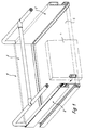
- the drawer shown in Fig. 1, generally designated by the reference numeral 1, is equipped with side frames 2, which consist of plastic or metal profiles. Furthermore, the drawer 1 has a rear wall 3 as well as a base 5 and a front plate 4, which is only indicated in the drawing.
- the side frames 2, the cross section of which is clearly shown again in FIG. 2, are in their lower edge region provided with a receiving groove 6, in which the bottom 5 engages.
- speargun webs 7 are formed in the longitudinal direction of the side frames 2, which engage in corresponding grooves 8 of the base 5, whereby this base 5 is fixed within the receiving grooves 6.
- Fig. 2 also makes it clear that the side frames 2 are equipped in their upper edge region with screw channels 12 extending in the longitudinal direction of the side frames 2.
- FIG. 3 shows the cross section of the rear wall 3 already mentioned.
- a receiving groove 6 for the bottom 5 is also provided in the lower edge region.
- the already mentioned harpoon bridge 7 is formed in the central area of this receiving groove 6, the already mentioned harpoon bridge 7 is formed.
- a holding groove 10 for a seal 11 resting on the upper side of the bottom 5, so that the bottom 11 also seals the rear wall in the rear area 3 is connected.
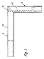
- the rear wall 3 has an after legs 13 below. This leg 13 extends beyond the screw channels 12 of the side frames 2 downwards. Fig. 4 makes it clear that the side frames 2 and the rear wall 3 are mitred in the connection area.
- fastening screws 14 are provided which pass through the downward leg 13 of the rear wall 3, are supported there and are screwed with their threaded area into the screw-in channels 12 of the side frames 2.
- the side frames 2 are provided in their upper edge region with a profile groove 15 which extends obliquely upwards and opens outwards.
- a profile web 16 of an attachment profile 17 can be inserted into each of these profile grooves 15, as a result of which the attachment profile 17 is positively fixed on the upper side of the respective side frame 2.
- the attachment profiles 17 can be additionally fixed by screws 18 (only indicated in FIG. 2).
- the rear wall 3 can be equipped in the same way with a profile groove 15 for receiving an attachment profile 17.
- the side frames 2 and the rear wall 3 according to FIGS. 5 and 6 differ from the previously illustrated embodiment in that the upper edge region is rounded. Irrespective of this, a screw-in channel 12 is also provided in the upper edge area of each side frame 2 and a leg 13 directed downward, which extends downward beyond the screw-in channels 12 of the side frames 2 and serves to support fastening screws, which serves in the screw-in channels 12 of the side frames 2 cut miter in the connection area as well as the rear wall 3.
- a receiving groove 6 is again provided for a drawer bottom. The same applies to the rear wall 3.
- the receiving grooves 6 are delimited by lip-like legs 19, which can be designed as resilient legs, in particular in the production of the side frames and the rear wall, and can thus be pressed tightly onto a bottom pushed into the receiving groove 6.
- FIG. 5 shows that harpoon webs 7 can also be provided in this embodiment for even better fixing of a floor in the area of the receiving grooves 6.
Claims (6)
- Tiroir pourvu de châssis latéraux constitués de profilés en matière plastique ou en métal, d'un fond s'engageant dans des rainures de réception dans la partie inférieure du bord des châssis latéraux, et d'une paroi arrière reliée aux châssis latéraux, ainsi que d'un parement frontal, dans lequel la paroi arrière (3) est constituée d'un profilé en matière plastique ou en métal, et la paroi arrière (3) est pourvue, tout comme les châssis latéraux (2), dans la partie inférieure du bord, d'une rainure de réception (6), dans laquelle le fond (5) s'engage par l'arrière,
caractérisé en ce que les châssis latéraux (2) sont pourvus, dans la partie supérieure du bord, d'un canal taraudé (12) s'étendant dans la direction longitudinale des châssis, en ce que, dans le secteur d'assemblage avec la paroi arrière (3), les châssis latéraux (2) sont coupés de biais comme celle-ci, en ce que la paroi arrière (3), présente, dans la partie supérieure du bord, une branche (13) s'étendant vers le bas, au-dessus du canal taraudé (12) des châssis latéraux (2), ladite branche étant traversée par des vis de fixation (14) vissées dans les canaux taraudés (12). - Tiroir selon la revendication 1, caractérisé en ce qu'un joint d'étanchéité (11) est prévu, dans la partie du flanc supérieur (9) respectivement des rainures de réception des châssis latéraux (2) et de la paroi arrière (3), ledit joint étant inséré dans une rainure de maintien (10) et prenant appui sur le fond (5).
- Tiroir selon la revendication 1 ou 2, caractérisé en ce que des retours (7) en forme de harpons, continus, venant en prise dans des rainures (8) correspondantes du fond (5), sont disposés dans le secteur médian des rainures de réception (6) des châssis latéraux (2) et de la paroi arrière (3).
- Tiroir selon la revendication 1, caractérisé en ce que les rainures de réception (6) sont délimitées par des branches (19) notamment élastiques, en forme de lèvres, dans leur partie supérieure recouvrant le fond (5).
- Tiroir selon l'une quelconque ou plusieurs des revendications 1 à 4, caractérisé en ce qu'au moins les châssis latéraux (2) sont pourvus dans la partie supérieure du bord, de rainures profilées (15) orientées de biais vers l'extérieur, dans lesquelles s'engagent des branches profilées (16) de profilés rapportés (17) placés sur les châssis latéraux (2), conformées de manière correspondante.
- Tiroir selon la revendication 5, caractérisé en ce que les profilés rapportés (17) sont assemblés aux châssis latéraux (2) par des vis (18).
Applications Claiming Priority (2)
| Application Number | Priority Date | Filing Date | Title |
|---|---|---|---|
| DE9001485U | 1990-02-09 | ||
| DE9001485U DE9001485U1 (fr) | 1990-02-09 | 1990-02-09 |
Publications (3)
| Publication Number | Publication Date |
|---|---|
| EP0441162A2 EP0441162A2 (fr) | 1991-08-14 |
| EP0441162A3 EP0441162A3 (en) | 1992-11-19 |
| EP0441162B1 true EP0441162B1 (fr) | 1994-09-28 |
Family
ID=6850844
Family Applications (1)
| Application Number | Title | Priority Date | Filing Date |
|---|---|---|---|
| EP91100721A Expired - Lifetime EP0441162B1 (fr) | 1990-02-09 | 1991-01-22 | Tiroir |
Country Status (2)
| Country | Link |
|---|---|
| EP (1) | EP0441162B1 (fr) |
| DE (1) | DE9001485U1 (fr) |
Cited By (1)
| Publication number | Priority date | Publication date | Assignee | Title |
|---|---|---|---|---|
| DE202013010931U1 (de) | 2012-12-12 | 2014-03-27 | Julius Blum Gmbh | Verbindung zweier Teile |
Families Citing this family (6)
| Publication number | Priority date | Publication date | Assignee | Title |
|---|---|---|---|---|
| DE4011815A1 (de) * | 1990-04-12 | 1991-10-17 | Lautenschlaeger Kg Karl | Metall-zarge fuer schubladen-waende |
| AT400999B (de) * | 1993-02-10 | 1996-05-28 | Blum Gmbh Julius | Schubladenbausatz |
| DE4319716A1 (de) * | 1993-06-02 | 1994-12-08 | Lautenschlaeger Mepla Werke | Befestigungsanordnung für Schubladen-Böden |
| DE20015595U1 (de) * | 2000-09-08 | 2000-11-30 | Jahn Ulrich | Zarge für Schubladen |
| WO2011085710A1 (fr) | 2010-01-13 | 2011-07-21 | Fehre Design Gmbh | Tiroir, démontable et empilable |
| DE202009012917U1 (de) | 2009-09-26 | 2011-02-10 | Fehre, Jürgen | Schubkasten |
Family Cites Families (3)
| Publication number | Priority date | Publication date | Assignee | Title |
|---|---|---|---|---|
| DE1199453B (de) * | 1961-11-16 | 1965-08-26 | Karl Schock | Zarge od. dgl. aus Kunststoff, insbesondere fuer kastenfoermige Moebel, Schubladen od. ae. |
| US3926491A (en) * | 1974-04-17 | 1975-12-16 | Philip A Greer | Knock-down drawer assembly |
| DE3001706A1 (de) * | 1980-01-18 | 1981-07-23 | Alno-Möbelwerke GmbH & Co KG, 7798 Pfullendorf | Eckverbindung fuer seiten- und querteile von schukastenzargen |
-
1990
- 1990-02-09 DE DE9001485U patent/DE9001485U1/de not_active Expired - Lifetime
-
1991
- 1991-01-22 EP EP91100721A patent/EP0441162B1/fr not_active Expired - Lifetime
Cited By (1)
| Publication number | Priority date | Publication date | Assignee | Title |
|---|---|---|---|---|
| DE202013010931U1 (de) | 2012-12-12 | 2014-03-27 | Julius Blum Gmbh | Verbindung zweier Teile |
Also Published As
| Publication number | Publication date |
|---|---|
| EP0441162A2 (fr) | 1991-08-14 |
| DE9001485U1 (fr) | 1990-04-12 |
| EP0441162A3 (en) | 1992-11-19 |
Similar Documents
| Publication | Publication Date | Title |
|---|---|---|
| EP0200760B1 (fr) | Barre profilee pour le serrage des plaques, surtout les plaques en verre, pour des vitrines, distributeurs de vente, mobilier d'exposition et objets semblables | |
| EP0491762B1 (fr) | Table | |
| EP2479365A1 (fr) | Rail de guidage pour portes coulissantes ou repliables en accordéon | |
| DE4336187C2 (de) | Rahmenschenkel für ein Rahmengestell eines Schaltschrankes | |
| DE102015112563A1 (de) | Verbindungsanordnung zum Verbinden eines Pfostens an einem Rahmenprofil eines Fensters oder einer Türe aus Kunststoff | |
| EP0441162B1 (fr) | Tiroir | |
| DE1960704A1 (de) | Tuerrahmen | |
| DE2244055C3 (de) | Handlauf für Treppengeländer | |
| DE7921206U1 (de) | Fertigwand aus vorgefertigten moduleinheiten | |
| DE4242589A1 (en) | Frame for switch cubicle door panel - has frame of irregular section with edge supporting panel and cover strip to hold panel in place | |
| EP0663509A2 (fr) | Connecteur pour dormant | |
| DE6929081U (de) | Rahmen mit gebrungseckenverbindung. | |
| DE19900548A1 (de) | Strangpreßprofil als Eckverbindung für Behälter von Nutzfahrzeugen | |
| DE2654590C2 (de) | Gestell für elektrische Schaltanlagen | |
| DE69919571T2 (de) | Einbau von fenstern | |
| DE60202279T2 (de) | Rahmen zum festhalten einer plattenförmigen tafel | |
| DE19931039C2 (de) | Einrichtung zur Befestigung eines Profils | |
| EP0769259B1 (fr) | Joint d'angle | |
| DE10347882B3 (de) | Bettgestell | |
| DE2821101A1 (de) | Moebel-auszugfuehrung | |
| DE1937380C (de) | Gehrungseckenverbindung fur Rahmen und Gestelle | |
| DE7540299U (de) | Randleistenbeschlag fuer ganzglastueren oder -waende | |
| DE2243126C3 (de) | Rahmenartiges Bauteil aus Blech für einen Schrank o JgI | |
| EP0951113A2 (fr) | Boíte de forme rectangulaire pour loger des composants électriques ou électroniques | |
| DE19651466A1 (de) | Möbelsystem |
Legal Events
| Date | Code | Title | Description |
|---|---|---|---|
| PUAI | Public reference made under article 153(3) epc to a published international application that has entered the european phase |
Free format text: ORIGINAL CODE: 0009012 |
|
| AK | Designated contracting states |
Kind code of ref document: A2 Designated state(s): BE FR GB LU NL |
|
| PUAL | Search report despatched |
Free format text: ORIGINAL CODE: 0009013 |
|
| AK | Designated contracting states |
Kind code of ref document: A3 Designated state(s): BE FR GB LU NL |
|
| 17P | Request for examination filed |
Effective date: 19921110 |
|
| 17Q | First examination report despatched |
Effective date: 19931229 |
|
| GRAA | (expected) grant |
Free format text: ORIGINAL CODE: 0009210 |
|
| AK | Designated contracting states |
Kind code of ref document: B1 Designated state(s): BE FR GB LU NL |
|
| GBT | Gb: translation of ep patent filed (gb section 77(6)(a)/1977) |
Effective date: 19941019 |
|
| ET | Fr: translation filed | ||
| PLBE | No opposition filed within time limit |
Free format text: ORIGINAL CODE: 0009261 |
|
| STAA | Information on the status of an ep patent application or granted ep patent |
Free format text: STATUS: NO OPPOSITION FILED WITHIN TIME LIMIT |
|
| 26N | No opposition filed | ||
| PGFP | Annual fee paid to national office [announced via postgrant information from national office to epo] |
Ref country code: GB Payment date: 20000110 Year of fee payment: 10 |
|
| PGFP | Annual fee paid to national office [announced via postgrant information from national office to epo] |
Ref country code: FR Payment date: 20000118 Year of fee payment: 10 |
|
| PGFP | Annual fee paid to national office [announced via postgrant information from national office to epo] |
Ref country code: LU Payment date: 20000121 Year of fee payment: 10 Ref country code: BE Payment date: 20000121 Year of fee payment: 10 |
|
| PGFP | Annual fee paid to national office [announced via postgrant information from national office to epo] |
Ref country code: NL Payment date: 20000125 Year of fee payment: 10 |
|
| PG25 | Lapsed in a contracting state [announced via postgrant information from national office to epo] |
Ref country code: LU Free format text: LAPSE BECAUSE OF NON-PAYMENT OF DUE FEES Effective date: 20010122 Ref country code: GB Free format text: LAPSE BECAUSE OF NON-PAYMENT OF DUE FEES Effective date: 20010122 |
|
| PG25 | Lapsed in a contracting state [announced via postgrant information from national office to epo] |
Ref country code: BE Free format text: LAPSE BECAUSE OF NON-PAYMENT OF DUE FEES Effective date: 20010131 |
|
| BERE | Be: lapsed |
Owner name: SCHUCO INTERNATIONAL K.G. Effective date: 20010131 |
|
| PG25 | Lapsed in a contracting state [announced via postgrant information from national office to epo] |
Ref country code: NL Free format text: LAPSE BECAUSE OF NON-PAYMENT OF DUE FEES Effective date: 20010801 |
|
| GBPC | Gb: european patent ceased through non-payment of renewal fee |
Effective date: 20010122 |
|
| PG25 | Lapsed in a contracting state [announced via postgrant information from national office to epo] |
Ref country code: FR Free format text: LAPSE BECAUSE OF NON-PAYMENT OF DUE FEES Effective date: 20010928 |
|
| NLV4 | Nl: lapsed or anulled due to non-payment of the annual fee |
Effective date: 20010801 |
|
| REG | Reference to a national code |
Ref country code: FR Ref legal event code: ST |