EP0441162B1 - Drawer - Google Patents
Drawer Download PDFInfo
- Publication number
- EP0441162B1 EP0441162B1 EP91100721A EP91100721A EP0441162B1 EP 0441162 B1 EP0441162 B1 EP 0441162B1 EP 91100721 A EP91100721 A EP 91100721A EP 91100721 A EP91100721 A EP 91100721A EP 0441162 B1 EP0441162 B1 EP 0441162B1
- Authority
- EP
- European Patent Office
- Prior art keywords
- side members
- rear wall
- edge region
- region
- members
- Prior art date
- Legal status (The legal status is an assumption and is not a legal conclusion. Google has not performed a legal analysis and makes no representation as to the accuracy of the status listed.)
- Expired - Lifetime
Links
Images


Classifications
-
- A—HUMAN NECESSITIES
- A47—FURNITURE; DOMESTIC ARTICLES OR APPLIANCES; COFFEE MILLS; SPICE MILLS; SUCTION CLEANERS IN GENERAL
- A47B—TABLES; DESKS; OFFICE FURNITURE; CABINETS; DRAWERS; GENERAL DETAILS OF FURNITURE
- A47B88/00—Drawers for tables, cabinets or like furniture; Guides for drawers
- A47B88/90—Constructional details of drawers
- A47B88/941—Drawers being constructed from two or more parts
-
- A—HUMAN NECESSITIES
- A47—FURNITURE; DOMESTIC ARTICLES OR APPLIANCES; COFFEE MILLS; SPICE MILLS; SUCTION CLEANERS IN GENERAL
- A47B—TABLES; DESKS; OFFICE FURNITURE; CABINETS; DRAWERS; GENERAL DETAILS OF FURNITURE
- A47B2210/00—General construction of drawers, guides and guide devices
- A47B2210/02—Drawers with hollow lateral walls in two parts
-
- A—HUMAN NECESSITIES
- A47—FURNITURE; DOMESTIC ARTICLES OR APPLIANCES; COFFEE MILLS; SPICE MILLS; SUCTION CLEANERS IN GENERAL
- A47B—TABLES; DESKS; OFFICE FURNITURE; CABINETS; DRAWERS; GENERAL DETAILS OF FURNITURE
- A47B88/00—Drawers for tables, cabinets or like furniture; Guides for drawers
- A47B88/90—Constructional details of drawers
- A47B88/919—Accessories or additional elements for drawers, e.g. drawer lighting
- A47B88/931—Rails or rods mounted above the drawer walls, e.g. for stabilisation of the drawer or for suspension of the content
Definitions
- the present innovation relates to a drawer with side frames made of plastic or metal profiles, a bottom engaging in receiving grooves in the lower edge region of the side frames and a rear wall connected to the side frames, in which the rear wall consists of a plastic or a metal profile, and that the rear wall, like the side frames, is provided in the lower edge region with a receiving groove in which the bottom engages on the rear.
- Drawers of the aforementioned type are known from US-A-3926491.
- the present innovation is based on the task of further developing a drawer of the generic type in such a way that an improved connection between the side frames and the rear wall is made possible.
- this object is achieved in that the side frames in the upper edge region are provided with a screw-in channel running in the longitudinal direction of the frame, in that the side frames in the connection region to the rear wall are miter-cut, such that the rear wall in the upper edge region merges over the screw channel of the side frames has downwardly extending leg which is penetrated by fastening screws screwed into the screw channels.
- a drawer designed in this way offers an improved connection option between the side frames and the rear wall due to the miter cut.
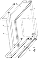
- the drawer shown in Fig. 1, generally designated by the reference numeral 1, is equipped with side frames 2, which consist of plastic or metal profiles. Furthermore, the drawer 1 has a rear wall 3 as well as a base 5 and a front plate 4, which is only indicated in the drawing.
- the side frames 2, the cross section of which is clearly shown again in FIG. 2, are in their lower edge region provided with a receiving groove 6, in which the bottom 5 engages.
- speargun webs 7 are formed in the longitudinal direction of the side frames 2, which engage in corresponding grooves 8 of the base 5, whereby this base 5 is fixed within the receiving grooves 6.
- Fig. 2 also makes it clear that the side frames 2 are equipped in their upper edge region with screw channels 12 extending in the longitudinal direction of the side frames 2.
- FIG. 3 shows the cross section of the rear wall 3 already mentioned.
- a receiving groove 6 for the bottom 5 is also provided in the lower edge region.
- the already mentioned harpoon bridge 7 is formed in the central area of this receiving groove 6, the already mentioned harpoon bridge 7 is formed.
- a holding groove 10 for a seal 11 resting on the upper side of the bottom 5, so that the bottom 11 also seals the rear wall in the rear area 3 is connected.
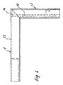
- the rear wall 3 has an after legs 13 below. This leg 13 extends beyond the screw channels 12 of the side frames 2 downwards. Fig. 4 makes it clear that the side frames 2 and the rear wall 3 are mitred in the connection area.
- fastening screws 14 are provided which pass through the downward leg 13 of the rear wall 3, are supported there and are screwed with their threaded area into the screw-in channels 12 of the side frames 2.
- the side frames 2 are provided in their upper edge region with a profile groove 15 which extends obliquely upwards and opens outwards.
- a profile web 16 of an attachment profile 17 can be inserted into each of these profile grooves 15, as a result of which the attachment profile 17 is positively fixed on the upper side of the respective side frame 2.
- the attachment profiles 17 can be additionally fixed by screws 18 (only indicated in FIG. 2).
- the rear wall 3 can be equipped in the same way with a profile groove 15 for receiving an attachment profile 17.
- the side frames 2 and the rear wall 3 according to FIGS. 5 and 6 differ from the previously illustrated embodiment in that the upper edge region is rounded. Irrespective of this, a screw-in channel 12 is also provided in the upper edge area of each side frame 2 and a leg 13 directed downward, which extends downward beyond the screw-in channels 12 of the side frames 2 and serves to support fastening screws, which serves in the screw-in channels 12 of the side frames 2 cut miter in the connection area as well as the rear wall 3.
- a receiving groove 6 is again provided for a drawer bottom. The same applies to the rear wall 3.
- the receiving grooves 6 are delimited by lip-like legs 19, which can be designed as resilient legs, in particular in the production of the side frames and the rear wall, and can thus be pressed tightly onto a bottom pushed into the receiving groove 6.
- FIG. 5 shows that harpoon webs 7 can also be provided in this embodiment for even better fixing of a floor in the area of the receiving grooves 6.
Description
Die vorliegende Neuerung betrifft einen Schubkasten mit aus Kunststoff- oder Metall-Profilen bestehenden Seitenzargen, einem in Aufnahmenuten im unteren Randbereich der Seitenzargen eingreifenden Boden und einer mit den Seitenzargen verbundenen Rückwand, bei dem die Rückwand aus einem Kunstoff- oder einem Metall-Profil besteht, und daß die Rückwand ebenso wie die Seitenzargen im unteren Randbereich mit einer Aufnahmenut versehen ist, in welche der Boden rückseitig eingreift.The present innovation relates to a drawer with side frames made of plastic or metal profiles, a bottom engaging in receiving grooves in the lower edge region of the side frames and a rear wall connected to the side frames, in which the rear wall consists of a plastic or a metal profile, and that the rear wall, like the side frames, is provided in the lower edge region with a receiving groove in which the bottom engages on the rear.
Schubkästen der vorerwähnten Art sind durch US-A-3926491 bekannt.Drawers of the aforementioned type are known from US-A-3926491.
Bei derartigen Schubkästen werden die endseitig stumpf zugeschnittenen Seitenzargen auf die Rückwand direkt aufgeschraubt.In drawers of this type, the side frames which have been cut bluntly at the end are screwed directly onto the rear wall.
Der vorliegenden Neuerung liegt die Aufgabe zugrunde, einen Schubkasten der gattungsgemäßen Art dahingehend weiter zu entwickeln, daß eine verbesserte Verbindung zwischen Seitenzargen und Rückwand ermöglicht wird.The present innovation is based on the task of further developing a drawer of the generic type in such a way that an improved connection between the side frames and the rear wall is made possible.
Diese Aufgabe wird neuerungsgemäß dadurch gelöst, daß daß die Seitenzargen im oberen Randbereich mit einem in Zargenlängsrichtung verlaufenden Einschraubkanal versehen sind, daß die Seitenzargen im Verbindungsbereich zur Rückwand wie diese auf Gehrung geschnitten sind, daß die Rückwand im oberen Randbereich einen sich über den Schraubkanal der Seitenzargen nach unten hinaus erstreckenden Schenkel aufweist, der von in die Schraubkanäle eingeschraubten Befestigungsschrauben durchtreten ist.According to the innovation, this object is achieved in that the side frames in the upper edge region are provided with a screw-in channel running in the longitudinal direction of the frame, in that the side frames in the connection region to the rear wall are miter-cut, such that the rear wall in the upper edge region merges over the screw channel of the side frames has downwardly extending leg which is penetrated by fastening screws screwed into the screw channels.
Ein derart gestalteter Schubkasten bietet durch den Gehrungsschnitt eine verbesserte Verbindungsmöglichkeit zwischen den Seitenzargen und der Rückwand.A drawer designed in this way offers an improved connection option between the side frames and the rear wall due to the miter cut.
Weitere Merkmale der Neuerung sind Gegenstand von Unteransprüchen.Further features of the innovation are the subject of subclaims.
In den beigefügten Zeichnungen sind Ausführungsbeispiele der Neuerung dargestellt, die im folgenden näher beschrieben werden. Es zeigen:
- Fig. 1
- eine perspektivische Darstellung eines neuerungsgemäßen Schubkastens mit einer nur andeutungsweise gezeigten Frontplatte
- Fig. 2
- den Querschnitt einer Seitenzarge mit angedeutetem Boden und einem angedeuteten Aufsatzprofil
- Fig. 3
- den Querschnitt der Rückwand des Schubkastens nach Fig. 1
- Fig. 4
- eine teilweise dargestellte Draufsicht auf einen hinteren Eckbereich des Schubkastens gemäß Fig. 1 unter Weglassung der in Fig. 1 angedeuteten Schubkasten-Reling
- Fig. 5
- den Querschnitt einer Seitenzarge nach einem weiteren Ausführungsbeispiel der Neuerung
- Fig. 6
- den Querschnitt einer Rückwand eines Schubkastens, der mit Seitenzargen gemäß Fig. 5 ausgestattet ist.
- Fig. 1
- a perspective view of an innovation Drawer with a front panel shown only vaguely
- Fig. 2
- the cross section of a side frame with indicated floor and an indicated attachment profile
- Fig. 3
- the cross section of the rear wall of the drawer of FIG. 1st
- Fig. 4
- a partially shown plan view of a rear corner region of the drawer according to FIG. 1, omitting the drawer rail indicated in Fig. 1
- Fig. 5
- the cross section of a side frame according to a further embodiment of the innovation
- Fig. 6
- the cross section of a rear wall of a drawer, which is equipped with side frames according to FIG. 5.
Der in Fig. 1 dargestellte, insgesamt mit dem Bezugszeichen 1 bezeichnete Schubkasten ist mit Seitenzargen 2 ausgestattet, die aus Kunststoff- oder Metall-Profilen bestehen. Weiterhin weist der Schubkasten 1 eine Rückwand 3 sowie einen Boden 5 und eine lediglich andeutungsweise gezeigte Frontplatte 4 auf.The drawer shown in Fig. 1, generally designated by the reference numeral 1, is equipped with
Die Seitenzargen 2, deren Querschnitt in Fig. 2 noch einmal deutlich gezeigt ist, sind in ihrem unteren Randbereich mit einer Aufnahmenut 6 versehen, in welche der Boden 5 eingreift. Wie Fig. 2 deutlich macht, sind im mittleren Bereich dieser Aufnahmenuten 6 in Längsrichtung der Seitenzargen 2 durchlaufende Harpunenstege 7 angeformt, die in entsprechende Nuten 8 des Bodens 5 eingreifen, wodurch dieser Boden 5 innerhalb der Aufnahmenuten 6 fixiert wird.The
Im Bereich der oberen Flanken 9 der Aufnahmenuten 6 sind Haltenuten 10 angebracht, in die Dichtungen 11 eingesetzt sind. Diese Dichtungen 11 liegen auf der Oberseite des Bodens 5 auf, so daß hier eine abgedichtete Verbindung zwischen Boden 5 und Seitenzargen 2 erzielt wird.In the area of the
Fig. 2 macht weiterhin deutlich, daß die Seitenzargen 2 in ihrem oberen Randbereich mit in Längsrichtung der Seitenzargen 2 verlaufenden Schraubkanälen 12 ausgestattet sind.Fig. 2 also makes it clear that the
In Fig. 3 ist der Querschnitt der schon erwähnten Rückwand 3 dargestellt. Auch hier ist im unteren Randbereich eine Aufnahmenut 6 für den Boden 5 vorgesehen. Im mittleren Bereich dieser Aufnahmenut 6 ist wieder der schon erwähnte Harpunensteg 7 angeformt. Im Bereich der oberen Flanke 9 der Aufnahmenut 6 der Rückwand 3 ist wieder eine Haltenut 10 für eine in Fig. 3 nicht dargestellte, auf der Oberseite des Bodens 5 aufliegende Dichtung 11 vorgesehen, so daß der Boden 11 auch im rückwärtigen Bereich abdichtend mit der Rückwand 3 verbunden ist.3 shows the cross section of the
Im oberen Randbereich ist die Rückwand 3 mit einem nach unten gerichteten Schenkel 13 ausgestattet. Dieser Schenkel 13 erstreckt sich über die Schraubkanäle 12 der Seitenzargen 2 hinaus nach unten. Fig. 4 macht deutlich, daß die Seitenzargen 2 wie auch die Rückwand 3 im Verbindungsbereich auf Gehrung geschnitten sind. Zur Verbindung von Seitenzargen 2 und Rückwand 3 sind Befestigungsschrauben 14 vorgesehen, welche den nach unten gerichteten Schenkel 13 der Rückwand 3 durchtreten, sich dort abstützen und mit ihrem Gewindebereich in die Einschraubkanäle 12 der Seitenzargen 2 eingeschraubt sind.In the upper edge area, the
Wie aus Fig. 2 hervorgeht, sind die Seitenzargen 2 in ihrem oberen Randbereich mit einer sich schräg nach oben erstreckenden, nach außen hin geöffneten Profilnut 15 versehen. In diese Profilnut 15 ist jeweils ein Profilsteg 16 eines Aufsatzprofiles 17 einsetzbar, wodurch eine formschlüssige Festlegung des Aufsatzprofiles 17 auf der Oberseite der jeweiligen Seitenzarge 2 erzielt wird. Durch derartige Aufsatzprofile 17 kann die Höhe der Seitenzargen 2 bei Bedarf vergrößert werden. Die Aufsatzprofile 17 können durch Schrauben 18 (in Fig. 2 lediglich angedeutet) zusätzlich fixiert sein.As can be seen from FIG. 2, the
Die Rückwand 3 kann in gleicher Weise mit einer Profilnut 15 zur Aufnahme eines Aufsatzprofiles 17 ausgestattet sein.The
In den Fig. 5 und 6 sind Querschnitte von Seitenzargen 2 sowie einer Rückwand 3 nach einem weiteren Ausführungsbeispiel der Neuerung gezeigt.5 and 6 cross sections of
Zunächst unterscheiden sich die Seitenzargen 2 und die Rückwand 3 nach den Fig. 5 und 6 vom vorher dargestellten Ausführungsbeispiel dadurch, daß der obere Randbereich abgerundet ist. Unabhängig davon, ist auch hier im oberen Randbereich jeder Seitenzarge 2 ein Einschraubkanal 12 und dem oberen Randbereich jeder Rückwand 3 ein nach unten gerichteter Schenkel 13 vorgesehen, der sich über die Einschraubkanäle 12 der Seitenzargen 2 hinaus nach unten erstreckt und zur Abstützung von Befestigungsschrauben dient, welche in die Einschraubkanäle 12 der im Verbindungsbereich ebenso wie die Rückwand 3 auf Gehrung geschnittenen Seitenzargen 2 dient.First, the
Im unteren Randbereich der Seitenzargen 2 ist wieder eine Aufnahmenut 6 für einen Schubkasten-Boden vorgesehen. Das gleiche gilt für die Rückwand 3.In the lower edge area of the
Im oberen Randbereich sind die Aufnahmenuten 6 begrenzt durch lippenartige Schenkel 19, welche insbesondere bei der Herstellung der Seitenzargen und der Rückwand aus Kunststoff als federnde Schenkel ausgebildet sein können und damit dicht auf einen in die Aufnahmenut 6 eingeschobenen Boden aufpreßbar sind.In the upper edge region, the
Fig. 5 zeigt, daß auch bei diesem Ausführungsbeispiel wieder Harpunenstege 7 zur noch besseren Fixierung eines Bodens im Bereich der Aufnahmenuten 6 vorgesehen sein können.FIG. 5 shows that
Claims (6)
- A drawer having side members comprising plastics or metal profile members, a bottom engaging into receiving grooves in the lower edge region of the side members, and a rear wall connected to the side members, as well as a front panel, wherein the rear wall (3) comprises a plastics or metal profile member and the rear wall (3) as well as the side members (2) is provided in the lower edge region with a receiving groove (6) into which the bottom (5) engages at the rear, characterised in that the upper edge region the side members (2) are provided with a screw-in passage (12) extending in the longitudinal direction of the side members, that in the connecting region with the rear wall (3) the side members (2) are cut on the bevel like same, and that in the upper edge region the rear wall (3) has a limb (13) which extends downwardly beyond the screw passage (12) of the side members (2) and through which pass fixing screws (14) which are screwed into the screw passages (12).
- A drawer according to claim 1 characterised in that provided in the region of the respective upper flank (9) of the receiving grooves in the side members (2) and the rear wall (3) is a seal (11) which is fitted into a holding groove (10) and which bears against the bottom (5).
- A drawer according to claim 1 or claim 2 characterised in that continuous harpoon web portions (7) which engage into corresponding grooves (8) in the bottom (5) are disposed in the middle region of the receiving grooves (6) of side members (2) and rear wall (3).
- A drawer according to claim 1 characterised in that in their region which covers over the bottom (5) at the top side the receiving grooves (6) are defined by lip-like, preferably resilient limbs (19).
- A drawer according to one or more of claims 1 to 4 characterised in that at least the side members (2) are provided in their upper edge region with inclinedly outwardly extending profile grooves (15) into which engage correspondingly shaped profile limbs (16) of attachment profile members (17) which are fitted on to the side members (2).
- A drawer according to claim 5 characterised in that the attachment profile members (17) are connected to the side members (2) by screws (18).
Applications Claiming Priority (2)
| Application Number | Priority Date | Filing Date | Title |
|---|---|---|---|
| DE9001485U | 1990-02-09 | ||
| DE9001485U DE9001485U1 (en) | 1990-02-09 | 1990-02-09 |
Publications (3)
| Publication Number | Publication Date |
|---|---|
| EP0441162A2 EP0441162A2 (en) | 1991-08-14 |
| EP0441162A3 EP0441162A3 (en) | 1992-11-19 |
| EP0441162B1 true EP0441162B1 (en) | 1994-09-28 |
Family
ID=6850844
Family Applications (1)
| Application Number | Title | Priority Date | Filing Date |
|---|---|---|---|
| EP91100721A Expired - Lifetime EP0441162B1 (en) | 1990-02-09 | 1991-01-22 | Drawer |
Country Status (2)
| Country | Link |
|---|---|
| EP (1) | EP0441162B1 (en) |
| DE (1) | DE9001485U1 (en) |
Cited By (1)
| Publication number | Priority date | Publication date | Assignee | Title |
|---|---|---|---|---|
| DE202013010931U1 (en) | 2012-12-12 | 2014-03-27 | Julius Blum Gmbh | Connection of two parts |
Families Citing this family (6)
| Publication number | Priority date | Publication date | Assignee | Title |
|---|---|---|---|---|
| DE4011815A1 (en) * | 1990-04-12 | 1991-10-17 | Lautenschlaeger Kg Karl | METAL FRAME FOR DRAWER WALLS |
| AT400999B (en) * | 1993-02-10 | 1996-05-28 | Blum Gmbh Julius | DRAWER KIT |
| DE4319716A1 (en) * | 1993-06-02 | 1994-12-08 | Lautenschlaeger Mepla Werke | Fastening arrangement for drawer bottoms |
| DE20015595U1 (en) * | 2000-09-08 | 2000-11-30 | Jahn Ulrich | Frame for drawers |
| DE202009012917U1 (en) | 2009-09-26 | 2011-02-10 | Fehre, Jürgen | drawer |
| CN102811645A (en) | 2010-01-13 | 2012-12-05 | 费尔设计有限公司 | Drawer Which Can Be Dismantled And Stacked |
Family Cites Families (3)
| Publication number | Priority date | Publication date | Assignee | Title |
|---|---|---|---|---|
| DE1199453B (en) * | 1961-11-16 | 1965-08-26 | Karl Schock | Frame or the like made of plastic, in particular for box-shaped furniture, drawers or ae. |
| US3926491A (en) * | 1974-04-17 | 1975-12-16 | Philip A Greer | Knock-down drawer assembly |
| DE3001706A1 (en) * | 1980-01-18 | 1981-07-23 | Alno-Möbelwerke GmbH & Co KG, 7798 Pfullendorf | Corner joint for sliding drawer frame - uses moulded block with two dowel pegs and two clearance holes for securing screws |
-
1990
- 1990-02-09 DE DE9001485U patent/DE9001485U1/de not_active Expired - Lifetime
-
1991
- 1991-01-22 EP EP91100721A patent/EP0441162B1/en not_active Expired - Lifetime
Cited By (1)
| Publication number | Priority date | Publication date | Assignee | Title |
|---|---|---|---|---|
| DE202013010931U1 (en) | 2012-12-12 | 2014-03-27 | Julius Blum Gmbh | Connection of two parts |
Also Published As
| Publication number | Publication date |
|---|---|
| DE9001485U1 (en) | 1990-04-12 |
| EP0441162A3 (en) | 1992-11-19 |
| EP0441162A2 (en) | 1991-08-14 |
Similar Documents
| Publication | Publication Date | Title |
|---|---|---|
| EP0200760B1 (en) | Profiled bar for securing plates, especially glass plates, for showcases, sales dispensers, exhibition furniture or similar | |
| EP0491762B1 (en) | Table | |
| EP2479365A1 (en) | Guide rail for sliding or folding sliding doors | |
| DE4336187C2 (en) | Frame leg for a frame of a control cabinet | |
| DE102015112563A1 (en) | Connecting arrangement for connecting a post to a frame profile of a window or a door made of plastic | |
| EP0441162B1 (en) | Drawer | |
| DE1960704A1 (en) | Door frame | |
| DE2244055C3 (en) | Handrail for banisters | |
| DE7921206U1 (en) | PRE-FABRICATED WALL FROM PREFABRICATED MODULAR UNITS | |
| DE4242589A1 (en) | Frame for switch cubicle door panel - has frame of irregular section with edge supporting panel and cover strip to hold panel in place | |
| EP0663509A2 (en) | Bar connector | |
| DE6929081U (en) | FRAME WITH BRIDGE CORNER JOINT. | |
| DE19900548A1 (en) | Extruded aluminum corner connection profiles for containers on utility vehicles has curved part profile with two U-profiles locked together and having wall panel supports | |
| DE2654590C2 (en) | Frame for electrical switchgear | |
| DE69919571T2 (en) | INSTALLATION OF WINDOWS | |
| DE60202279T2 (en) | FRAME FOR FIXING A PLATE-TABLE TABLE | |
| DE19931039C2 (en) | Device for fastening a profile | |
| EP0769259B1 (en) | Corner connector | |
| DE10347882B3 (en) | Bed frame has support feet at corners of bed frame each provided with clamp section cooperating with clamp piece for securing end of side section of frame to head board or foot board | |
| DE2821101A1 (en) | FURNITURE EXTENSION | |
| DE1937380C (en) | Mitred corner connection for frames and racks | |
| DE7540299U (en) | EDGE FITTINGS FOR ALL-GLASS DOORS OR WALLS | |
| DE2243126C3 (en) | Frame-like component made of sheet metal for a cupboard o JgI | |
| EP0951113A2 (en) | Rectangular case for electrical or electronic components | |
| DE19651466A1 (en) | Furniture system using profiled metal rods and wooden plates |
Legal Events
| Date | Code | Title | Description |
|---|---|---|---|
| PUAI | Public reference made under article 153(3) epc to a published international application that has entered the european phase |
Free format text: ORIGINAL CODE: 0009012 |
|
| AK | Designated contracting states |
Kind code of ref document: A2 Designated state(s): BE FR GB LU NL |
|
| PUAL | Search report despatched |
Free format text: ORIGINAL CODE: 0009013 |
|
| AK | Designated contracting states |
Kind code of ref document: A3 Designated state(s): BE FR GB LU NL |
|
| 17P | Request for examination filed |
Effective date: 19921110 |
|
| 17Q | First examination report despatched |
Effective date: 19931229 |
|
| GRAA | (expected) grant |
Free format text: ORIGINAL CODE: 0009210 |
|
| AK | Designated contracting states |
Kind code of ref document: B1 Designated state(s): BE FR GB LU NL |
|
| GBT | Gb: translation of ep patent filed (gb section 77(6)(a)/1977) |
Effective date: 19941019 |
|
| ET | Fr: translation filed | ||
| PLBE | No opposition filed within time limit |
Free format text: ORIGINAL CODE: 0009261 |
|
| STAA | Information on the status of an ep patent application or granted ep patent |
Free format text: STATUS: NO OPPOSITION FILED WITHIN TIME LIMIT |
|
| 26N | No opposition filed | ||
| PGFP | Annual fee paid to national office [announced via postgrant information from national office to epo] |
Ref country code: GB Payment date: 20000110 Year of fee payment: 10 |
|
| PGFP | Annual fee paid to national office [announced via postgrant information from national office to epo] |
Ref country code: FR Payment date: 20000118 Year of fee payment: 10 |
|
| PGFP | Annual fee paid to national office [announced via postgrant information from national office to epo] |
Ref country code: LU Payment date: 20000121 Year of fee payment: 10 Ref country code: BE Payment date: 20000121 Year of fee payment: 10 |
|
| PGFP | Annual fee paid to national office [announced via postgrant information from national office to epo] |
Ref country code: NL Payment date: 20000125 Year of fee payment: 10 |
|
| PG25 | Lapsed in a contracting state [announced via postgrant information from national office to epo] |
Ref country code: LU Free format text: LAPSE BECAUSE OF NON-PAYMENT OF DUE FEES Effective date: 20010122 Ref country code: GB Free format text: LAPSE BECAUSE OF NON-PAYMENT OF DUE FEES Effective date: 20010122 |
|
| PG25 | Lapsed in a contracting state [announced via postgrant information from national office to epo] |
Ref country code: BE Free format text: LAPSE BECAUSE OF NON-PAYMENT OF DUE FEES Effective date: 20010131 |
|
| BERE | Be: lapsed |
Owner name: SCHUCO INTERNATIONAL K.G. Effective date: 20010131 |
|
| PG25 | Lapsed in a contracting state [announced via postgrant information from national office to epo] |
Ref country code: NL Free format text: LAPSE BECAUSE OF NON-PAYMENT OF DUE FEES Effective date: 20010801 |
|
| GBPC | Gb: european patent ceased through non-payment of renewal fee |
Effective date: 20010122 |
|
| PG25 | Lapsed in a contracting state [announced via postgrant information from national office to epo] |
Ref country code: FR Free format text: LAPSE BECAUSE OF NON-PAYMENT OF DUE FEES Effective date: 20010928 |
|
| NLV4 | Nl: lapsed or anulled due to non-payment of the annual fee |
Effective date: 20010801 |
|
| REG | Reference to a national code |
Ref country code: FR Ref legal event code: ST |