EP0440946B1 - Hydraulische Richtanlage für Waffen von Kampffahrzeugen - Google Patents
Hydraulische Richtanlage für Waffen von Kampffahrzeugen Download PDFInfo
- Publication number
- EP0440946B1 EP0440946B1 EP90124416A EP90124416A EP0440946B1 EP 0440946 B1 EP0440946 B1 EP 0440946B1 EP 90124416 A EP90124416 A EP 90124416A EP 90124416 A EP90124416 A EP 90124416A EP 0440946 B1 EP0440946 B1 EP 0440946B1
- Authority
- EP
- European Patent Office
- Prior art keywords
- hydraulic
- pressure
- sighting system
- mass
- motors
- Prior art date
- Legal status (The legal status is an assumption and is not a legal conclusion. Google has not performed a legal analysis and makes no representation as to the accuracy of the status listed.)
- Expired - Lifetime
Links
- 238000010521 absorption reaction Methods 0.000 claims 2
- 238000011084 recovery Methods 0.000 claims 1
- 238000011144 upstream manufacturing Methods 0.000 claims 1
- 230000026058 directional locomotion Effects 0.000 description 3
- 239000012530 fluid Substances 0.000 description 3
- 238000000034 method Methods 0.000 description 3
- 230000008569 process Effects 0.000 description 3
- 230000001133 acceleration Effects 0.000 description 2
- 230000008859 change Effects 0.000 description 2
- 238000006243 chemical reaction Methods 0.000 description 2
- 238000010586 diagram Methods 0.000 description 2
- 230000001105 regulatory effect Effects 0.000 description 2
- 230000006641 stabilisation Effects 0.000 description 2
- 238000011105 stabilization Methods 0.000 description 2
- 230000035508 accumulation Effects 0.000 description 1
- 238000009825 accumulation Methods 0.000 description 1
- 230000009471 action Effects 0.000 description 1
- 230000008901 benefit Effects 0.000 description 1
- 230000015572 biosynthetic process Effects 0.000 description 1
- 230000000694 effects Effects 0.000 description 1
- 238000010438 heat treatment Methods 0.000 description 1
- 230000006872 improvement Effects 0.000 description 1
- 230000009347 mechanical transmission Effects 0.000 description 1
- 230000009467 reduction Effects 0.000 description 1
Images


Classifications
-
- F—MECHANICAL ENGINEERING; LIGHTING; HEATING; WEAPONS; BLASTING
- F41—WEAPONS
- F41A—FUNCTIONAL FEATURES OR DETAILS COMMON TO BOTH SMALLARMS AND ORDNANCE, e.g. CANNONS; MOUNTINGS FOR SMALLARMS OR ORDNANCE
- F41A27/00—Gun mountings permitting traversing or elevating movement, e.g. gun carriages
- F41A27/26—Fluid-operated systems
-
- F—MECHANICAL ENGINEERING; LIGHTING; HEATING; WEAPONS; BLASTING
- F41—WEAPONS
- F41G—WEAPON SIGHTS; AIMING
- F41G5/00—Elevating or traversing control systems for guns
- F41G5/04—Elevating or traversing control systems for guns using hydraulic means for remote control
Definitions
- the invention relates to a hydraulic straightening system in which at least one straightenable mass, such as the turret or weapon of an armored vehicle, is directed in accordance with a command signal.
- Such straightening systems have hitherto generally included hydroconstant motors for a side-straightening mass as a tower and large-volume hydraulic cylinders for a height-straightening mass as a weapon, the straightening process being controlled by fast servo valves to which hydraulic energy from hydropumps and storage tanks is available. These are kept in a certain pressure range by intermittently working filling pumps.
- a straightening system is known from DE-A-35 36 858, in which the directional mass is controlled with the aid of a servo valve.
- the servo valve is equipped with an on-off valve and installed in a hydraulic supply line.
- a force control circuit and a stabilization circuit are hydraulically coupled via the servo valve.
- the servo valve is functionally assigned to the force control circuit or the stabilization circuit by means of electronic control. With the help of the servo valve becomes a hydraulic cylinder controlled, which carries out the height control of the straightenable mass.
- a hydraulic straightening system according to the preamble of claim 1 is known, in which a hydraulic motor is supplied by pumps with hydraulic fluid.
- a drive pump running at constant speed and a secondary pump are provided.
- the aiming system of guns can be controlled with the help of the hydraulic motor.
- the object of the present invention is to improve a hydraulic straightening system of the type mentioned in the introduction in order to avoid the use of large-volume pressure accumulators.
- This object is achieved in that the mass to be straightened is driven by at least one hydraulic adjustment motor, at least two pressure sensors influencing the guide signal being provided, which detect the pressure in front of and behind the hydraulic adjustment motor.
- the dynamics of the straightening system is additionally improved in that at least two pressure sensors influencing the command signal are provided which detect the pressures prevailing in front of and behind the hydraulic adjustment motor. This avoids cavitation on the suction side and a drop in pressure on the pressure side below a still permissible minimum level. It is particularly advantageous to link the vertical and lateral directional circles so that the oil requirement and excess oil between the two circles have a compensating effect can. This is particularly easy when both adjustment motors are hydraulically connected in parallel. In this case, it is sufficient to use only two pressure sensors in total. The compensation between height and lateral directional circle comes about automatically.
- the hydraulic consumers are supplied by a pressure regulating pump which is driven directly by a vehicle engine or an additional energy supply system.
- a pressure regulating pump which is driven directly by a vehicle engine or an additional energy supply system.
- the pump can be swiveled into a zero stroke and consumes practically no hydraulic energy as long as no directional movements have to be carried out. This is especially true if the pressure setpoint is set low at the same time.
- a reversing pump is used as the hydraulic pump. This is able to partially convert the braking energy generated in the straightening system back into mechanical energy and feed it back to the engine.
- a further embodiment of the invention consists in that the actuator is designed for a mass that can only be directed within a limited angular range as a threaded spindle with a spindle nut and the spindle nut or the threaded spindle is driven by a hydraulic adjusting motor.
- This solution has the advantage that the streakiness of the leveling drive increases considerably compared to a hydraulic cylinder and thus disturbing natural vibrations of the height-adjustable mass significantly impair the directional behavior.
- releasable releasable brakes are arranged parallel to the hydraulic adjustment motors in the event of pressure loss on the motors.
- the brakes are used to automatically lock the straightening system if the hydraulic motors' oil pressure is too low.
- they can absorb braking energy in addition to switching the hydraulic motors into pump mode.
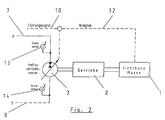
- the directional mass (1) is driven by a hydraulic adjustment motor (3) via a directional gear (2).
- the height-adjustable mass (4) is also driven by a hydraulic adjustment motor (6) via a gear (5).
- the gear (5) is, for example, a spindle drive according to FIG. 4.
- the directionally adjustable mass (1) is in this Case designed as a tower and the height-adjustable mass (4) as a weapon of an armored vehicle.
- the hydraulic adjustment motors (3, 6) are connected to a hydraulic system via a pressure line (7) and a tank line (8).
- the hydraulic adjustment motors (3,6) can be controlled in both directions of rotation and can be continuously adjusted between the respective maximum speeds.
- the adjustment signal is formed by a command signal (9, 10) in comparison to an actual signal (11, 12).
- the command signal comes from fire control electronics, not shown.
- the hydraulic adjustment motor (3) is operated so that the pressure in the tank line (8) also does not fall below a certain minimum pressure.
- the formation of cavitation must be prevented, in which gas accumulations form in the area of the hydraulic fluid.
- the pressure signal from the sensor (13) leads to a limitation of an acceleration phase
- the pressure signal from the sensor (14) leads to a limitation of a deceleration phase.
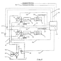
- FIG. 3 shows the entire straightening system of a device designed as an armored vehicle.
- the supply of the straightening system is shown by an engine (15) which drives a hydraulic pump (16).
- This can be a pump with a constant delivery volume or, as shown, a pump with a variable delivery volume.
- the pump sucks hydraulic fluid from a tank (17), which is preferably designed to be closed and optionally provided with a slight pre-pressure.
- a tank (17) which is preferably designed to be closed and optionally provided with a slight pre-pressure.
- This shows that the hydraulic system of the straightening system does not contain any accumulators or cylinders which absorb or release larger quantities of oil. So that the volume of the tank (17) can be kept small.
- the amount of oil in the circuit is constant at almost every moment.
- the pressure control device is also used to switch the pressure control pump (16) to unpressurized circulation when the armored vehicle is driven with the weapon system lashed.
- the lashing can cause brakes (19, 20) on the gear trains between the hydraulic adjustment motors (3,6) and the straightenable masses (1,4).
- These brakes (19, 20) are controlled by switching valves (21, 22) in such a way that they are closed in the depressurized state and are opened when the pressure in the line (7) is applied.
- the pressure sensors (23, 24) are arranged in the lines (7, 8) so that they jointly monitor the pressure level for both hydraulic adjustment motors (3, 6).
- the entire straightening system is controlled by a control device (25) which processes the height and side of the fire control signals (26) together with the system-internal signals such as the straightening signals (27,28) and the pressure sensor signals (29,30) and control signals (31,32 ) for the hydraulic adjustment motors (3,6) provides a control signal (33) for the pressure regulating hydraulic pump (16) and control signals (34,35) for the switching valves (21,22) which control the brakes.
- a height adjustment drive with a weapon (36) for an armored vehicle is shown, on the weapon lock (37) of which a threaded spindle (38) is articulated via a joint (39).
- a spindle nut (40) is mounted in a gear box (41), which in turn is mounted in the tower with a joint (42). If the spindle nut (40) is rotated, it causes a change in the distance between the joints (39, 42) and acts like a height adjustment cylinder.
- the spindle nut (40) itself is driven by a hydraulic adjustment motor (44) via gearwheels (43) in the gearbox (41).
- a brake (45) on the gearbox (41) which has the task of locking the weapon in a rest position or of supporting the braking action of the hydraulic adjustment motor in the event of deceleration from a directional movement.
Landscapes
- Engineering & Computer Science (AREA)
- General Engineering & Computer Science (AREA)
- Fluid-Pressure Circuits (AREA)
Applications Claiming Priority (2)
| Application Number | Priority Date | Filing Date | Title |
|---|---|---|---|
| DE4003256 | 1990-02-03 | ||
| DE4003256A DE4003256A1 (de) | 1990-02-03 | 1990-02-03 | Hydraulische richtanlage fuer waffen von kampffahrzeugen |
Publications (3)
| Publication Number | Publication Date |
|---|---|
| EP0440946A2 EP0440946A2 (de) | 1991-08-14 |
| EP0440946A3 EP0440946A3 (en) | 1992-07-15 |
| EP0440946B1 true EP0440946B1 (de) | 1994-08-03 |
Family
ID=6399392
Family Applications (1)
| Application Number | Title | Priority Date | Filing Date |
|---|---|---|---|
| EP90124416A Expired - Lifetime EP0440946B1 (de) | 1990-02-03 | 1990-12-17 | Hydraulische Richtanlage für Waffen von Kampffahrzeugen |
Country Status (3)
| Country | Link |
|---|---|
| US (1) | US5210371A (enExample) |
| EP (1) | EP0440946B1 (enExample) |
| DE (2) | DE4003256A1 (enExample) |
Families Citing this family (9)
| Publication number | Priority date | Publication date | Assignee | Title |
|---|---|---|---|---|
| US6269730B1 (en) * | 1999-10-22 | 2001-08-07 | Precision Remotes, Inc. | Rapid aiming telepresent system |
| RU2203470C2 (ru) * | 2001-01-30 | 2003-04-27 | Открытое акционерное общество Акционерная компания "Туламашзавод" | Способ дистанционного управления скоростями и углами наведения артустановки и установка для его осуществления |
| RU2211173C1 (ru) * | 2001-11-29 | 2003-08-27 | Государственное унитарное предприятие "Всероссийский научно-исследовательский институт "Сигнал" | Подвижная вертолетная пушечная установка |
| RU2233415C2 (ru) * | 2002-07-16 | 2004-07-27 | Государственное унитарное предприятие "Всероссийский научно-исследовательский институт "Сигнал" | Артиллерийская установка |
| RU2258886C1 (ru) * | 2004-03-30 | 2005-08-20 | Государственное унитарное предприятие "Конструкторское бюро приборостроения" | Система вертикального наведения зенитного вооружения |
| RU2340857C2 (ru) * | 2007-01-09 | 2008-12-10 | Открытое акционерное общество специального машиностроения и металлургии "Мотовилихинские заводы" | Гидравлический привод механизма горизонтального наведения артиллерийской установки |
| US7895930B2 (en) * | 2007-01-23 | 2011-03-01 | Foster-Miller, Inc. | Weapon mount |
| RU2403185C1 (ru) * | 2009-05-22 | 2010-11-10 | Открытое акционерное общество "Камов" | Система для автоматического наведения и стабилизации подвижной вертолетной пушечной установки |
| US8607686B2 (en) * | 2011-01-21 | 2013-12-17 | Control Solutions LLC | Controlled vehicle turret apparatus and method |
Citations (1)
| Publication number | Priority date | Publication date | Assignee | Title |
|---|---|---|---|---|
| CH221035A (de) * | 1941-12-01 | 1942-05-15 | W Baur Franz | Stufenlos regelbares, hydraulisches Übersetzungs- und Umkehrgetriebe, insbesondere für Flab.-Geschütz-Richtapparate. |
Family Cites Families (14)
| Publication number | Priority date | Publication date | Assignee | Title |
|---|---|---|---|---|
| GB476590A (en) * | 1935-06-15 | 1937-12-13 | Gen Hydraulic Company | Improvements in power transmission gear |
| US2304566A (en) * | 1939-12-02 | 1942-12-08 | Boeing Aircraft Co | Fire control mechanism |
| DE908823C (de) * | 1941-11-09 | 1954-04-12 | Messerschmitt Boelkow Blohm | Hydraulische Anlage zum Verstellen von Waffenstaenden fuer Flugzeuge |
| US2528645A (en) * | 1945-06-22 | 1950-11-07 | Massachusetts Inst Technology | Hydraulic power transmission apparatus |
| US2969688A (en) * | 1949-05-12 | 1961-01-31 | Hackelman Denver Eldin | Hand control for a servo system |
| FR1068005A (fr) * | 1952-09-12 | 1954-06-22 | Ct De Rech S Hydrauliques Et E | Commande hydraulique à distance, asservie à l'observation continue du mouvement d'un mobile |
| US2948193A (en) * | 1953-09-08 | 1960-08-09 | Ibm | Alternating pulse servo system |
| DE2113144A1 (de) * | 1971-03-18 | 1972-09-21 | Messerschmitt Boelkow Blohm | Hydraulisch betaetigbare Abschussanlage |
| US4020407A (en) * | 1973-03-02 | 1977-04-26 | Etat Francais | Control system for tracking a moving target |
| SE389639B (sv) * | 1974-12-18 | 1976-11-15 | Bofors Ab | Hydrostatisk drivning av artilleripjes med ytterligare funktioner |
| CH593476A5 (enExample) * | 1975-05-23 | 1977-11-30 | Oerlikon Buehrle Ag | |
| CH592862A5 (en) * | 1975-09-08 | 1977-11-15 | Oerlikon Buehrle Ag | Aiming device for firearm on turret - has hydraulic motors with short pipeline for firearm movements |
| US4573397A (en) * | 1982-10-29 | 1986-03-04 | General Motors Corporation | Turret control system |
| DE3536858C1 (de) * | 1985-10-16 | 1986-11-06 | Maschinenfabrik Glückauf Beukenberg GmbH & Co, 4650 Gelsenkirchen | Steuerung für einen Waffenrichtantrieb |
-
1990
- 1990-02-03 DE DE4003256A patent/DE4003256A1/de active Granted
- 1990-12-17 DE DE59006699T patent/DE59006699D1/de not_active Expired - Fee Related
- 1990-12-17 EP EP90124416A patent/EP0440946B1/de not_active Expired - Lifetime
-
1991
- 1991-02-04 US US07/650,297 patent/US5210371A/en not_active Expired - Fee Related
Patent Citations (1)
| Publication number | Priority date | Publication date | Assignee | Title |
|---|---|---|---|---|
| CH221035A (de) * | 1941-12-01 | 1942-05-15 | W Baur Franz | Stufenlos regelbares, hydraulisches Übersetzungs- und Umkehrgetriebe, insbesondere für Flab.-Geschütz-Richtapparate. |
Also Published As
| Publication number | Publication date |
|---|---|
| DE4003256C2 (enExample) | 1992-05-21 |
| US5210371A (en) | 1993-05-11 |
| EP0440946A3 (en) | 1992-07-15 |
| EP0440946A2 (de) | 1991-08-14 |
| DE4003256A1 (de) | 1991-08-08 |
| DE59006699D1 (de) | 1994-09-08 |
Similar Documents
| Publication | Publication Date | Title |
|---|---|---|
| EP2039582B1 (de) | Aktiver hydraulischer Dämpfer und hydraulischer Stellantrieb | |
| DE19934782C2 (de) | Verfahren und Anordnung zum Steuern eines hydraulischen Fahrzeugantriebs | |
| EP1251059B1 (de) | Verfahren zum Steuern eines Servolenksystems | |
| EP0248178A1 (de) | Kraftfahrzeug mit einer Antriebseinrichtung für eine Hinterachse | |
| EP2181221A1 (de) | Hydraulikantrieb insbesondere eines baggers insbesondere für ein drehwerk | |
| DE2450874B2 (de) | Blockiergeschützte hydraulische Fahrzeugbremsanlage | |
| DE102013210563A1 (de) | Verfahren zur Steuerung und Regelung eines elektrohydraulischen Bremssystems und Bremssystem | |
| EP0440946B1 (de) | Hydraulische Richtanlage für Waffen von Kampffahrzeugen | |
| DE3640082A1 (de) | Elektrohydrostatischer aktuator | |
| DE10056388A1 (de) | Elektro-hydraulisches Lenksystem | |
| EP1065379A2 (de) | Elektrohydraulische Druckversorgung mit verstellbarer Pumpe und regelbarem elektrischem Antrieb | |
| EP1656224B1 (de) | Einrichtung zur steuerung des ziehvorgangs bei einer transferpresse | |
| DE4129610A1 (de) | Niveauregelsystem fuer kraftfahrzeuge | |
| DE102017202273A1 (de) | Hydrostatisches Getriebe und Verfahren zur Bremsung damit | |
| DE102017207570A1 (de) | Hydrostatisches Getriebe und Verfahren zur Bremsung damit | |
| EP1561054B1 (de) | Steuerung für einen hydrostatischen fahrantrieb | |
| DE2557149A1 (de) | Vorrichtung zum erzeugen eines oeldrucks fuer ein artilleriegeschuetz o.dgl. | |
| EP1828643B1 (de) | Verfahren zum abbremsen eines mittels eines hydrostatischen getriebes angetriebenen fahrzeugs sowie ein hydrostatischer antrieb | |
| DE102018208211A1 (de) | Verfahren zur Steuerung einer elektronisch schlupfregelbaren Fremdkraftbremsanlage | |
| DE19654781A1 (de) | Hilfseinrichtung zur Realisierung einer Redundanz für die Energieversorgung von Flugsteuerungsantrieben | |
| EP2499401B1 (de) | Kalibrierverfahren und hydraulischer fahrantrieb | |
| EP0470950B1 (de) | Vorrichtung zur elektro-hydraulischen betätigung einer ein verteilerdifferentialgetriebe eines kraftfahrzeugs sperrenden kupplung | |
| DE8615387U1 (de) | Kraftfahrzeug, insbesondere im Stop-and-Go-Verkehr betriebenes Nutzfahrzeug | |
| DE10065367C2 (de) | Regelung der Drehzahl eines hydrostatischen Motors | |
| DE4013651A1 (de) | Lenkungssteuersystem fuer fahrzeuge |
Legal Events
| Date | Code | Title | Description |
|---|---|---|---|
| PUAI | Public reference made under article 153(3) epc to a published international application that has entered the european phase |
Free format text: ORIGINAL CODE: 0009012 |
|
| AK | Designated contracting states |
Kind code of ref document: A2 Designated state(s): CH DE FR GB IT LI |
|
| PUAL | Search report despatched |
Free format text: ORIGINAL CODE: 0009013 |
|
| AK | Designated contracting states |
Kind code of ref document: A3 Designated state(s): CH DE FR GB IT LI |
|
| 17P | Request for examination filed |
Effective date: 19920907 |
|
| 17Q | First examination report despatched |
Effective date: 19940126 |
|
| GRAA | (expected) grant |
Free format text: ORIGINAL CODE: 0009210 |
|
| AK | Designated contracting states |
Kind code of ref document: B1 Designated state(s): CH DE FR GB IT LI |
|
| PG25 | Lapsed in a contracting state [announced via postgrant information from national office to epo] |
Ref country code: IT Free format text: LAPSE BECAUSE OF FAILURE TO SUBMIT A TRANSLATION OF THE DESCRIPTION OR TO PAY THE FEE WITHIN THE PRE;WARNING: LAPSES OF ITALIAN PATENTS WITH EFFECTIVE DATE BEFORE 2007 MAY HAVE OCCURRED AT ANY TIME BEFORE 2007. THE CORRECT EFFECTIVE DATE MAY BE DIFFERENT FROM THE ONE RECORDED.SCRIBED TIME-LIMIT Effective date: 19940803 Ref country code: GB Effective date: 19940803 Ref country code: FR Effective date: 19940803 |
|
| REF | Corresponds to: |
Ref document number: 59006699 Country of ref document: DE Date of ref document: 19940908 |
|
| EN | Fr: translation not filed | ||
| GBV | Gb: ep patent (uk) treated as always having been void in accordance with gb section 77(7)/1977 [no translation filed] |
Effective date: 19940803 |
|
| PLBE | No opposition filed within time limit |
Free format text: ORIGINAL CODE: 0009261 |
|
| STAA | Information on the status of an ep patent application or granted ep patent |
Free format text: STATUS: NO OPPOSITION FILED WITHIN TIME LIMIT |
|
| 26N | No opposition filed | ||
| PGFP | Annual fee paid to national office [announced via postgrant information from national office to epo] |
Ref country code: DE Payment date: 19991102 Year of fee payment: 11 |
|
| PGFP | Annual fee paid to national office [announced via postgrant information from national office to epo] |
Ref country code: CH Payment date: 20000327 Year of fee payment: 10 |
|
| PG25 | Lapsed in a contracting state [announced via postgrant information from national office to epo] |
Ref country code: LI Free format text: LAPSE BECAUSE OF NON-PAYMENT OF DUE FEES Effective date: 20001231 Ref country code: CH Free format text: LAPSE BECAUSE OF NON-PAYMENT OF DUE FEES Effective date: 20001231 |
|
| REG | Reference to a national code |
Ref country code: CH Ref legal event code: PL |
|
| PG25 | Lapsed in a contracting state [announced via postgrant information from national office to epo] |
Ref country code: DE Free format text: LAPSE BECAUSE OF NON-PAYMENT OF DUE FEES Effective date: 20020702 |