EP0440418B1 - Verfahren zur Bestimmung des Profils von Reifen - Google Patents
Verfahren zur Bestimmung des Profils von Reifen Download PDFInfo
- Publication number
- EP0440418B1 EP0440418B1 EP91300659A EP91300659A EP0440418B1 EP 0440418 B1 EP0440418 B1 EP 0440418B1 EP 91300659 A EP91300659 A EP 91300659A EP 91300659 A EP91300659 A EP 91300659A EP 0440418 B1 EP0440418 B1 EP 0440418B1
- Authority
- EP
- European Patent Office
- Prior art keywords
- data
- tyre
- axis
- determining
- profile
- Prior art date
- Legal status (The legal status is an assumption and is not a legal conclusion. Google has not performed a legal analysis and makes no representation as to the accuracy of the status listed.)
- Expired - Lifetime
Links
- 238000000034 method Methods 0.000 title claims description 13
- 238000005259 measurement Methods 0.000 claims description 13
- 238000000926 separation method Methods 0.000 claims 1
- 238000001514 detection method Methods 0.000 description 14
- 238000010586 diagram Methods 0.000 description 4
- 230000002093 peripheral effect Effects 0.000 description 4
- 230000003287 optical effect Effects 0.000 description 2
- 238000012217 deletion Methods 0.000 description 1
- 230000037430 deletion Effects 0.000 description 1
- 238000013208 measuring procedure Methods 0.000 description 1
Images


Classifications
-
- G—PHYSICS
- G01—MEASURING; TESTING
- G01M—TESTING STATIC OR DYNAMIC BALANCE OF MACHINES OR STRUCTURES; TESTING OF STRUCTURES OR APPARATUS, NOT OTHERWISE PROVIDED FOR
- G01M17/00—Testing of vehicles
- G01M17/007—Wheeled or endless-tracked vehicles
- G01M17/02—Tyres
- G01M17/027—Tyres using light, e.g. infrared, ultraviolet or holographic techniques
-
- G—PHYSICS
- G01—MEASURING; TESTING
- G01B—MEASURING LENGTH, THICKNESS OR SIMILAR LINEAR DIMENSIONS; MEASURING ANGLES; MEASURING AREAS; MEASURING IRREGULARITIES OF SURFACES OR CONTOURS
- G01B11/00—Measuring arrangements characterised by the use of optical techniques
- G01B11/22—Measuring arrangements characterised by the use of optical techniques for measuring depth
-
- G—PHYSICS
- G01—MEASURING; TESTING
- G01B—MEASURING LENGTH, THICKNESS OR SIMILAR LINEAR DIMENSIONS; MEASURING ANGLES; MEASURING AREAS; MEASURING IRREGULARITIES OF SURFACES OR CONTOURS
- G01B11/00—Measuring arrangements characterised by the use of optical techniques
- G01B11/24—Measuring arrangements characterised by the use of optical techniques for measuring contours or curvatures
-
- G—PHYSICS
- G01—MEASURING; TESTING
- G01B—MEASURING LENGTH, THICKNESS OR SIMILAR LINEAR DIMENSIONS; MEASURING ANGLES; MEASURING AREAS; MEASURING IRREGULARITIES OF SURFACES OR CONTOURS
- G01B11/00—Measuring arrangements characterised by the use of optical techniques
- G01B11/24—Measuring arrangements characterised by the use of optical techniques for measuring contours or curvatures
- G01B11/255—Measuring arrangements characterised by the use of optical techniques for measuring contours or curvatures for measuring radius of curvature
Definitions
- the present invention relates to a method for determining the profile of tyres.
- Japanese Utility Model Publication SHO 62-102110 discloses an apparatus for measuring the radius of a tyre tread.
- This comprises a means for measuring the crown radius of a tyre which is an optical sensor for measuring the distance to the crown portion of the tyre from the sensor without contact to the tyre.
- the sensor is mounted so that it can be moved in the direction of the axis of the tyre and thus scan across the tread region.
- the output signals in relation to the distance from the sensor to the surface of the tyre and the position of the optical sensor in relation to the axial direction of the tyre are both used to calculate the profile of the tyre crown portion by means of measuring three points on the tread profile and calculating from the said three points.
- the conventional apparatus for measuring the radius of the crown of a tyre is adapted to determine the said crown radius from three points on the tread profile and is therefore unable to accurately and rapidly measure the profile of the tread shoulder portions. Furthermore the apparatus fails to give measurements of sufficiently high accuracy since it does not measure variations in crown shape and simply averages over three points.
- An object of the present invention is to provide a method to determine the profile of tyres which is adapted to determine the radius of curvature in short section of the tyre with higher accuracy.
- the present invention comprises mounting the tyre on a measuring apparatus with the tyre rotation axis being in parallel to an X axis, measuring perpendicularly to the X axis a Y axis distance (Yi) from a Y axis distance measuring means of the measuring apparatus to the tyre tread and storing such measurement as Y data, measuring an X axis position of the Y axis distance measuring means corresponding to the Y data measurement and storing such a measurement as X data; repeating the measurement and storing of Y axis distances and X axis positions while moving the Y axis distance measuring means along the X axis; characterised by inputting reference data (-q,-p,+p,+q) on the tyre to be measured into a data memory means, said reference data, based on a tyre equator line set at a zero X axis point, including standard X axis lengths (-p to +p
- the Y measuring means is preferably a laser sensor movable in the direction of the X axis.
- the movement in the direction of the X axis may be provided by a feed screw engaging the Y measuring means and disposed parallel to the X axis.
- a rotary encoder for the feed screw may be used to detect rotation of the feed screw to give the X data.
- the data memory means and the radius calculating means are preferably a computer.
- the apparatus for carrying out the invention may also include rotation means for the tyre so that it can be rotated about its X axis and angular position R detection means are provided to detect the angle of rotation of the tyre and provide an R data output. Data memory means are then provide to store said R angle data and the apparatus further comprises radial runout (RRO) calculation means to determine the radial runout of the tyre from the Y and R data in the memory means.
- RRO radial runout
- the method may also include computation of radial runout of the tyre using R angle data corresponding to particular X and Y values for rotation of the tyre.
- a tyre mount 2 is fixedly provided on a base 1.
- the tyre 4 is mounted on a rotatable shaft 3 which extends in a vertical direction.
- the axis of the shaft 3 will hereinafter be referred to as the "X-axis”.
- a handle 5 is fixed to the upper end of the shaft 3 for rotating the shaft 3 and thus the tyre 4.
- the shaft 3 is provided at its lower end with a R detection means 6 for sensing the angle of rotation R of the shaft 3.
- the R detection means 6 comprises a rotary encoder.
- the base 1 is provided with rails (not shown) on which a movable table 7a is slidably mounted for movement in a horizontal direction (hereinafter referred to as the "direction of the Y-axis") intersecting the X-axis at right angles.
- the table 7a is movable by rotating a threaded rod (not shown) by a handle 7b.
- the movable table 7a carries a measuring unit 7 thereon.
- the measuring unit 7 has a rotatable feed screw 8 extending vertically parallel to the X-axis.
- a motor 9 for rotating the feed screw 8 is provided in the lower portion of the measuring unit 7.
- a Y distance measuring means 10 is mounted in the measuring unit 7 in a screw-thread engagement with the feed screw 8 and movable upwardly and downwardly by rotation of the feed screw 8.
- the Y measuring means 10 comprises a laser sensor and is able to measure the distance Yi from the peripheral surface of the tyre 4 in the direction of the Y-axis without contacting the tyre.
- Coupled to the feed screw 8 is an X detection means 11 for measuring the position Xi of the Y detection means 10 with respect to the X-direction.
- the X detection means 11 comprises a rotary encoder for counting the number of revolutions of the feed screw 8. The position of the Y detection means 10 in the X-direction is found by multiplying the thread pitch of the feed screw 8 by the number of revolutions.
- the range of movement in X-direction is such that measurements can be obtained for tyres of every category.
- a personal computer 12 provides a data memory means 13 for storing the data from the X, Y and R detection means 11, 10 and 6, and radius calculating means 14 for calculating the radius of the tyre tread from the stored data.
- the calculating means 14 comprises division means 16 for dividing the Xi and Yi data into groups for a plurality of portions of the width of the tyre such for example as the crown portion and shoulder portions, and arithmetic means 16 for calculating the radii of the respective crown and shoulder portions from the corresponding data group from the division means 15.
- the computer 12 is connected to a display 17 and an X-Y plotter 18 to show the profile and radii of the section of the tyre tested. Also connected to the computer is RRO display means 19 for displaying the RRO (radial runout) of the tyre determined from the X and R data in the data memory means 13.
- the RRO display means 19 comprises an X-Y recorder.
- Indicated at 20 is an input unit for the personal computer 12.
- the radius of the tyre is measured in the following manner.
- the tyre 4 is mounted and inflated on a rim and the assembly is mounted on the shaft 3.
- the shaft 3 is locked against rotation.
- the movable table 7a is moved in the Y-direction to set the distance Yi between the peripheral surface of the tyre 4 and the Y measuring means 10 to a predetermined value.
- the motor 9 is then continuously driven to continuously rotate the feed screw 8 and continuously move the Y measuring means 10. During this movement, measurements are taken for Yi at predetermined intervals. In this case, the distance Yi between the Y measuring means 10 and the peripheral surface of the tyre 4 is measured by the Y measuring means 10, and the position Xi of the Y detection means 10 in the X-direction is measured by the X detection means 11.
- Each pair of Xi and Yi data items is stored in the data memory means 13 of the computer 12 as the coordinates of a point.
- the profile of the tyre 4 is calculated by the computer 12.
- the profile can be monitored as displayed on the display 17 as seen in Figure 2 (I).
- the profile can also be displayed on the X-Y plotter 18.
- At least five sets of data per centimetre of tyre width are collected for the profile data.
- the data in the memory means 13 is first subdivided into groups by the division means 15. This can be into data for the tyre crown portion and data for the shoulder portions.
- the data is divided in the following manner.
- the value X representing each end is determined by detecting the value Y equal to or exceeding a certain reference value. More specifically, the value Y is compared with the predetermined reference value, and upon the value Y equal to or exceeding the reference value, the corresponding X value is taken as the end value of the X data.
- the value X at the mid-point between the opposite ends is calculated.
- the calculated mid-point of the X data corresponds to or represents the equator of the tyre and is used to divided the tread of the tyre 4 into the crown portion and the shoulder portions.
- a region is specified to either side of the centre which is the portion of the tyre equator to define the crown portion as shown in Figure 3. The regions from these limits to the sides of the tyre thus define the shoulder portions.
- the mid-point value of the data must be detected.
- the X data coordinate system is then so transformed that the mid-point value of X data serves as the origin of the X-axis.
- reference values are entered by the input unit 20 to specify the region for which calculation is to be performed.
- the reference values define the width of the crown portion or shoulder portion. These values to be entered represent the distance as measured from the equator.
- the data between the opposite ends can be divided into the data as to the crown portion and the data as to the shoulder portions.
- the region of the crown portion is specified as the range of from -p to +p.
- the X data from -p to +p is taken as the data as to the crown portion.
- the range of -q to -p and the range of +p to +q are entered as the regions of the shoulder portions, the X data from -q to -p and from +p to +q among other items of data between opposite ends is taken as the data for the shoulder portions.
- the stored data is divided by the division means 15 into groups for the crown portion and shoulder portions.
- the bottom data represents the grooves formed in the tyre tread and if not detected and removed is an impediment to the calculation of an accurate radius of the tyre crown portion or shoulder portions and must therefore be deleted.
- the groove bottom data is identified by reference to Y values.
- the data for the top point of the tyre is detected first (subsequent to the detection of the opposite end values and mid-point value of the data).
- the Y measurements which are above a certain reference value beyond the Y measurement of the top point are interpreted as being groove data. Different reference values are used for the crown portion and the shoulder portions. The groove bottom data identified as such is deleted so as not to be used in the subsequent calculation.
- the data to be deleted is identified according to whether four consecutive Y values are smooth values.
- the value Yi is the data to be used when the four consecutive values of Yi, Yi+1, Yi + 2 and Yi+3 fulfil the requirements of: (Yi - Yi+1)2 ⁇ d (Yi - Yi+2)2 ⁇ e (Yi - Y1+3)2 ⁇ f wherein d, e and f are predetermined reference values.
- this section is interpolated with data to make the data items sufficiently complete.
- the data is divided for the crown portion and the shoulder portions by the division means 15, and the data to be used is determined.
- the radii of the crown portion and the shoulder portions are then calculated by the arithmetic means 16.
- the coefficients a, b and c are determined by least square approximation.
- the crown portion tread radius thus obtained is indicated at (III) in Figure 2, and the shoulder portion tread radius obtained at (II) in Figure 2.
- the display 17 shows these radii.
- the radius of the desired region can be determined by the method described above. At least the tread crown radius and the tread shoulder radius can be determined at the same time.
- the shaft 3 is unlocked, and the tyre 4 is rotated with the handle 5.
- the angle of rotation R is detected by the R detection means 6, and at the same time, the distance Y from the tyre peripheral surface is measured by the Y detection means 10.
- the point (R, Y) is stored in the data memory means 13. Such points over the entire periphery of the tyre are measured and stored.
- the R and Y data is fed to the RRO display means 19 to present a graph as shown in Figure 5.
- the measuring unit 7 is provided with positioning jigs (stoppers) 21 for positioning the tyre surface within the range of m ⁇ 15mm wherein m is the fixed focal length of the Y detection means 10 to thereby regulate the measuring range.
- stoppers 21 When the measuring unit 7 is moved towards the tyre, the forward ends of the stoppers 21 come into contact with the tyre surface, whereupon the measuring unit 7 is halted.
Landscapes
- Physics & Mathematics (AREA)
- General Physics & Mathematics (AREA)
- Length Measuring Devices With Unspecified Measuring Means (AREA)
- Length Measuring Devices By Optical Means (AREA)
- Tires In General (AREA)
Claims (4)
- Ein Verfahren zum Bestimmen des Profils einer Reifenlauffläche, welches die Schritte umfaßt, daß der Reifen (4) an einer Meßvorrichtung angebracht wird, wobei die Reifendrehachse parallel zu einer X-Achse ist, daß senkrecht zur X-Achse ein Y-Achse-Abstand (Yi) von einem Y-Achse-Abstandmeßmittel (10) der Meßvorrichtung zur Reifenlauffläche gemessen und eine derartige Messung als Y-Daten gespeichert wird, daß eine X-Achse-Position (Xi) des Y-Achse-Abstandmeßmittels (10) entsprechend der Y-Daten-Messung gemessen und eine derartige Messung als X-Daten gespeichert wird, daß die Messung und das Speichern der Y-Achse-Abstände (Yi) und X-Achse-Positionen (Xi) wiederholt und dabei das Y-Achse-Abstandmeßmittel (10) entlang der X-Achse bewegt wird,
gekennzeichnet durch die Schritte,
daß Referenzdaten (-q, -p, +p, +q) des zu vermessenden Reifens in ein Datenspeichermittel (13) eingegeben werden, wobei die Referenzdaten gestützt auf eine Reifenäquatorlinie, die auf einen X-Achse-Nullpunkt gesetzt ist, Standard-X-Achse-Längen (-p bis +p, -q bis -p und +p bis +q) jeweils des Kronenabschnitts und der Schulterabschnitte des Profils für den zu vermessenden Reifen umfassen, daß die Serie von X- und Y-Daten in zwei Datensätze mit Bezug auf die Referenzdaten (-q, -p, +p, +q) getrennt werden, wobei der eine Satz Punkten auf dem Kronenabschnitt der Reifenlauffläche entspricht und der andere Satz Punkten auf den Schulterabschnitten der Reifenlauffläche entspricht, und daß die Radien des Kronenabschnitts und der Schulterabschnitte der Reifenlauffläche jeweils unter Verwendung der getrennten Datensätze berechnet werden. - Ein Verfahren zum Bestimmen des Profils eines Reifens nach Anspruch 1,
dadurch gekennzeichnet,
daß die Radien der Kronen- und Schulterabschnitte berechnet werden, indem für jeden getrennten Datensatz von X und Y die Kreisgleichung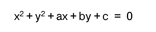

- Ein Verfahren zum Bestimmen eines Reifenlaufflächenprofils nach Anspruch 1 oder 2,
dadurch gekennzeichnet,
daß die Trennung der Serie von X- und Y-Daten in zwei Datensätze ausgeführt wird, indem die gegenüberliegenden Endwerte der gespeicherten X-Daten, für welche gespeicherte Y-Daten existieren, bestimmt werden, der Mittelpunkt zwischen diesen gegenüberliegenden End-X-Datenwerten bestimmt wird, und die X-Daten gestützt auf den Mittelpunkt mit den eingegebenen Referenzdaten (-q, -p, +p, +q) des Kronenabschnitts (-p bis +p) und der Schulterabschnitte (-q bis -p und +p bis +q) verglichen werden. - Ein Verfahren zum Bestimmen des Profils einer Reifenlauffläche nach Anspruch 1, 2 oder 3,
dadurch gekennzeichnet,
daß der Reifen um seine X-Achse gedreht wird und die R-Winkel-Daten entsprechend besonderen X- und Y-Werten berechnet werden, um die radiale Unrundheit (RRO) des Reifens bezüglich der X-Achse zu bestimmen.
Applications Claiming Priority (2)
| Application Number | Priority Date | Filing Date | Title |
|---|---|---|---|
| JP2022553A JPH0820228B2 (ja) | 1990-01-31 | 1990-01-31 | タイヤ外周面のプロファイル測定方法及びその装置 |
| JP22553/90 | 1990-01-31 |
Publications (3)
| Publication Number | Publication Date |
|---|---|
| EP0440418A2 EP0440418A2 (de) | 1991-08-07 |
| EP0440418A3 EP0440418A3 (en) | 1993-06-09 |
| EP0440418B1 true EP0440418B1 (de) | 1995-11-29 |
Family
ID=12086039
Family Applications (1)
| Application Number | Title | Priority Date | Filing Date |
|---|---|---|---|
| EP91300659A Expired - Lifetime EP0440418B1 (de) | 1990-01-31 | 1991-01-29 | Verfahren zur Bestimmung des Profils von Reifen |
Country Status (4)
| Country | Link |
|---|---|
| US (1) | US5485406A (de) |
| EP (1) | EP0440418B1 (de) |
| JP (1) | JPH0820228B2 (de) |
| DE (1) | DE69114869T2 (de) |
Cited By (2)
| Publication number | Priority date | Publication date | Assignee | Title |
|---|---|---|---|---|
| DE102006014058A1 (de) * | 2006-03-27 | 2007-10-31 | Mähner, Bernward | Vorrichtung und Verfahren zum Prüfen eines Reifens |
| CN106062508A (zh) * | 2014-03-07 | 2016-10-26 | 住友橡胶工业株式会社 | 轮胎的胎面半径测定方法及其所使用的胎面半径测定装置 |
Families Citing this family (38)
| Publication number | Priority date | Publication date | Assignee | Title |
|---|---|---|---|---|
| US5245867A (en) * | 1991-12-16 | 1993-09-21 | Bridgestone Corporation | Method and apparatus for measuring tire parameters |
| US5249460A (en) * | 1991-12-16 | 1993-10-05 | Bridgestone Corporation | Method and apparatus for measuring irregular tread wear |
| US5710718A (en) * | 1993-01-27 | 1998-01-20 | Bridgestone Corporation | Method of designing a pneumatic tire to achieve a best mode under given conditions |
| GB2294327A (en) * | 1994-10-18 | 1996-04-24 | Rank Taylor Hobson Ltd | Roundness measuring |
| US5789668A (en) * | 1996-08-15 | 1998-08-04 | Bridgestone/Firestone, Inc. | Apparatus and related methods for obtaining tire profiles including the tread and both sidewalls |
| DE19649391A1 (de) * | 1996-11-29 | 1998-06-04 | Voith Sulzer Papiermasch Gmbh | Vorrichtung und Verfahren zur Ermittlung des Durchmessers einer Rolle |
| US5987978A (en) * | 1997-04-02 | 1999-11-23 | Assembly Technology & Test Ltd. | Apparatus for testing tire tread depth |
| JP3048985B2 (ja) * | 1997-11-12 | 2000-06-05 | 新潟日本電気株式会社 | 液体濃度センサー |
| US6085429A (en) * | 1998-10-20 | 2000-07-11 | Sony Corporation | Optical disc spindle straightness testing apparatus and method |
| DE19849793C1 (de) * | 1998-10-28 | 2000-03-16 | Fraunhofer Ges Forschung | Vorrichtung und Verfahren zur berührungslosen Erfassung von Unebenheiten in einer gewölbten Oberfläche |
| US6789416B1 (en) * | 1999-01-14 | 2004-09-14 | Roger H. Tracy | Hand held probe for measuring tire tread wear |
| US6417918B1 (en) * | 1999-09-22 | 2002-07-09 | Bridgestone Corporation | Tire Inspecting method and apparatus |
| DE19959623C2 (de) * | 1999-12-10 | 2001-10-11 | Fraunhofer Ges Forschung | Verfahren und Anordnung zum Lokalisieren von zylinderförmigen Objekten |
| AU2001268451A1 (en) * | 2000-06-13 | 2001-12-24 | Fd Management, Inc. | Cosmetic composition for stressed skin under extreme conditions |
| US6741957B1 (en) | 2000-07-21 | 2004-05-25 | Daimlerchrysler Corporation | Analytical tire model for vehicle durability and ride comfort analysis |
| IT1319446B1 (it) * | 2000-11-16 | 2003-10-10 | Corghi Spa | Dispositivo per il rilevamento dei difetti geometrici della ruota diun veicolo |
| CH696448A5 (de) * | 2001-11-16 | 2007-06-15 | Martin Bodenmann | Verfahren zur Untersuchung digital erfasster Oberflächen auf ihre Welligkeit. |
| US7096150B2 (en) * | 2002-10-03 | 2006-08-22 | The Goodyear Tire & Rubber Company | Method and apparatus for correcting tire nonuniformity |
| US20040074292A1 (en) * | 2002-10-03 | 2004-04-22 | Irwin Robert Dean | Cutter assembly for correcting tire nonuniformity |
| US20050031235A1 (en) * | 2003-08-04 | 2005-02-10 | Minebea Co., Ltd. | One piece thrust-plate/shaft assembly for hydrodynamic bearing |
| EP1512953B1 (de) * | 2003-09-04 | 2008-12-10 | Snap-on Equipment Srl a unico socio. | Verfahren und Vorrichtung zum optischen Abtasten eines Fahrzeugrades |
| DE50300973D1 (de) * | 2003-09-04 | 2005-09-15 | Snap On Equip Srl Unico Socio | Punktweises optisches Abtasten der Beschaffenheit eines Luftreifens eines Fahrzeugrades (an Radauswuchtmaschine) |
| JP4668629B2 (ja) * | 2005-01-17 | 2011-04-13 | アスモ株式会社 | 電機子コアの検査方法及び検査装置 |
| DE102006014070B4 (de) * | 2006-03-27 | 2008-02-07 | Mähner, Bernward | Vorrichtung und Verfahren zum Prüfen eines Reifens, insbesondere mittels eines interferometrischen Messverfahrens |
| JP2008076312A (ja) * | 2006-09-22 | 2008-04-03 | Fine Tech Corp | 測長装置 |
| JP5046688B2 (ja) * | 2007-03-08 | 2012-10-10 | 株式会社神戸製鋼所 | タイヤ形状検出装置,タイヤ形状検出方法 |
| WO2009070146A1 (en) * | 2007-11-30 | 2009-06-04 | Societe De Technologie Michelin | Automated surface preparations for the inner surface of a tire |
| US7805987B1 (en) * | 2008-08-19 | 2010-10-05 | Smith Bradley R | System and method for pneumatic tire defect detection |
| JP5553712B2 (ja) * | 2010-09-01 | 2014-07-16 | 横浜ゴム株式会社 | タイヤ性能測定方法及びタイヤ性能測定装置 |
| DE102012224260A1 (de) * | 2012-12-21 | 2014-06-26 | Robert Bosch Gmbh | Vorrichtung und Verfahren zur Messung der Profiltiefe eines Reifens |
| KR20160064161A (ko) * | 2013-09-26 | 2016-06-07 | 꽁빠니 제네날 드 에따블리세망 미쉘린 | 국부적인 타이어 표면 변형의 보정 |
| EP3059546B1 (de) * | 2015-02-20 | 2017-08-09 | Snap-on Equipment S.r.l. | Verfahren zur erkennung der exzentrizität eines reifens für fahrzeugräder in verfahren zur wartung dieser räder und vorrichtung zur wartung von fahrzeugrädern |
| US10789773B2 (en) * | 2016-03-04 | 2020-09-29 | TIREAUDIT.COM, Inc. | Mesh registration system and method for diagnosing tread wear |
| US11472234B2 (en) * | 2016-03-04 | 2022-10-18 | TIREAUDIT.COM, Inc. | Mesh registration system and method for diagnosing tread wear |
| US10247641B2 (en) * | 2016-03-04 | 2019-04-02 | TIREAUDIT.COM, Inc. | Mesh registration system and method for diagnosing tread wear |
| WO2018068143A1 (en) * | 2016-10-13 | 2018-04-19 | Mccain Foods Limited | Method, medium, and system for detecting potato virus in a crop image |
| EP3495767B1 (de) * | 2017-12-11 | 2022-01-05 | Butler Engineering & Marketing S.p.A. | Einheit zur erfassung geometrischer merkmale einer komponente eines bereiften rades eines fahrzeugs |
| CN118310463B (zh) * | 2024-04-17 | 2024-11-05 | 哈工科讯(沈阳)工业技术研究院有限公司 | 基于旋转变压器的转动跳动监测系统及方法 |
Family Cites Families (15)
| Publication number | Priority date | Publication date | Assignee | Title |
|---|---|---|---|---|
| US3918816A (en) * | 1974-04-22 | 1975-11-11 | Autech Corp | Tire inspection apparatus |
| DE2834660A1 (de) * | 1978-08-08 | 1980-02-21 | Honeywell Gmbh | Laser-entfernungsmesser |
| US4275589A (en) * | 1979-04-19 | 1981-06-30 | Bandag Incorporated | Method and apparatus for non-destructive inspection of tires |
| US4457625A (en) * | 1981-07-13 | 1984-07-03 | Itek Corporation | Self calibrating contour measuring system using fringe counting interferometers |
| JPS6080704A (ja) * | 1983-10-11 | 1985-05-08 | Mitsutoyo Mfg Co Ltd | 立体物測定機 |
| JPS6186606A (ja) * | 1984-10-05 | 1986-05-02 | Hitachi Ltd | 非接触形状測定方法 |
| US4670289A (en) * | 1985-02-28 | 1987-06-02 | The Firestone Tire & Rubber Company | Tire marker |
| JPS62102110A (ja) * | 1985-10-30 | 1987-05-12 | Nissan Motor Co Ltd | 経路誘導装置における計測位置の表示方法 |
| DE3625564A1 (de) * | 1986-07-29 | 1988-02-04 | Hegenscheidt Gmbh Wilhelm | Verfahren zur ermittlung des durchmessers der raeder von schienenfahrzeugen und einrichtung hierzu |
| US4783992A (en) * | 1987-06-26 | 1988-11-15 | Bridgestone Corporation | Method of detecting configuration of tire |
| US4910411A (en) * | 1988-02-12 | 1990-03-20 | Sumitumo Rubber Industries | Apparatus for inspecting a side wall of a tire |
| US4936138A (en) * | 1988-09-14 | 1990-06-26 | Oliver Rubber Company | Method and apparatus for tire inspection |
| JPH02296127A (ja) * | 1989-05-10 | 1990-12-06 | Bridgestone Corp | 空気入りタイヤの欠陥検査方法 |
| US5249460A (en) * | 1991-12-16 | 1993-10-05 | Bridgestone Corporation | Method and apparatus for measuring irregular tread wear |
| US5245867A (en) * | 1991-12-16 | 1993-09-21 | Bridgestone Corporation | Method and apparatus for measuring tire parameters |
-
1990
- 1990-01-31 JP JP2022553A patent/JPH0820228B2/ja not_active Expired - Fee Related
-
1991
- 1991-01-29 EP EP91300659A patent/EP0440418B1/de not_active Expired - Lifetime
- 1991-01-29 DE DE69114869T patent/DE69114869T2/de not_active Expired - Fee Related
-
1993
- 1993-07-26 US US08/096,837 patent/US5485406A/en not_active Expired - Lifetime
Cited By (4)
| Publication number | Priority date | Publication date | Assignee | Title |
|---|---|---|---|---|
| DE102006014058A1 (de) * | 2006-03-27 | 2007-10-31 | Mähner, Bernward | Vorrichtung und Verfahren zum Prüfen eines Reifens |
| DE102006014058B4 (de) * | 2006-03-27 | 2008-04-17 | Mähner, Bernward | Vorrichtung und Verfahren zum optischen Prüfen eines Reifens |
| CN106062508A (zh) * | 2014-03-07 | 2016-10-26 | 住友橡胶工业株式会社 | 轮胎的胎面半径测定方法及其所使用的胎面半径测定装置 |
| CN106062508B (zh) * | 2014-03-07 | 2019-05-28 | 住友橡胶工业株式会社 | 轮胎的胎面半径测定方法及其所使用的胎面半径测定装置 |
Also Published As
| Publication number | Publication date |
|---|---|
| DE69114869T2 (de) | 1996-04-18 |
| US5485406A (en) | 1996-01-16 |
| JPH0820228B2 (ja) | 1996-03-04 |
| JPH03226615A (ja) | 1991-10-07 |
| EP0440418A2 (de) | 1991-08-07 |
| EP0440418A3 (en) | 1993-06-09 |
| DE69114869D1 (de) | 1996-01-11 |
Similar Documents
| Publication | Publication Date | Title |
|---|---|---|
| EP0440418A2 (de) | Verfahren zur Bestimmung des Profils von Reifen | |
| US5243665A (en) | Component surface distortion evaluation apparatus and method | |
| US4158507A (en) | Laser measuring system for inspection | |
| JP2809295B2 (ja) | 座標測定機及びその測定方法 | |
| US7376261B2 (en) | Surface scan measuring device and method of forming compensation table for scanning probe | |
| US4084324A (en) | Measuring instrument | |
| US5249460A (en) | Method and apparatus for measuring irregular tread wear | |
| CN108007353B (zh) | 一种旋转式激光轮廓测量方法、存储装置及其测量装置 | |
| EP1783454B1 (de) | Formmessgerät | |
| CA2746712A1 (en) | Measurement method and device for thread parameters | |
| CN104897105B (zh) | 直线形状测定方法及直线形状测定装置 | |
| WO2001018734A8 (en) | Calibration process for shape measurement | |
| US6212481B1 (en) | Method and apparatus for automatic shape computing for contour shape determining machine | |
| KR100292610B1 (ko) | 카메라와레이저변위센서를혼합한비접촉식선박용곡판부재계측장치 | |
| US4756621A (en) | Apparatus for measuring a length of displacement | |
| JP2935603B2 (ja) | 真直度測定機能付真円度測定装置 | |
| JP2996165B2 (ja) | 形状測定方法及びそれを用いた形状測定装置 | |
| CN85102882A (zh) | 计算机齿轮渐开线检查方法及设备 | |
| JP2001004362A (ja) | 金属板の形状測定方法および装置 | |
| EP1899676B1 (de) | Kartierung eines oberflächenprofils | |
| JP2754128B2 (ja) | 円筒度測定装置及び測定方法 | |
| JP2950660B2 (ja) | 表面粗さ測定装置 | |
| CN115661227B (zh) | 一种基于面结构光的r角测量方法 | |
| JPS63175716A (ja) | 歯形誤差測定装置 | |
| JPH0551082B2 (de) |
Legal Events
| Date | Code | Title | Description |
|---|---|---|---|
| PUAI | Public reference made under article 153(3) epc to a published international application that has entered the european phase |
Free format text: ORIGINAL CODE: 0009012 |
|
| AK | Designated contracting states |
Kind code of ref document: A2 Designated state(s): DE FR GB |
|
| PUAL | Search report despatched |
Free format text: ORIGINAL CODE: 0009013 |
|
| AK | Designated contracting states |
Kind code of ref document: A3 Designated state(s): DE FR GB |
|
| 17P | Request for examination filed |
Effective date: 19930624 |
|
| 17Q | First examination report despatched |
Effective date: 19940808 |
|
| GRAA | (expected) grant |
Free format text: ORIGINAL CODE: 0009210 |
|
| AK | Designated contracting states |
Kind code of ref document: B1 Designated state(s): DE FR GB |
|
| REF | Corresponds to: |
Ref document number: 69114869 Country of ref document: DE Date of ref document: 19960111 |
|
| ET | Fr: translation filed | ||
| PLBE | No opposition filed within time limit |
Free format text: ORIGINAL CODE: 0009261 |
|
| STAA | Information on the status of an ep patent application or granted ep patent |
Free format text: STATUS: NO OPPOSITION FILED WITHIN TIME LIMIT |
|
| 26N | No opposition filed | ||
| REG | Reference to a national code |
Ref country code: GB Ref legal event code: IF02 |
|
| PGFP | Annual fee paid to national office [announced via postgrant information from national office to epo] |
Ref country code: DE Payment date: 20080124 Year of fee payment: 18 Ref country code: GB Payment date: 20080123 Year of fee payment: 18 |
|
| PGFP | Annual fee paid to national office [announced via postgrant information from national office to epo] |
Ref country code: FR Payment date: 20080108 Year of fee payment: 18 |
|
| GBPC | Gb: european patent ceased through non-payment of renewal fee |
Effective date: 20090129 |
|
| PG25 | Lapsed in a contracting state [announced via postgrant information from national office to epo] |
Ref country code: DE Free format text: LAPSE BECAUSE OF NON-PAYMENT OF DUE FEES Effective date: 20090801 |
|
| REG | Reference to a national code |
Ref country code: FR Ref legal event code: ST Effective date: 20091030 |
|
| PG25 | Lapsed in a contracting state [announced via postgrant information from national office to epo] |
Ref country code: GB Free format text: LAPSE BECAUSE OF NON-PAYMENT OF DUE FEES Effective date: 20090129 |
|
| PG25 | Lapsed in a contracting state [announced via postgrant information from national office to epo] |
Ref country code: FR Free format text: LAPSE BECAUSE OF NON-PAYMENT OF DUE FEES Effective date: 20090202 |