EP0440186B1 - Signal-Regelgerät zum leichten Verändern eines Gerätausgangssignals - Google Patents
Signal-Regelgerät zum leichten Verändern eines Gerätausgangssignals Download PDFInfo
- Publication number
- EP0440186B1 EP0440186B1 EP91101198A EP91101198A EP0440186B1 EP 0440186 B1 EP0440186 B1 EP 0440186B1 EP 91101198 A EP91101198 A EP 91101198A EP 91101198 A EP91101198 A EP 91101198A EP 0440186 B1 EP0440186 B1 EP 0440186B1
- Authority
- EP
- European Patent Office
- Prior art keywords
- signal
- generating
- original
- circuit
- producing
- Prior art date
- Legal status (The legal status is an assumption and is not a legal conclusion. Google has not performed a legal analysis and makes no representation as to the accuracy of the status listed.)
- Expired - Lifetime
Links
Images


Classifications
-
- H—ELECTRICITY
- H04—ELECTRIC COMMUNICATION TECHNIQUE
- H04W—WIRELESS COMMUNICATION NETWORKS
- H04W52/00—Power management, e.g. TPC [Transmission Power Control], power saving or power classes
- H04W52/04—TPC
- H04W52/52—TPC using AGC [Automatic Gain Control] circuits or amplifiers
-
- H—ELECTRICITY
- H04—ELECTRIC COMMUNICATION TECHNIQUE
- H04L—TRANSMISSION OF DIGITAL INFORMATION, e.g. TELEGRAPHIC COMMUNICATION
- H04L1/00—Arrangements for detecting or preventing errors in the information received
- H04L1/24—Testing correct operation
- H04L1/242—Testing correct operation by comparing a transmitted test signal with a locally generated replica
Definitions
- This invention relates to a signal control apparatus which is suitable for use in a time division multiple access communication network which is typically a mobile telephone system.
- a conventional mobile telephone system comprises a base station and a plurality of mobile stations.
- the base station had a predetermined service area generally called a cell.
- the mobile stations are movable in the cell.
- the station can select a selected mobile one of the mobile stations for communication by the use of a radio signal.
- the radio signal is received as a received signal by the selected mobile station. In this event, it is desirable that the received signal has a received strength of predetermined value.
- the received strength varies dependent on a distance between the base station and the selected mobile station. Namely, the received strength increases when the distance is short. When the received strength becomes extremely higher than the predetermined value, the communication is adversely affected.
- the base station includes a signal control apparatus already known.
- a conventional signal control apparatus is disclosed in US-A-4,592,073.
- the signal control apparatus is for controlling an apparatus input signal to produce an apparatus output signal and comprises a producing, a detecting, a comparing, and a processing circuits which will be described in the following.
- the producing circuit is for producing a reference signal.
- the detecting circuit is for detecting the apparatus output signal to produce an output waveform signal representative of a waveform which the apparatus output signal has.
- the comparing circuit is for comparing the output waveform signal with the reference signal and produces a difference signal representative of a difference between the output waveform signal and the reference signal.
- the processing circuit is for processing the apparatus input signal into the apparatus output signal under control by the difference signal.
- the apparatus output signal is transmitted as the above-mentioned radio signal from the base station.
- GB-A-2 220 808 discloses a power amplifying arrangement which amplifies pulse envelope signals in a manner which avoids the generation of transient sidebands and interferences on adjacent channels.
- EP-A-0 388 895 discloses a variable transmission power type transmitter of similar structure.
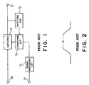
- the conventional signal control apparatus has a disadvantage in that it is difficult to change a strength of the apparatus output signal as will be discussed in detail with reference to the drawing.
- the conventional signal control apparatus is for controlling an apparatus input signal to produce an apparatus output signal and comprises a signal producing circuit 11, a detecting circuit 12, a comparing circuit 13, and an amplifier 14 which will presently be described.
- An output level control signal is supplied to the signal producing circuit 11 through a control signal input terminal 15. Responsive to the output level control signal, the signal producing circuit 11 produces a reference signal illustrated in Fig. 2.
- the detecting circuit 12 is for detecting the apparatus output signal to produce an output waveform signal representative of a waveform or envelope of the apparatus output signal.
- the comparing circuit 13 is connected to the signal producing and the detecting circuits 11 and 12 and is for comparing the output waveform signal with the reference signal to produce a difference signal representative of a difference between the output waveform signal and the reference signal.
- the apparatus input signal is supplied to the amplifier 14 through a transmission signal input terminal 16.
- the amplifier 14 is connected to the comparing circuit 13 and is for processing the apparatus input signal into the apparatus output signal under control of the difference signal.
- the apparatus output signal is sent out through a transmission signal output terminal 17.
- the waveform of the apparatus output signal is similar to that of the reference signal.
- the amplifier 14 is referred to as a signal processing arrangement.
- the conventional signal control apparatus produces the apparatus output signal which the waveform or envelope rendered simple. This is because the reference signal has a predetermined waveform which is simple as shown in Fig. 2.
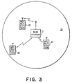
- the mobile telephone system comprises a base station 21 and a plurality of mobile stations 22, 23, and 24.
- the base station 21 has a predetermined service area 25.
- the mobile stations 22, 23, and 24 are movable in the predetermined service area 25.
- Communication can be carried out between the base station 21 and a selected mobile one of the mobile stations 22, 23, and 24 by the use of a radio signal.
- the radio signal is received as a received signal by the selected mobile station.
- the received signal has a received strength which varies dependent on a distance between the base station and the selected mobile station.
- the base station 21 comprises a receiver 26, a control circuit 27, and a transmitter 28.
- the receiver 26 Supplied with the radio signal through a receiving antenna 29R, the receiver 26 produces a demodulated signal and a reception input level signal.
- the control circuit 27 Supplied with the reception input level signal and the demodulated signal, the control circuit 27 produces an operation control and a level control signals. Responsive to the operation control and the level control signals, the transmitter 28 produces the radio signal.
- the radio signal is transmitted through a transmitting antenna 29T.
- the transmitter 28 comprises an original signal producing circuit (not shown) for producing the above-mentioned apparatus input signal in the manner known in the art.
- the signal control apparatus comprises similar parts designated by like reference numerals.
- the signal producing circuit 11 is included in the transmitter 28 and comprises first generating, second generating, operation control, and level control circuits 31, 32, 33, and 34.
- the first and the second generating circuits 31 and 32 are for generating a first and a second original signal which will later become clear.
- the operation control circuit 33 is supplied with the operation control signal from the control circuit 27 through an operation control terminal 35. Responsive to the operation control signal, the operation control circuit 33 produces a first and a second operation signal.
- the first and the second generating circuits 31 and 32 are connected to the operation control circuit 31 and are supplied with the first and the second operation signals. respectively.
- the level control circuit 34 is supplied with the level control signal from the control circuit 27 through a level control terminal 36. Responsive to the level control signal, the level control circuit 33 produces a first and a second level signal.
- the first and the second generating circuits 31 and 32 are connected to the level control circuit 34 and are supplied with the first and the second level signals, respectively.
- the first generating circuit 31 Supplied with the first operation signal, the first generating circuit 31 generates the first original signal under control of the first level signal. Responsive to the second operation control signal, the second generating circuit 32 generate the second original signal under control of the second level signal.
- each of the first and the second original signals will be referred to as an original waveform signal.
- the signal control circuit 11 further comprises comparison carrying out, selecting, and filtering circuits 37, 38, and 39.
- the comparison carrying out circuit 37 is connected to the first and the second generating circuits 31 and 32.
- the selecting circuit 38 is connected to the comparison carrying out circuit 37.
- the filtering circuit 39 is connected to the selecting circuit 38 and the comparing circuit 13.
- the first and the second original signals have various signal levels in the manner which will presently be illustrated.
- the first and the second original signals are supplied to the comparison carrying out circuit 37.
- the comparison carrying out circuit 37 is for carrying out comparison between the signal levels of the first and the second original signals to produce a result signal representative of a result of the comparison.
- the result signal is supplied to the selecting circuit 38 together with the first and the second original signals.
- the selecting circuit 38 is for selecting, as a selected signal, one of the first and the second original signals. In the example being illustrated, selection is carried out in the selecting circuit 38 so that the selected signal has a signal level which is a higher one of the signal levels of the first and the second original signals.
- a combination of the comparison carrying out and the selecting circuits 37 and 38 may be referred to as a wave synthesizing circuit.
- the selected signal has a selected waveform with leading and trailing edges and is supplied to the filtering circuit 39.
- the filtering circuit 39 is for smoothing the leading and the trailing edges of the selected waveform to process the selected signal into the above-mentioned reference signal.
- the filtering circuit 39 is referred to as an internal processing arrangement.
- a combination of the comparison carrying out, the selecting, and the filtering circuits 37, 38, and 39 is referred to as an internal producing arrangement.
- the operation control signal is depicted along top or first line labelled (a).
- the first operation signal is depicted along a second line labelled (b).
- the second operation signal is depicted along a third line labelled (c).
- An example of the first original signal is depicted along a fourth line labelled (d).
- An example of the second original signal is depicted along a fifth line labelled (e).
- An example of the selected signal is depicted along a sixth line labelled at (f).
- An example of the reference signal is depicted along a seventh or bottom line labelled at (g). In the manner exemplified along the bottom line, the leading and the trailing edges of the reference signal are rounded by the filtering circuit 39.
- the signal control apparatus comprises similar parts designated by like reference numerals.
- the signal producing circuit 11 further comprises first and second smoothing circuits 41 and 42.
- the first smoothing circuit 41 is connected to the first generating and the comparison carrying out circuits 31 and 37.
- the second smoothing circuit 42 is connected to the second generating and the comparison carrying out circuits 32 and 37.
- the first original signal has a first original waveform with leading and trailing edges and is supplied to the first smoothing circuit 41.
- the first smoothing circuit 41 is for smoothing each of the leading and the trailing edges of the first original waveform to process the first original signal into a first smoothed signal.
- the second original signal has a second original waveform with leading and trailing edges and is supplied to the second smoothing circuit 42.
- the second smoothing circuit 42 is for smoothing the leading and the trailing edges of the second original waveform to process the second original signal into a second smoothed signal.
- the first and the second smoothed signals have various signal levels in the manner which will shortly be illustrated.
- the first and the second smoothed signals are supplied to the comparison carrying out circuit 37.
- the comparison carrying out circuit 37 is for carrying out comparison between the signal levels of the first and the second smoothed signals to produce the above-mentioned result signal.
- the result signal is supplied to the selecting circuit 38 together with the first and the second smoothed signals.
- the selecting circuit 38 is for selecting, as the above-mentioned selected signal, one of the first and the second smoothed signals. In the example being illustrated, selection is carried out in the selected circuit 38 so that the selected signal has a signal level which is a higher one of the signal levels of the first and the second smoothed signals.
- the selected signal is supplied as the above-mentioned reference signal to the comparing circuit 13.
- the operation control signal is depicted along a top or first line labelled (a).
- the first operation signal is depicted along a second line labelled (b).
- the second operation signal is depicted along a third line labelled (c).
- An example of the first smoothed signal is depicted along a fourth line labelled (d).
- An example of the second smoothed signal is depicted along a fifth line labelled (e).
- An example of the reference signal is depicted along a sixth or bottom line labelled at (f).
- the leading and the trailing edges of each of the first and the second smoothed signals are rounded.
- the leading and the trailing edges of the reference signal are also rounded as will be understood from the bottom line.
- the signal control apparatus may comprise three or more generating circuits.
- the signal control apparatus is applicable to various kinds of time division multiple access communication network.
Claims (5)
- Signal-Regelgerät (28) zum Regeln eines Geräteeingangssignals, um ein Geräteausgangssignal zu erzeugen, mit einer Signalerzeugungseinrichtung (11) zum Erzeugen eines Referenzsignals, einer Detektiereinrichtung (12) zum Detektieren des Geräteausgangssignals, um ein Ausgangswellenformsignal zu erzeugen, das der Wellenform des Geräteausgangssignals entspricht, einer Vergleichseinrichtung (13) zum Vergleichen des Ausgangswellenformsignals mit dem Referenzsignal, um ein Differenzsignal zu erzeugen, das einer Differenz zwischen dem Ausgangswellenformsignal und dem Referenzsignal entspricht, und einer Signalverarbeitungseinrichtung (14) zum Verarbeiten des Geräteeingangssignals zu dem Geräteausgangssignal, gesteuert durch das Differenzsignal, wobei die Signalerzeugungseinrichtung (11) aufweist:
eine Signalerzeugungseinrichtung (31, 32) zum gleichzeitigen Erzeugen mehrerer Originalwellenformsignale, wobei die Originalwellenformsignale jeweils verschiedene Pegel haben; und
eine interne Erzeugungseinrichtung (37 bis 39, 41, 42), die mit der Erzeugungseinrichtung verbunden ist, zum Erzeugen des Referenzsignals unter Verwendung der Signalpegel der Originalwellenformsignale. - Signal-Regelgerät nach Anspruch 1, wobei die interne Erzeugungseinrichtung (37 bis 39) aufweist:
eine Vergleichsdurchführungseinrichtung (37), die mit der Signalerzeugungseinrichtung (31, 32) verbunden ist, zum Durchführen eines Vergleichs zwischen den Signalpegeln, um ein Ergebnissignal zu erzeugen, das einem Ergebnis des Vergleichs entspricht;
eine Wähleinrichtung (38), die mit der Vergleichsdurchführungseinrichtung (37) verbunden ist, zum Wählen, als ein gewähltes Signal, eines der Originalwellenformsignale mit Bezug auf das Ergebnissignal; und
eine interne Verarbeitungseinrichtung (39), die mit der Wähl- und der Vergleichseinrichtung (37, 38) verbunden ist, zum Verarbeiten des gewählten Signals zu dem Referenzsignal. - Signal-Regelgerät nach Anspruch 2, wobei das gewählte Signal eine gewählte Wellenform mit Vorder- und Hinterflanken aufweist, wobei die interne Verarbeitungseinrichtung (39) zum Glätten jeder der Vorder- und der Hinterflanken dient.
- Signal-Regelgerät nach Anspruch 2 oder 3, wobei jedes der Originalwellenformsignale eine Originalwellenform mit Vorder- und Hinterflanken aufweist, wobei die interne Erzeugungseinrichtung (37 bis 39) ferner eine Glättungseinrichtung (41, 42) aufweist, die mit der Vergleichsdurchführungseinrichtung (37) und der Signalerzeugungseinrichtung (31, 32) verbunden ist, zum Glätten jeder der Vorder- und der Hinterflanken.
- Signal-Regelgerät nach einem der Ansprüche 1 bis 4, wobei die Signalerzeugungseinrichtung (31, 32) aufweist:
eine erste Erzeugungseinrichtung (31), die mit der internen Erzeugungseinrichtung (37 bis 39, 41, 42) verbunden ist, zum Erzeugen eines ersten Originalsignals als ein bestimmtes der Originalwellenformsignale;
eine zweite Erzeugungseinrichtung (32), die mit der internen Verarbeitungseinrichtung (37 bis 39, 41, 42) verbunden ist, zum Erzeugen eines zweiten Originalsignals als ein spezifisches der Originalwellenformsignale;
eine Betriebssteuereinrichtung (33), die mit der ersten und der zweiten Erzeugungseinrichtung (31, 32) verbunden ist, zum Steuern der ersten und der zweiten Erzeugungseinrichtung, um zu bewirken, daß das bestimmte und das spezifische der Originalwellenformsignale eine vorbestimmte Beziehung haben; und
eine Pegelsteuereinrichtung (34), die mit der ersten und der zweiten Erzeugungseinrichtung (31, 32) verbunden ist, zum Steuern der ersten und der zweiten Erzeugungseinrichtung, so daß das bestimmte und das spezifische der Originalwellenformsignale einen bestimmten bzw. einen spezifischen Pegel aufweist.
Applications Claiming Priority (4)
| Application Number | Priority Date | Filing Date | Title |
|---|---|---|---|
| JP17718/90 | 1990-01-30 | ||
| JP20324/90 | 1990-01-30 | ||
| JP1771890A JP2646781B2 (ja) | 1990-01-30 | 1990-01-30 | 出力波形制御装置 |
| JP2032490A JP3147357B2 (ja) | 1990-01-30 | 1990-01-30 | 出力波形制御回路 |
Publications (2)
| Publication Number | Publication Date |
|---|---|
| EP0440186A1 EP0440186A1 (de) | 1991-08-07 |
| EP0440186B1 true EP0440186B1 (de) | 1995-12-20 |
Family
ID=26354282
Family Applications (1)
| Application Number | Title | Priority Date | Filing Date |
|---|---|---|---|
| EP91101198A Expired - Lifetime EP0440186B1 (de) | 1990-01-30 | 1991-01-30 | Signal-Regelgerät zum leichten Verändern eines Gerätausgangssignals |
Country Status (5)
| Country | Link |
|---|---|
| US (1) | US5152008A (de) |
| EP (1) | EP0440186B1 (de) |
| AU (1) | AU637185B2 (de) |
| CA (1) | CA2035203C (de) |
| DE (1) | DE69115512T2 (de) |
Families Citing this family (2)
| Publication number | Priority date | Publication date | Assignee | Title |
|---|---|---|---|---|
| US5697073A (en) * | 1994-08-26 | 1997-12-09 | Motorola, Inc. | Apparatus and method for shaping and power controlling a signal in a transmitter |
| US8061064B2 (en) | 2007-05-10 | 2011-11-22 | Esco Corporation | Wear assembly for excavating equipment |
Family Cites Families (8)
| Publication number | Priority date | Publication date | Assignee | Title |
|---|---|---|---|---|
| US4442407A (en) * | 1982-06-11 | 1984-04-10 | The United States Of America As Represented By The Secretary Of The Army | Two loop automatic level control for power amplifier |
| JPS5999851A (ja) * | 1982-11-29 | 1984-06-08 | Nec Corp | 信号制御回路 |
| JPH0683085B2 (ja) * | 1986-03-26 | 1994-10-19 | ソニー株式会社 | 送信機 |
| GB2220808A (en) * | 1988-07-15 | 1990-01-17 | Philips Electronic Associated | Power amplifying arrangement |
| US5003619A (en) * | 1989-01-31 | 1991-03-26 | Motorola, Inc. | Method and apparatus for adjusting the power of a transmitter |
| JPH02246531A (ja) * | 1989-03-20 | 1990-10-02 | Fujitsu Ltd | 送信電力可変形送信機の送信断検出回路 |
| JP2769478B2 (ja) * | 1989-04-10 | 1998-06-25 | 三菱電機株式会社 | 無線機 |
| US5056109A (en) * | 1989-11-07 | 1991-10-08 | Qualcomm, Inc. | Method and apparatus for controlling transmission power in a cdma cellular mobile telephone system |
-
1991
- 1991-01-29 CA CA002035203A patent/CA2035203C/en not_active Expired - Lifetime
- 1991-01-30 US US07/648,689 patent/US5152008A/en not_active Expired - Lifetime
- 1991-01-30 DE DE69115512T patent/DE69115512T2/de not_active Expired - Lifetime
- 1991-01-30 AU AU70112/91A patent/AU637185B2/en not_active Expired
- 1991-01-30 EP EP91101198A patent/EP0440186B1/de not_active Expired - Lifetime
Also Published As
| Publication number | Publication date |
|---|---|
| EP0440186A1 (de) | 1991-08-07 |
| AU7011291A (en) | 1991-08-01 |
| DE69115512D1 (de) | 1996-02-01 |
| AU637185B2 (en) | 1993-05-20 |
| DE69115512T2 (de) | 1996-05-15 |
| CA2035203C (en) | 1995-02-14 |
| US5152008A (en) | 1992-09-29 |
Similar Documents
| Publication | Publication Date | Title |
|---|---|---|
| EP0582323B1 (de) | Verfahren und Vorrichtung zur Diversityübertragung und Empfang | |
| EP0352787B1 (de) | Kommunikationssystem mit hoher Bitrate zur Überwindung der Mehrwegsausbreitung | |
| HK1019022A1 (en) | Adaptive sectorization in a spread spectrum communication system | |
| CA1246148A (en) | Radio system wherein transmission power is varied according to transmission quality | |
| US5548834A (en) | Radio telecommunication system with a multi-sensor receiver station and a plurality of emitter stations transmitting data packets | |
| AU1769097A (en) | Method and apparatus for directional radio communication | |
| CN1145706A (zh) | 蜂窝无线电系统、中继器和基站 | |
| AU1724797A (en) | Method and apparatus for directional radio communication | |
| EP0763307A2 (de) | Diversitykombinator für antennen | |
| EP0468688A2 (de) | Verfahren und Vorrichtung zur drahtlosen Kommunikation zwischen entfernten Lagen | |
| EP0964596B1 (de) | Verfahren zur Kanalzuweisung mit Berücksichtigung der Ausbreitungsverluste | |
| US4232392A (en) | Radio transmission systems | |
| EP0440186B1 (de) | Signal-Regelgerät zum leichten Verändern eines Gerätausgangssignals | |
| CN100391110C (zh) | 在tdd系统中降低干扰的方法 | |
| CA2215788A1 (en) | Fixed station of mobile radio system | |
| EP0762670A2 (de) | TDMA Kommunikationsverfahren für Basisstation die für verschiedene Zonen verschiedene Frequenzen anwendet und Empfänger dafür | |
| Akaiwa | Antenna selection diversity for framed digital signal transmission in mobile radio channel | |
| US7095711B1 (en) | Communication method and apparatus for a radio local area network system using macrodiversity | |
| US6701157B2 (en) | Transmitter circuit architecture and method for reducing in-band noise in point to multipoint communication systems | |
| US4683566A (en) | Digital radio communication system | |
| JPH0761177B2 (ja) | 広域移動体通信方式 | |
| JPS5773539A (en) | Mobile radio communication system | |
| JPH0730880A (ja) | Catvコンバータ | |
| JPH09270715A (ja) | 送信回路とその初期設定方法 | |
| JPH0336357B2 (de) |
Legal Events
| Date | Code | Title | Description |
|---|---|---|---|
| PUAI | Public reference made under article 153(3) epc to a published international application that has entered the european phase |
Free format text: ORIGINAL CODE: 0009012 |
|
| 17P | Request for examination filed |
Effective date: 19910220 |
|
| AK | Designated contracting states |
Kind code of ref document: A1 Designated state(s): DE FR GB NL SE |
|
| 17Q | First examination report despatched |
Effective date: 19930916 |
|
| GRAA | (expected) grant |
Free format text: ORIGINAL CODE: 0009210 |
|
| AK | Designated contracting states |
Kind code of ref document: B1 Designated state(s): DE FR GB NL SE |
|
| REF | Corresponds to: |
Ref document number: 69115512 Country of ref document: DE Date of ref document: 19960201 |
|
| ET | Fr: translation filed | ||
| PLBE | No opposition filed within time limit |
Free format text: ORIGINAL CODE: 0009261 |
|
| STAA | Information on the status of an ep patent application or granted ep patent |
Free format text: STATUS: NO OPPOSITION FILED WITHIN TIME LIMIT |
|
| 26N | No opposition filed | ||
| REG | Reference to a national code |
Ref country code: GB Ref legal event code: IF02 |
|
| PGFP | Annual fee paid to national office [announced via postgrant information from national office to epo] |
Ref country code: SE Payment date: 20091218 Year of fee payment: 20 |
|
| PGFP | Annual fee paid to national office [announced via postgrant information from national office to epo] |
Ref country code: FR Payment date: 20100208 Year of fee payment: 20 |
|
| PGFP | Annual fee paid to national office [announced via postgrant information from national office to epo] |
Ref country code: GB Payment date: 20100202 Year of fee payment: 20 Ref country code: DE Payment date: 20100211 Year of fee payment: 20 |
|
| REG | Reference to a national code |
Ref country code: NL Ref legal event code: V4 Effective date: 20110130 |
|
| REG | Reference to a national code |
Ref country code: GB Ref legal event code: PE20 Expiry date: 20110129 |
|
| PG25 | Lapsed in a contracting state [announced via postgrant information from national office to epo] |
Ref country code: NL Free format text: LAPSE BECAUSE OF EXPIRATION OF PROTECTION Effective date: 20110130 |
|
| PG25 | Lapsed in a contracting state [announced via postgrant information from national office to epo] |
Ref country code: GB Free format text: LAPSE BECAUSE OF EXPIRATION OF PROTECTION Effective date: 20110129 |
|
| PG25 | Lapsed in a contracting state [announced via postgrant information from national office to epo] |
Ref country code: DE Free format text: LAPSE BECAUSE OF EXPIRATION OF PROTECTION Effective date: 20110130 |
|
| PGFP | Annual fee paid to national office [announced via postgrant information from national office to epo] |
Ref country code: NL Payment date: 20100131 Year of fee payment: 20 |